Thank you, much appreciated.
(This is cutnpasted from my Notes app because I wanted to get it all in order before I asked)
I have small robotic device and I would really like to ask you all for some guidance to solve a problem I have discovered… but…I will have to be fairly vague about it and exactly what the device does, certainly won’t be able to provide any photos etc, because it is not yet released (I hope you understand).
I have no access to firmware. No intention of making any modifications to the mechanics or PCB etch. I can use a soldering iron and read/follow clear guidance but what I am hoping to achieve needs to be completely confined to one specific area and be non-invasive and 100% reversible (and certainly, with your help, cause no damage to the device nor leave any trace of my tinkering) … It may, after all, need to be returned to the project at some point. But, if (with your help) we find a solution to the issue I have discovered, then I’ll be making sure that they know .
And, I’ll be up front, everything I have read so far has been at the suggestion of various Ai platforms and the more I read, the further down the rabbit hole I’m getting and it’s time for some human intervention/interaction.
A brief description of the device.
It is small, has two wheels driven by N20 brushed DC motors. The PCB components are, from what I have discovered, not the absolute state of the art but still current and are more than adequate for the task and actually capable of much more than they are being asked to do. A decent SOC for PWM control, h-bridges etc… The little thing does it’s job quite well, certainly accurately enough for its intended purpose.
But it has a few annoyances.
And the frustrating thing is they are, in some ways, linked.
1…It currently operates (according to my rudimentary audio recordings and analysis of said recordings by several Android apps and also online platforms) at a pwm frequency of 1khz (with harmonics at approximately 2khz and 5-6ish). It whines like a giant mosquito trapped in a jar and is thoroughly unpleasant and distracting (certainly for me and I believe it will be for everyone else, it is definitely off-putting considering it’s intended use). Everything I have read suggests that changing the PWM is relatively simple, just a few changes to the code that really doesn’t impact on anything else. Importantly, a change of the PWM up to 12khz minimum (16khz > even better) would result in what I would consider to be a “net-positive”. Any increase in heat generation on the chips or motors will be negligible, active times are so short and idle times plenty long enough for the heat to dissipate. Improved user enjoyment (no whine) would be a huge part of that “net-positive” but more efficient motor response and smoother travel would make it aesthetically more pleasing to interact with. But I can’t do anything about that, the firmware is locked down and the devs seem to consider that the current levels of noise are acceptable… They’re in for a shock, I’m confident of that.
2…However… The actual run-times are a tremendous disappointment 
 .
It is powered by a tiny 701530 300mah 3.7v Lipo. My understanding is that it was originally specced out and could achieve 6-8 full “cycles” (plenty) before it would automatically return to its charging dock (powered by 5v usbc). Component failures in the drivetrain, after continuous testing, forced a change of gearbox/ratios. I strongly believe this change is the root cause and has had a knock-on affect on run-times and it now, repeatedly and 100% consistently, completes only 2 full cycles and very early into the third, voltage sag triggers the command to return to the dock. It’s so, so frustrating. And again, when it’s out in the market, owners will absolutely not be satisfied with that drop in expected performance. Not only that, if the device needs to recharge three times more often, that little battery is going to degrade pretty rapidly.
It’s a shame that this is how it’s turned out because the package as a whole is well made, improves on the similar devices (currently available) in several important aspects. But this one particular issue will be a killer, I couldn’t be more sure of that. Nothing can be changed for this upcoming market release, it’s pretty much boxed and ready to go. When the complaints flood in, they will then realise that they need to design a version 2 but even that will need to maintain the overall dimensions of the existing device for it to be compatible with the rest of the package otherwise the whole thing entirely would need to be changed. So my solution (if it works) could be delivered as an aftermarket upgrade without any physical changes required.
And this is what has brought me here, seeking your thoughts and advice.
Because (I thiiiiiink) that there is a fairly straightforward solution that I would like to test but I need real advice from real people before I take the plunge (and I absolutely don’t want to break anything).
There are some unfortunate physical limitations that can’t be changed. I say “can’t” but, if it was actually mine to do as I please, I would have Dremeled it’s guts out. But I can’t.
Meaning the battery chamber is the problem because it was designed for this particular battery with its teeny tiny JST-SH 1.0MM plug. It was always intended to be user serviceable regarding the battery, so it’s plug/socket are accessible. But the space is, for all intent and purpose, restricted to 10mmx20mmx35mm. Even that is misleading though, because the design of the robot has a rounded nose and this is where the battery is located, so the battery maximum length is directly related to the thickness..thicker would need to be shorter and up to 8mm could probably use the full length etc, because of how the battery sits in the chamber. And normal charging expansion and manufacturing tolerances need to be accounted for. My best guesstimate is those dimensions all need to be reduced by 10% to be safe and make it easier for users to install. Fortunately, it isn’t an actual 10x20x35 sealed box, they’re just the boundaries in space and it’s reasonably “open” air around it, there’s just screw-bosses and reinforcement ribs in the lid etc that create these size restrictions. The one absolute is the 20mm(minus 10%) because the lid must go back on for the public release. Another fortunate is that it’s away from the motors etc so their heat generation will have minimal affect. Unfortunately, the bottom edge of the battery sits squarely over about 50% of the main controller chip (separated by a thin layer of insulating foam). As I mentioned earlier, the chip is working well below it’s capabilities and I have not noticed any heat but squashing a thicker battery down on it isn’t my idea of prudence…Dear Prudence..Won’t you come out to play? (that’s given my age away!).
I have already purchased a 702030 350mAh battery and made an adapter cable to go from JST-PH 2.0mm down to the SH and every test now produces exactly 1 more full cycle and then it automatically docks. The 20mm of the battery actually turned out to be 19.23 (the folds of the foil compressed slightly) after I gently coaxed the lid back on and screwed it shut. But that was before I understood that these packs can swell by 5-10% normally during charging.
One more cycle is better but nowhere near enough.
The plethora of Lipo battery shapes and sizes is bewildering and annoyingly difficult to choose from, mainly because it’s obvious that far too many sellers have them printed with mAh capacities that just aren’t possible given the energy density characteristics of these packs. So limiting myself to what I hope are “reliable” brands such as Eemb/Liter/YDL (recommendations for other brands are very, very welcome) has meant that the sizes I would have liked to test (ie 901730, 801835) just aren’t available from stock. And there’s no point wasting money on spuriously claimed capacities.. I would rather (and will) spend the money on a decent Lipo charger that can accurately gauge the charge/discharge rates and confirm the mAh. There are several standard cells that are in the range of 450>600mAh that would physically fit but just aren’t available from stock anywhere. The ones that I could purchase are all 20mm wide and that’s not going to be viable (as a permanent solution) now I know what I know. A caveat to this… If I do get to keep it, I would be happy to operate it with the lid off (it makes no difference to its operation) so 20mm could work.
I’ve had lots of back and forth with manufacturers in China but, unless I pay silly money for expedited shipping, the wait is at least a month.
Days and days of reading and asking Ai questions has lead me to believe that there is a solution… But these Ai advisors are fickle! And time and time again they will spend ages explaining what can be done and what I need etc… But then when I return and ask the same questions with specific reference to components they told me to source, they will contradict everything previously suggested and tell me it can’t be done.
This, in a nutshell, is what has been suggested.
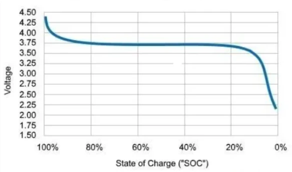
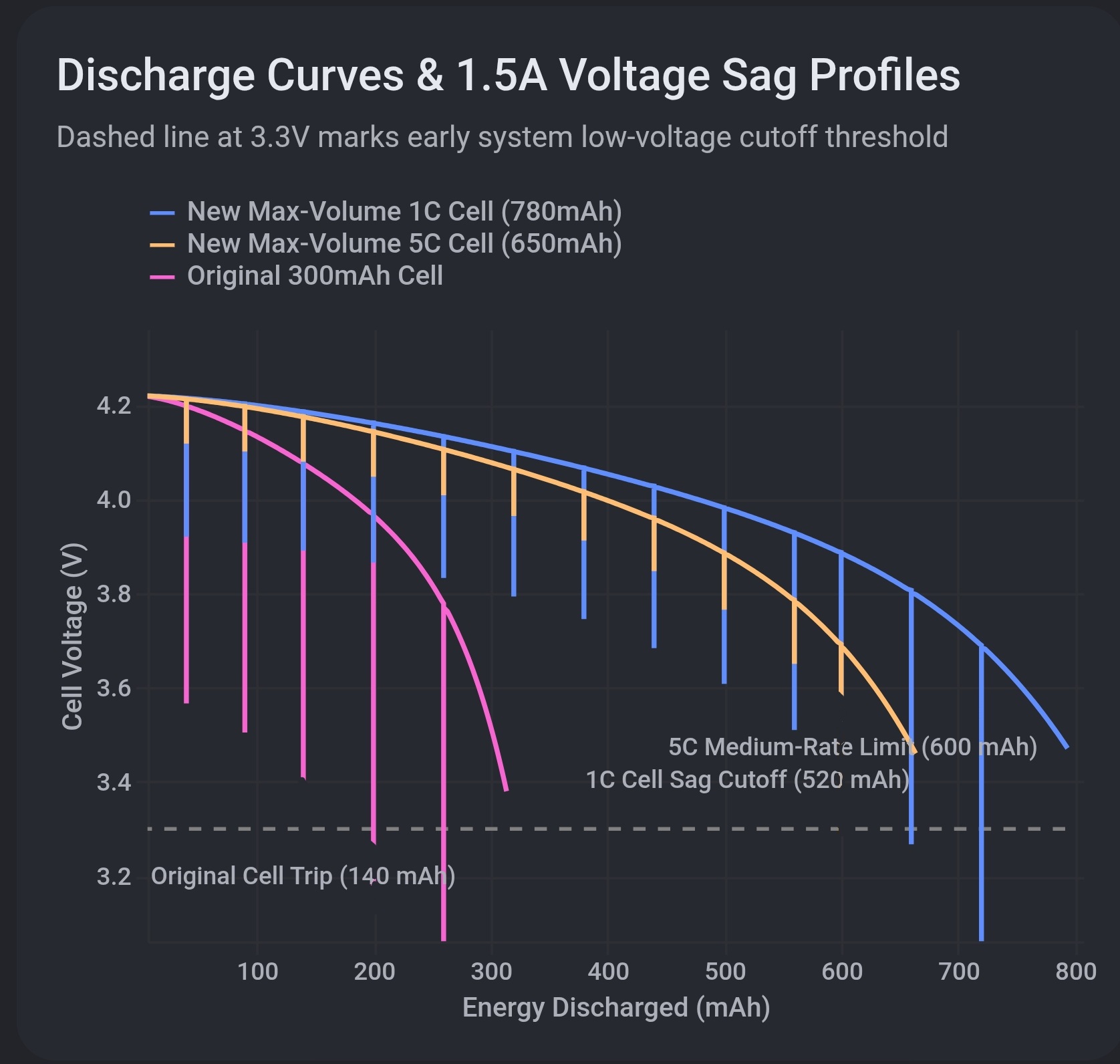
Voltage sag is the trigger (I concur).
300mAh is never going to be enough (I concur).
The 350mAh giving me an extra cycle indicates that a cycle consumes in the region of 50mAh (sounds reasonable?).
Therefore, 600mAh would be a reasonable capacity to achieve the number of cycles it was intended for, with a tiny bit to spare (again, sounds reasonable?).
But those capacities aren’t available in a physical form, off the shelf, for me to test.
Ai then continued.
Because voltage sag was the trigger, swapping to a high-c Lipo would effectively eliminate this (sounds good?).
Because the battery could deliver the power without voltage sag triggering the automatic recharge so early, I would actually get more cycles from a high-c 300mAh before needing to recharge (sounds good?).
Therefore (and because I could order some right now for delivery next day) there are 752035 400mAh high-c cells I could try that may get me close to the 6-8 expected cycles. Just for brief testing (and my earlier caveat) I am happy to leave the lid off but that could not be a permanent solution for the public release (sounds good so far?).
Then they throw a spanner in the works.
High-c Lipo’s generally don’t have pcm/bcm (defeats the purpose?).
I want a solution that does include some safety measures (that’s an absolute necessity for the retail device).
So they tell me I could use the pcm from the existing battery and, because it was already compatible with the charging system and the power requirements of the robot, this would be an “excellent” solution (I’m feeling better).
But I don’t want to butcher the only “correct” battery I have. I explained this and asked if the pcm from the second battery would be suitable? Now they start telling me that using the pcm from a standard battery would be (depending on the time of day I have asked)
dangerous
pointless as it would bottleneck the current
a great idea
not going to work and will almost certainly cause the robot to stop in its tracks if it tried to draw too much current
back to excellent.
And now, finally, exhaustingly, after feeding it every bit of specific information I have about the components I have identified, they seem to have settled on this next solution. I have fed them with the same information several times and the answer is the same.
Source high-c cells that DO have a protection circuit (found some).
Source some pigtails with JST-SH 1.0MM plugs (already have some).
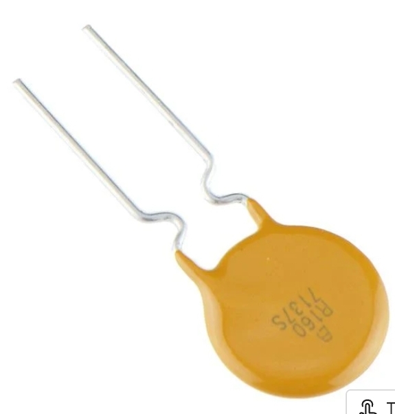
Solder into the positive supply a 0.5amp resettable ptc fuse (to prevent any high current spikes reaching the PCB or even the pins/28awg wire in the JST-SH plug (sounds reasonable?)… (but if it is tripped the robot is then innactive until it resets surely?).
Plug in and test.
So, real people who have stuck around to the end of this saga.
What do you think?
Will it work but be risky?
Will it work and be perfectly safe?
Is there a better solution?
Or is this just a doomed quest?
The resettable fuse sounds plausible but I am thinking that I need to somehow find just the right size that will be a safe balance of protection but not keep tripping every time the device hits an obstacle and (momentarily until it’s control code recognises and reverses) it tries to drive and the motors draw more current and stall.
If we can solve this step, I think that someone here will also have the knowledge to attack the firmware somehow (intercept the firmware download?) and start playing with the PWM… But that’s for another day.