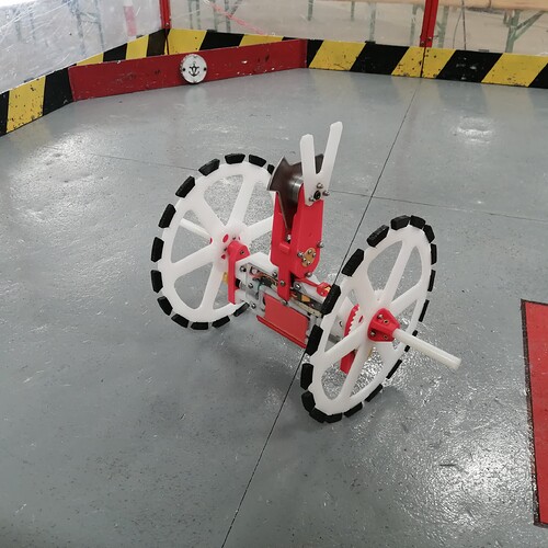
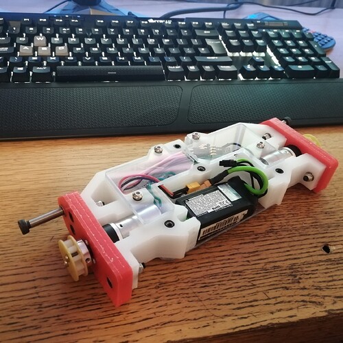
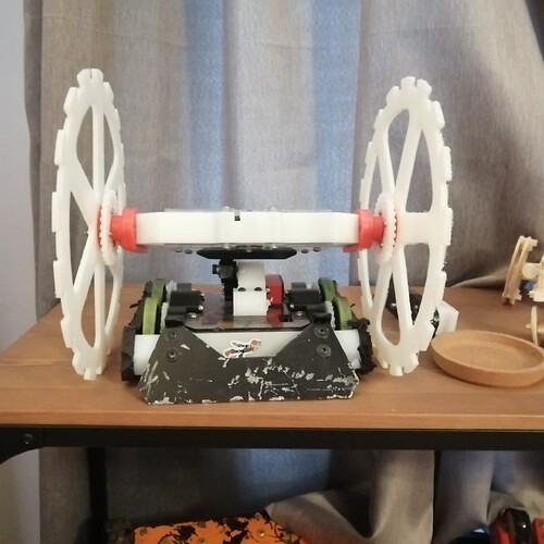
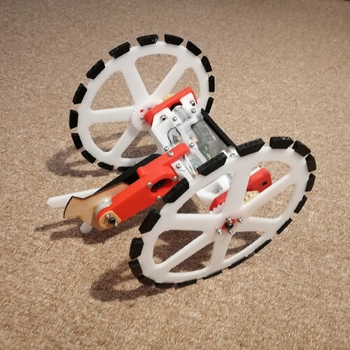
Wheely big Lad! What is it? Why is it? How do I make it hit stuff? Which way up is it?
Thought I’d do a sortof build log/robot report on Wheely Big Lad as a bit of recording and resource for anyone following in the Big Wheel Meta (The superior one of course).
A Bit Of Background
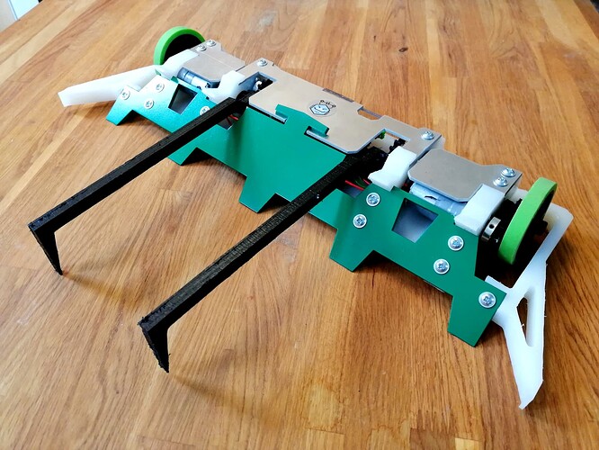
For a long time I didn’t like Beetles, not the fault of beetles. It was all the fault of WIDEBOI who never really wanted to work through numerous iterations. WIDEBOI wa a rathe rawhide 2wd pusher with ‘wagglesticks’ for weapons that kept resisting all attempts to make it work well. Following that I wanted to ‘reset’ in the weight class and built Boring Bot. Boring bot existed in quite a few iterations but normally a pusher with again wagglesticks but this time in a compact typically billet body. Boring Bot was more a testbed of different ways of making robots, what works/what didn’t. Even down to simply different versions bolting together different ways just to explore the class a bit before I wanted to build something more fun. After a while of playing around with things I had a set of build methods I was happy with and a bit of success with Boring Bot and was ready to move on to something more fun. I also knew I wanted my next robot to have some KO potential but being one of my robots I didn’t want to just build something generic, much rather enjoy more out there robots.
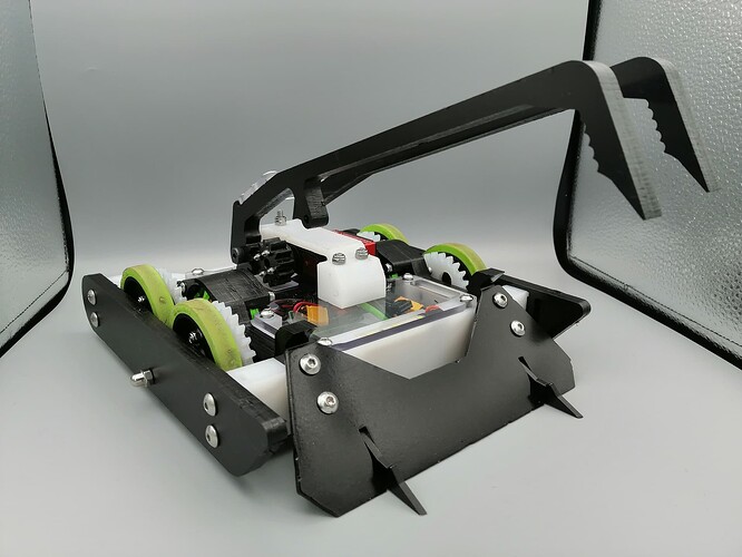
I also didn’t like playing the ground game of people having super long forks or getting beaten up by lots of drums I seemed to attract. Rory had been building ‘Trash Panda’ an agricultural UK version of the American Beetle ‘Starchild’ by Brandon Zalinsky. However Rory stopped pursuing the robot and wanting to finally move onto something more exciting I asked if I could (With Brandon’s permission) pick up the torch.
Initial Design
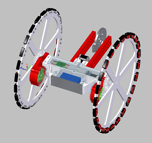
The first step was roughing out some CAD for the robot. Now having an existing robot it was based on meant that the starting point was a bit further along than normal. However this still went… Poorly. I designed a few versions but I frankly hated them I mean look at this:
Sure that’s some big nicely counterweighting brushless pancakes but… Where’s the style? The initial plan was big 3508’s for a violent thwack. I shelved the design for a year or so before returning to it.
The Starchild design generally has a fairly light spinner but is making up for it by attacking the less armoured lids of robots and by getting a very high engagement speed by swinging it into the opponent, so power in the drive and the centre of mass very close to the drive axle is very important. The other thing to consider is how long the arm is, longer gives you more speed when it swings for engagement but makes it harder to balance the robot (Like a spinner the whole robots needs to be roughly balanced for this, though there is a good amount of leeway). Seemed the roughly sensible thing was the weapon axle nearish along the arc of the diameter of the wheels.
Once I had an initial design I spoke with Brandon who was very helpful and happy to give some pointers and let me know if I’m even in the ballpark.
Maintainability was also a huge consideration. I wanted to be able to access and swap every part with minimal fuss and without entire robot dismantling. Everything should at most only require 1 other thing to be unbolted to get to it. For example to take an entire side bulkhead off you only need to remove a wheel. The weapon arm can be swapped entirely from the outside of the robot. The wheels I can premake a bunch and just swap them with a single bolt. The disc can be removed with 1 bolt, and the disc changed with 4. The belt or weapon motor does not need to be removed to work on the weapon either.
Electronics
To keep it simple I went with a BBB Dual Brushed Beetle ESC and on advice scaled the drive back to the 22mm motors for more precise control over the 3508 brushless motors, the brushless while more powerful tends to have a higher ‘minimum’ speed it’ll move at which with the minimal reduction I could do was not enough for any precise work. And to start with was much easier to implement and I was still wary of over complicating things.
An Afro 30A with tweaked SimonK firmware drives the spinner (Yes my parts collection is that ancient but I refuse to let go of my SimonK). An EMax 2204 powers the weapon, how it doesn’t cook itself I’m not sure but Tweedy had shown successful use in a heavier weapon setup and I desperately needed to save weight and space over the originally chosen 28-30 Propdrive (Which I chose because I already have a bunch of them). A Flysky 4ch receiver powered off of the Dual ESC’s BEC for control. An XT30 with one of my lazily done ‘fuse links’ (A miniblade fuse fits almost perfectly in the pins of an XT30) for a removable link. Overlander 3S 850mAh provides power; I decided to play it safe voltage wise initially. Remember this comes off the back of WIDEBOI that’s unreliability made me dislike beetles, I was more concerned about it working than being the most spectacular thing ever. The wiring is connectorised inside with more XT30’s to allow for a quick swap in the pits without touching the soldering iron if needed. XT30’s can be a little big but haven’t giving me any issues and are nice and solid I find.
Chassis
I’d been playing with this Semi-Billet HDPE chassis for a while now with Boring Bot. The core of the robot is a HDPE Billet with the drive self-contained to 2 bolt-on bulkheads on each side. This makes for an easy build and a quick maintainable robot. The other plus is that I own my own CNC router, and this method allows me to get the machine to do as much of the precision work as possible, often the best build solution is what is easiest for your tooling not the fanciest. For me this method is easy and cheap. A bit of 3mm Hardox metal armour at the front acts as a counterweight to help pull the robot’s centre of mass away from the weapon end and back to the axle, again needed for the robot to thwack easier. It also provides some key protection to the battery, who gets pride of place up front again to shift the weight, however the front of this robot is vulnerable to tall verts.
Like most my beetles it centres around CHONK use of HDPE. I like it’s flexibility and ability to absorb impact, and it is fairly low priced. PE 500 is ideal to me but 300 is fine for large chunks. I like to use choice bits of metal where I expect hits to come in and then rely on the flex of the chassis to absorb the energy the armour plate takes and hopefully the whole thing comes out unscathed. The fasteners are standardised to almost entirely M4 on the main body as it’s a size that feels robust enough without requiring a lot of weight or space.
Polycarb armour on the top and bottom protects the internals. Now I will readily admit polycarb is not the best choice here, but I am a sucker for the aesthetic. These are held on by threaded standoffs pressed into the billet chassis. The standoffs don’t have anything to stop them rotating (I’ll probably use hex ones in future) but no trouble anyway. The fact a bolt goes into each end stops them turning in annoying ways.
Wheels
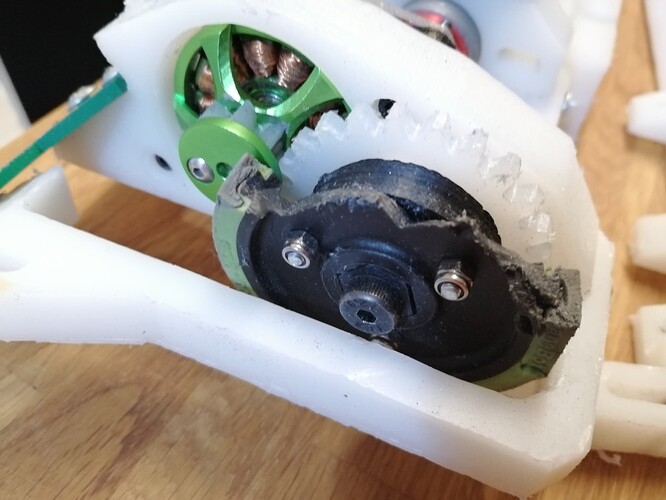
The wheels were one of the trickier sides of this, they represent a good portion of the weight being so large but are also the main armour of the robot. Part of the benefit of big wheels is the body is less likely to take a hit, but the wheels definitely will. In the end I had to settle on 4mm HDPE, I really wanted to go for 6 initially but didn’t have the weight spare. I even had to shave down the diameter to 26cm to cut a little more (This did cause a problem later on). Tyres were another tricky thing, I wanted something that was a ton of different sections so any damage was localised to easily replaceable bits and I wouldn’t lose all the grip at once. I’d seen Stratus using long thin sections of around 2-4 per wheel (Sorry don’t exactly remember) and it had a bad habit of losing huge sections of grip in one go. My first attempt was far over engineered, each foot a bit of foam held on by a 3d printed clamp and 2 bolts, which doesn’t sound too bad until you consider how many it needed. Eventually I settled on socks after playing with TPU, easily printed and could just stretch over a T shape on the wheel. No fasteners and I can just keep a bag of them to replace lost ones. There are also the sticks on the wheels that just help discourage it from balancing on its side in a fight, these are just held on with a printed adapter which importantly contributes nothing to the wheel structure. The axle just goes into a threaded insert in the bulkhead, I’ve been doing this since day 1 of my beetles and it stands up far better than it has any right to, I have yet to lose an axle even with direct hits that have broken the wheel on it in half. WBL needs an additional reduction stage of routed Nylon gears to bring the speed back down to sensible levels and also to ‘isolate’ the motor from having wheels directly on them. Though the speed is still relatively high for a beetle, I just couldn’t fit in anymore reduction. The smaller of the gears gets 2 guide plates either side to stop the gears unmeshing if things are getting knocked about. I often even do this kind of thing on beetles even without reduction (Just a 1:1) to protect the motors for a very minimal weight penalty.
WIDEBOI using the same wheel mounting after a hefty hit to the wheel, didn’t stop!
I’m happy incorporating printed parts in my drive setups but a crucial thing for me is I like all power to be transmitted through bolts, through the faces of the components. I do not like transmitting torque through the shaft, not only does this rule out dead shafts which are nice and easy but the closer they are to the shaft (like a grub screw) the more torque it is fighting. Also even if the printed parts fail the bolts will roughly hold it together and the wheel is unlikely to fully break free without shearing the bolts.
Spinner
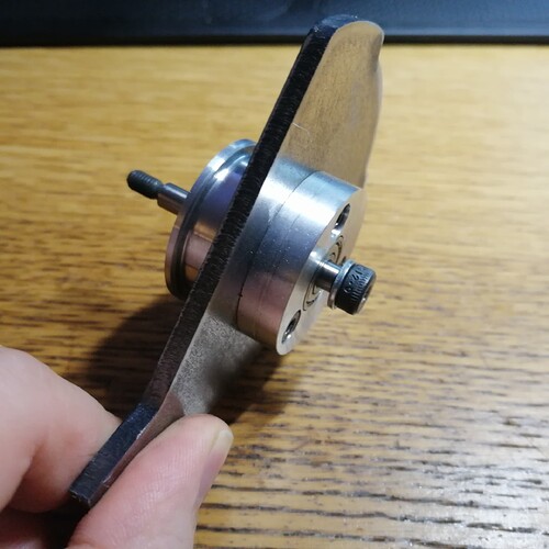
The spinner was honestly a bit thrown together, wasn’t really 100% sure on what I was doing and it was getting pretty late in time for the event it was signed up for. I threw it together with a dead shaft axle (A ground shoulder bolt), 2 ali pulley sections that had a bearing each and sandwiched the disc, a T5 6mm wide belt and the Emax 2204. The pulleys have a reduction to take me to about ~240mph and a toothed pulley motor side with smooth on the weapon to allow a bit of a clutch effect on hits. The motor is single supported on a sliding mount to adjust the belt tension, I honestly expected it to die like this. Some small thin bits of GR4 are sprinkled in places to reinforce the holes of the HDPE from deforming, you can see these behind the motor and either side of the disc. I had horrible visions of on hits the belt pulling the motor can and the shaft bending without double support but it just never happened. Birthday lad Felix bailed me out of the time hole I dug myself when I asked him if he could maybe help me out with making the pulleys in the evening. He said he’d “take a look” and I had a picture of them the next morning. What a top lad!
A 3mm Hardox disc of only around 140g is the spinner itself, around 120mm diameter. A relatively small spinner in beetles, but as mentioned it relies on engagement speed and hitting unarmoured areas to do work. A very simple symmetrical counter weight design. 2 teeth as I wasn’t sure if I may want to make the disc spin either way in future and worst case each disc has 2 teeth to damage before they are done. I went for the ‘paintless’ look on the discs I like to call “Weight is getting a bit tight” silver.
2 HDPE ‘ground stops’ are used to stop the disc hitting the floor, these took a while to refine as they will by nature interfere with hits and needed carefully sorting to make sure it wasn’t too bad. They are also prone to taking damage, which is unfortunate as due to a limit of space they are the least easily swapped part. Not too bad as the robot is very maintainable overall but these lost.
The Build
This was honestly the very simple part, I designed it to go together easily once the router had done it’s work. Almost like bolting together IKEA. Largely done in a day and then just tweaking and swapping parts as I go after. This is fairly typical, I tend to focus heavily on the CAD side (Being my day job and all) to simplify the real world part of the robot. There is some work I need to do like drilling holes in the side of the billet but even then the CNC helps. I get the router to notch the chassis where the holes will be and then I just need to mark the height of them and pillar drill them. Sorry not too much to say here, I press buttons and get parts then bolt together. A few stand-in parts were used while I waited for the real ones to appear.
The main work is done on a Workbee router programmed up in glorious CAMBAM with it’s slick modern interface… If this was still the early 2000’s.
Testing
Testing was limited as I don’t have a great test setup right now, just a garage and some spare polycarb sheets I can hide behind. But it drove very nicely. Aiming thwacks is not easy however and I still don’t know how Brandon does it so well. No real surprises from testing, it was all fairly happy, main point was fine tuning how high the ground stops hold the disc off the floor. Closer it is the less the stops interfere with hits but too close and you risk hitting the floor on missed thwacks or trying to drive.
But I now had a robot and it had an event. I was pretty excited to try it and it had been fairly well under wraps from the community. Even the picture of it as a heat seed was cropped to hell and back, flipped and rotated upside down to try and hide what it was. Paraphrasing my own words “I’ll be damned if it gets attachments against it before it’s even fought”.
