All of the components minus battery will be from the BBB store, and I’ll be running the 25mm wheels, N10s most likely, the red ESCs that solder directly to the back of the gearmotors, and the default spinner brushless motor on the store as well. motors will be friction fit (with some electrical tape). Haven’t tested this on anything that’s been in a fight, but seems to hold up well enough when driving. Case will be 3d printed in something lightweight, but strength probably won’t matter too much as the spinner is basically armour anyway
I also want to test its balance when I put it together, and I have a test box which I made from some 16mm MDF with a 6mm polycarb lid (screwed in place)
Could you guys give me any advice for the robot?
Thanks a lot,
Ollie.
P.S, so that the blade actually hits things, I’m going to add a small tab on the rear side, so that the body angles downwards.
Looks like Ernie had a baby! My tip is to be careful with switch placement. We had a similarly big weapon on another robot, where the switch was right in the weapon’s path. Think hard about where to put it, since if the motor activates when it’s turned on, you’ll be in for a time. Overall the choice of components looks great (I presume there’s top armour). Not bad for the first time!
Thanks for this! About the switch, I’m probably going to use a battery plug, just so that I can scrap the switch and save a gram or two - actually having said that, this may begin to become a pain with top armour - I’ll think about it. I’m going to go test my electronics so that I don’t lose my fingers when testing lol. I’m using a flysky i6 or something which needs the throttle to be all the way down to start which is pretty phenomenal for my digits. Top armour will probably just be a layer of acetate or something, doesn’t need to be strong, just hold the components in and AWAY from the spinner.
Anyways thanks a lot!
You’ve reminded me that I need to put some holes in for the motor wires.
Don’t underestimate the forces involved here! A sheet of acetate will certainly flex enough on a big hit to get your internals right in the path of the weapon - would recommend a decent printed lid at least. You’ll also need a locking bar for your weapon that stops it rotating so a sturdy lid helps here. Finally, relating to forces, make sure your chassis is printed well enough that the motor doesn’t just rip itself out of the base on a big hit! Ant spinners worst enemies are so often themselves.
Like Craig said, keeping it rigid is actually quite important. Previously having ran an overhead 150g, I was using CF with a large 48g bar and was still able to flex into my own chassis.
I’d also check to make sure your battery can supply the motor with the current it demands. Again, was having those issues on my overhead. So just something to consider, it might need a higher C rating to keep up with the motors demands.
Would it be possible to use a clamp as a locking bar? I kind of thought about it when designing, and was thinking “yeah that should be fine”. For the chassis, I’m probably going to print it straight from PLA because cheap and easy, though I’ve heard good things in the way of TPU. Having said that, TPU would cause the mount to flex after an impact, potentially meaning the weapon could destroy all of the internals instantly…
In terms of Materials - do you think regular PLA would be fine? I’m a tad worried about the flex and the cracking, but I’d rather not go and go print something in carbon fibre for this - the weapon is basically armour anyway.
You should not use anything that could slip off - like a clamp
Put a hole through the chassis that you can drop a pin that will prevent the bar from doing a full rotation.
If you’re looking for something rigid, I’d look at Overture Super PLA+, really impact resistant & just as easy to print as PLA.
Seconding Craig on pin for a locking bar, but I’d take it one step further and make it a 2 pronged fork that you can put in 2 holes. Some people get weird about how much rotation the bar should & shouldn’t have.
Here’s a quick update for any that are at all interested:
I haven’t done much over the past few weeks just because of school exams, but have kept the project ticking, if you will.
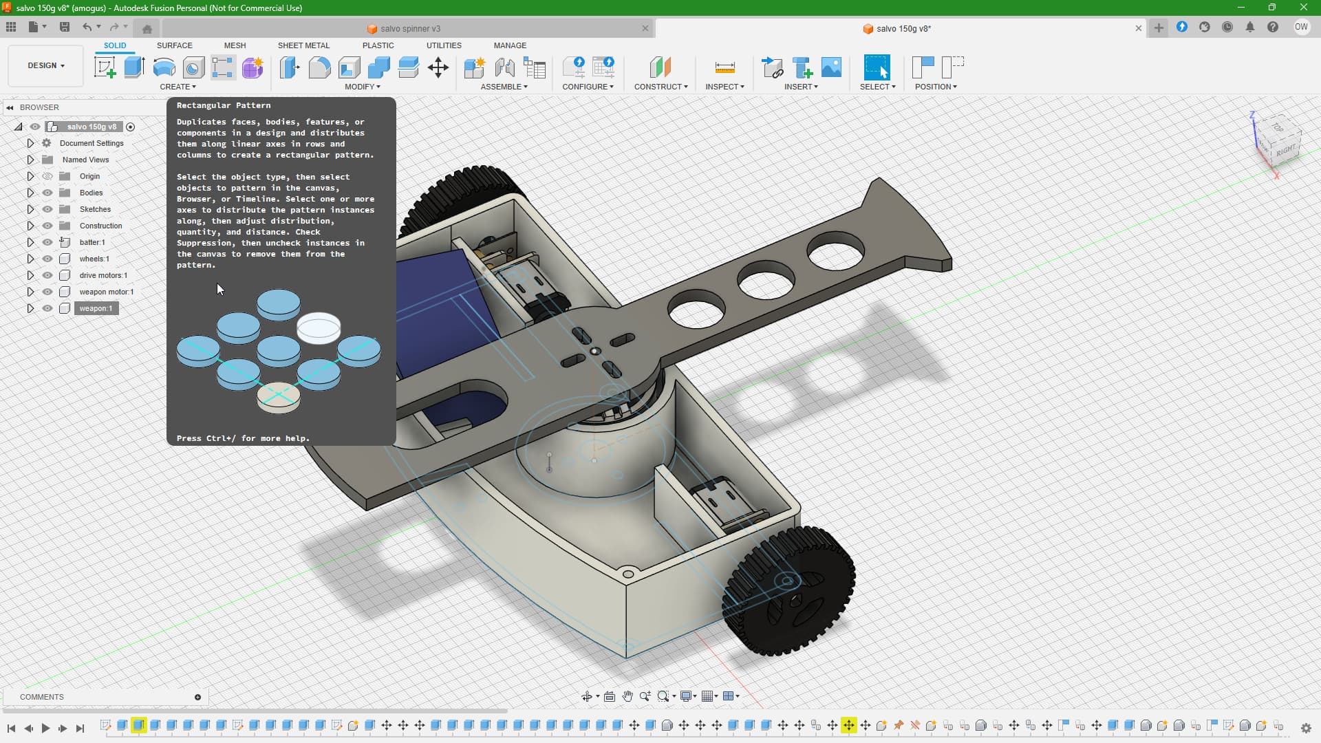
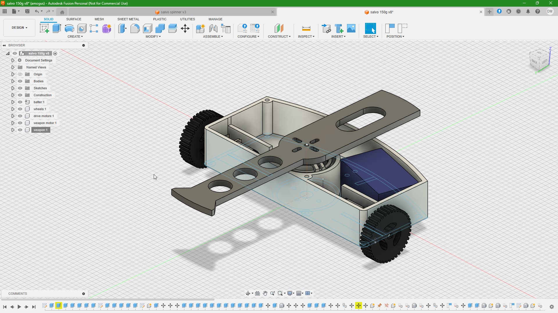
I decided to completely redo the CAD just because of how vastly overcomplicated I made the initial model.
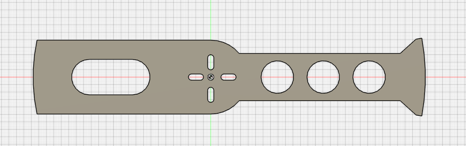
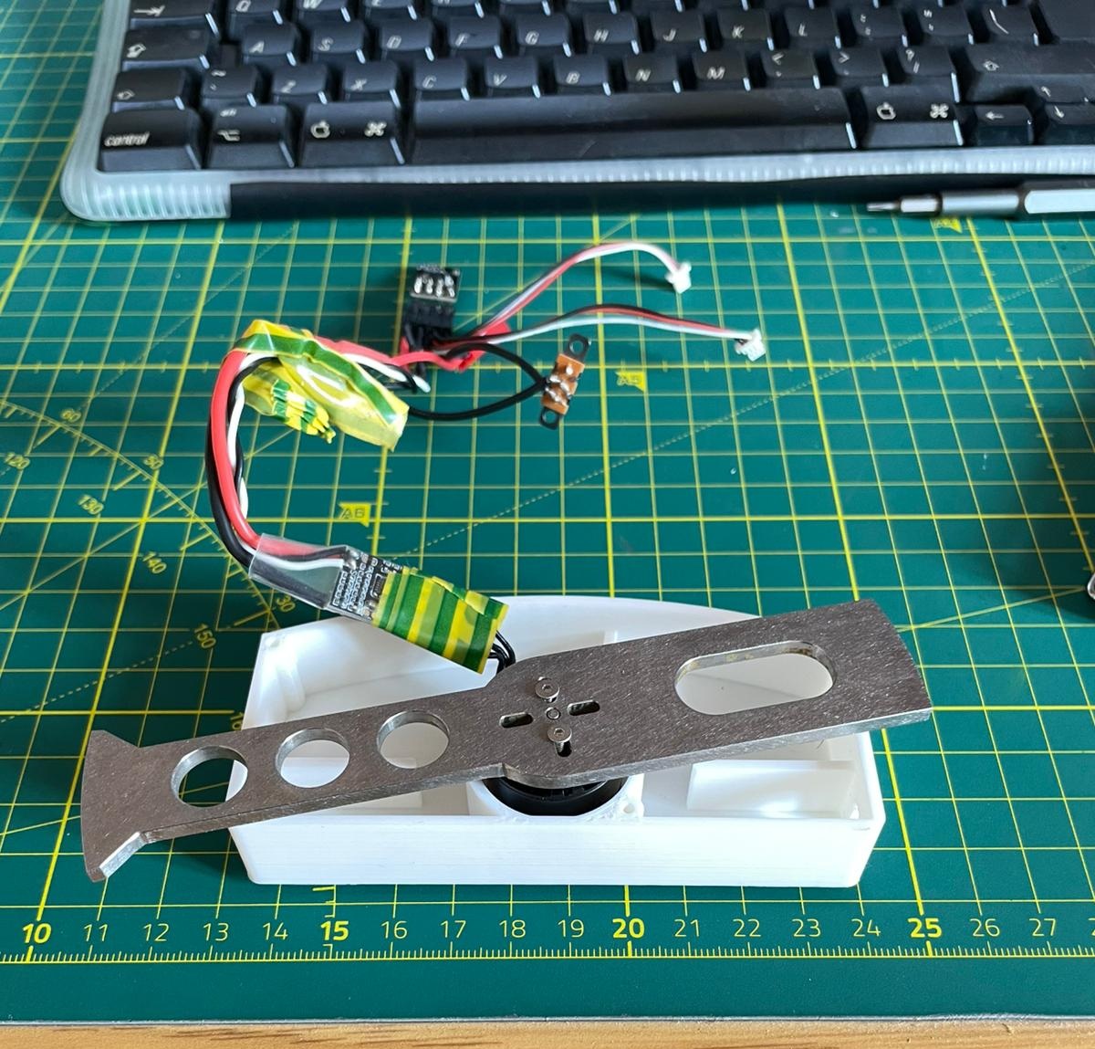
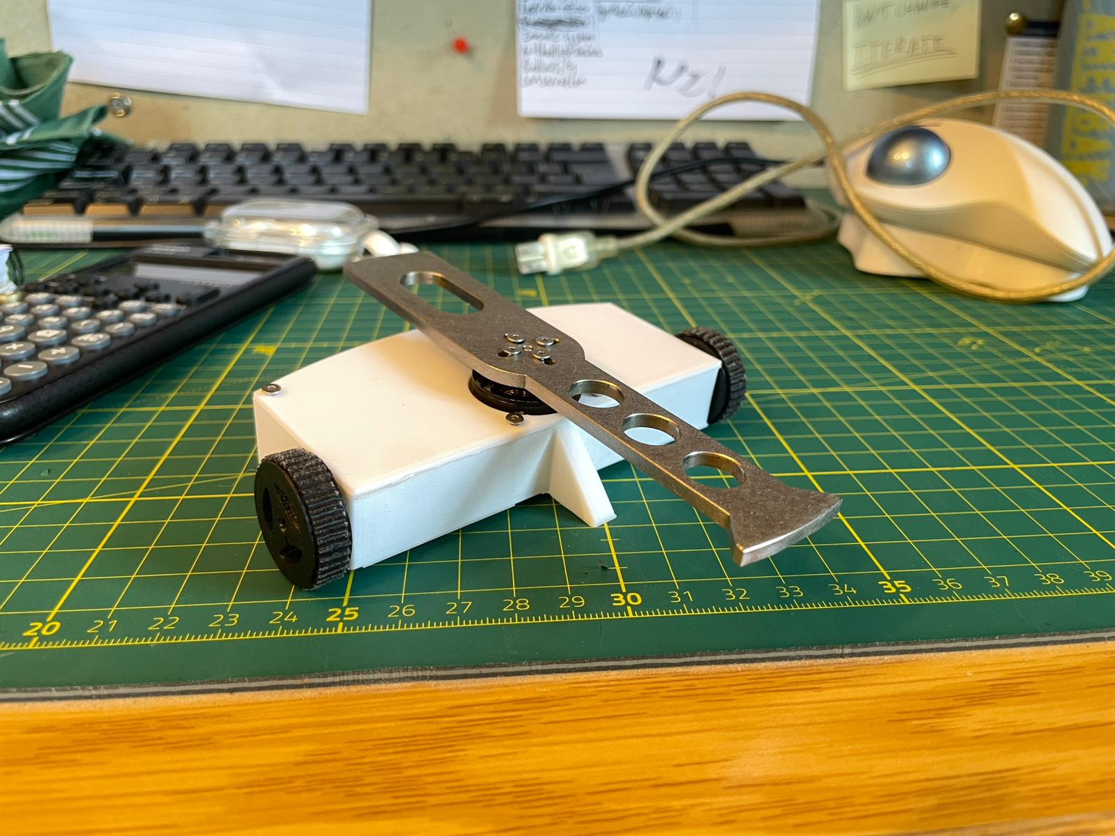
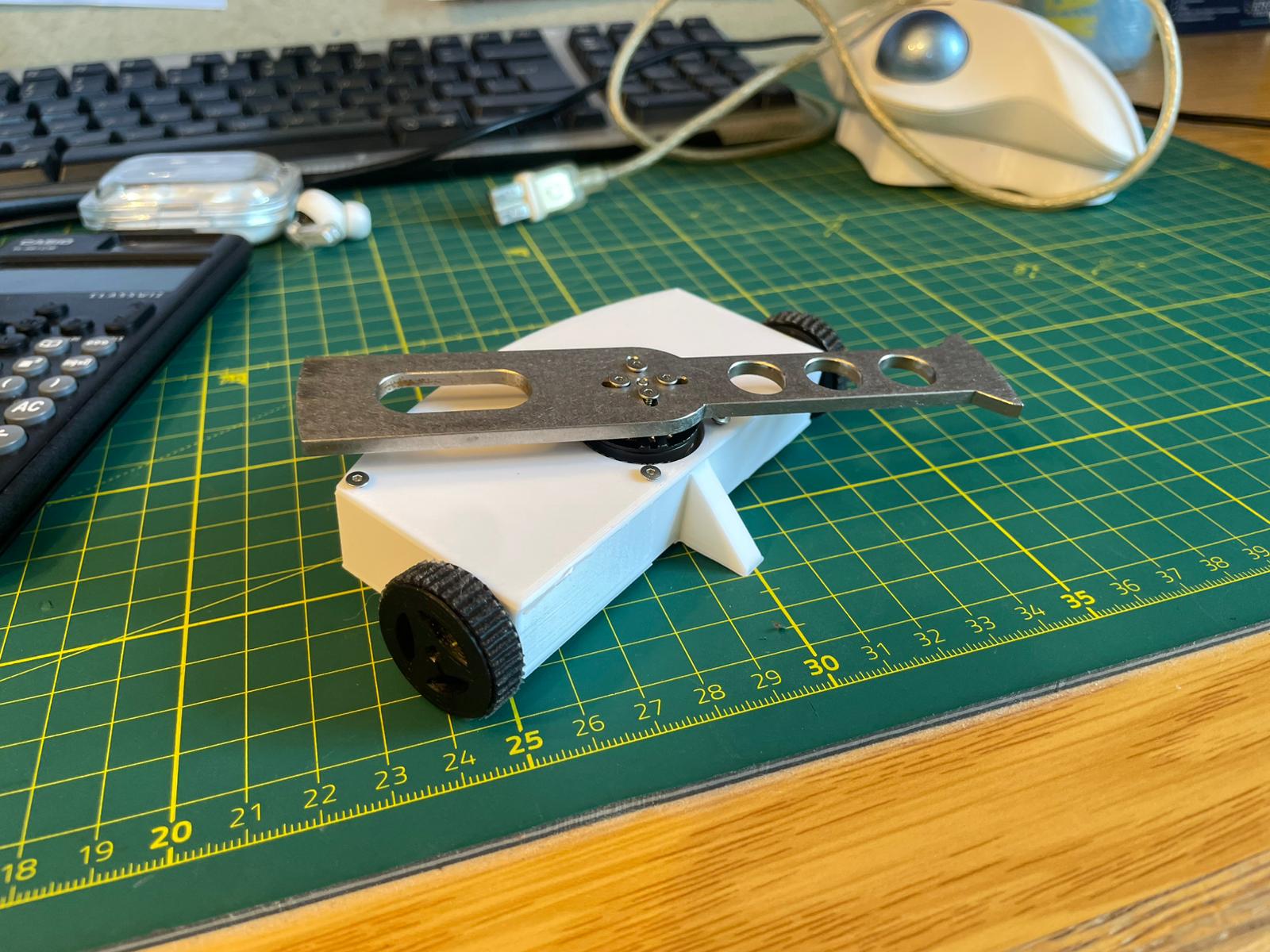
As well as this, the blade has just arrived in the post, and I’m very happy with the quality. Just as a reminder for future competitors, this puppy’s a 145mm diameter asymmetrical spinner, weighing a mega 50g (be scared). Here are some pictures for size and scale.
OS-1 (standing for Overhead Spinner no.1, inspired by the teenage engineering nomenclature) is actually looking like a proper robot, and dayum does this puppy look mean.
I’m assuming it’s going to be overweight, so will likely need to do some rather drastic weight saving - drilling holes, N10s, etc.
As for now, to get it working, all I have to do is:
Build a weapon bar locking pin
buy some batteries, N10s and o-rings
cut a slot for the switch in the lid
use tonnes of hot glue
drill holes everywhere
print smaller wheels
ziptie everything into place
test it (in a box obviously)
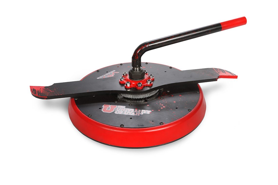
and finally change the motor shaft to make it longer. This is an (admittedly rather poor) idea for getting the thing to have some self-rightability, having seen this on basically every shell spinner to ever shell. It just means that in case I land weapon down from a flip or one of my own hits, I may be able to run the weapon to push myself back onto its front.
I attach a picture of bloodsport here which has a similar thing for what I’m going for, however, I’d keep the shaft straight (no bends as seen in the picture) for weapon balance reasons, due to the shaft also spinning.
My question is - is it possible to exchange the shaft in the BBB brushless ant spinner motor for something longer to achieve this, and If so, how?
Yup, Ernie definitely had a baby. Knowing how much those antweights bounce off the walls, you might be able to get away with not having a SRIMECH bar (definitely not so if we ever fight it’ll be easier to beat), but it’d still suggest having one. As for how to swap weapon bars, I have no clue how.
If you need weight saving advice, your overhead weapon makes you more or less invulnerable to overhead weapons so long as you can keep it spun up. Maybe you could make the top thinner, or cut some bigger holes in the weapon. The internal bulkhead between the motors and the rest of the chassis could be made smaller to reduce weight, but this’d only get you a gram or two.
Dude, If I hit the walls, I’m going THROUGH the walls.
But seriously, I would at least like to test the bar, just in case. I’m just imagining how peak it is, if I end up wrecking the other bot, only to land spinner down and not able to do anything at all.
About weight saving, I think I’m going to build the thing first, and then leave that problem for when it’s in full working order, but will definitely bear this in mind for when the time comes.
You can change shafts depending on the version of 1806 you have but it’s a bit tricky and requires a vice. You would also probably lose the circlip on the bottom which could be important for an overhead as without it your motor can could fly off under a vertical hit. It’d probably be easier to implement some sort of cone on the top of the spinner like on Kamikaze by Robert Cowan and mount it using your blade mounting hardware.