Howdy all, finally had a free weekend so getting this next part written up wasn’t too bad! Thanks for all the kind words so far, wild how many of us took such similar roads to get here ![]() Without further ado:
Without further ado:
Boom Zoom MK2
So following on from Boom Zoom’s first event, I decided to shelve MK1. It had taken an absolute beating, and I had quite a few changes I wanted to make. Rather than retrofitting these onto an already knackered chassis, the easiest course of action would be to start fresh. My list of changes included:
-
Modular front attachments including forks and a wedge
-
Better ground game
-
Sturdier front armour
-
Make the whole robot easier to work on
-
Thicker frame rails
I also went about designing and building this version in a completely different way to the last one. I hated using Sketchup, and it ran terribly on my machine. On the advice of a few other builders I made the jump to Fusion 360 as my CAD software of choice. Like Sketchup it was free, but it seemed a lot more powerful and was much more widely used by roboteers. I was recommended the excellent series of tutorial videos by David Small, where he shows how Fusion’s tool suite can be applied to combat robot designs.
")
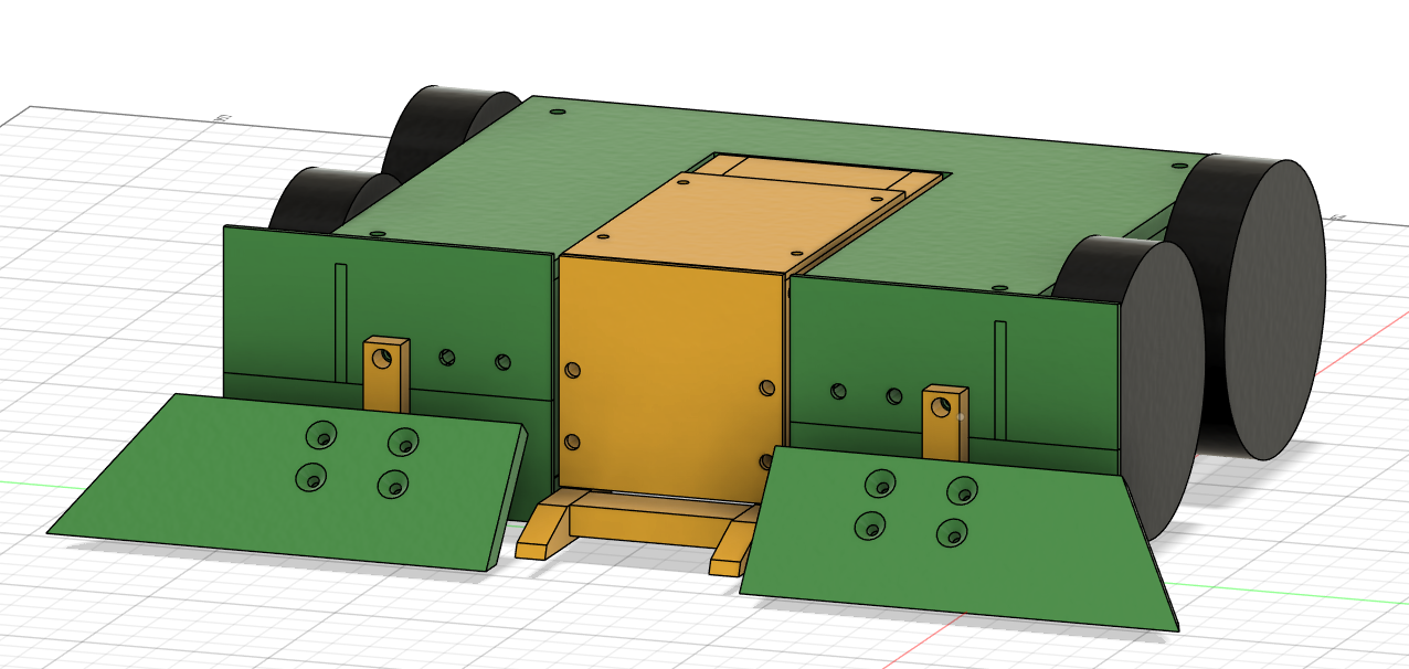
By following this tutorial, then adapting these techniques to my own design, I was able to CAD the new version of Boom Zoom in a little under a week! I found working with Fusion difficult to get my head around at first, with the sketch and extrude method of design being a big departure from how Sketchup generates shapes. That being said, by the end of this design I was a lot more comfortable with the program, and for anyone looking to get into CAD I’d highly recommend skipping Sketchup and jumping right into Fusion with David’s tutorial. Anyway, here’s what I ended up with:
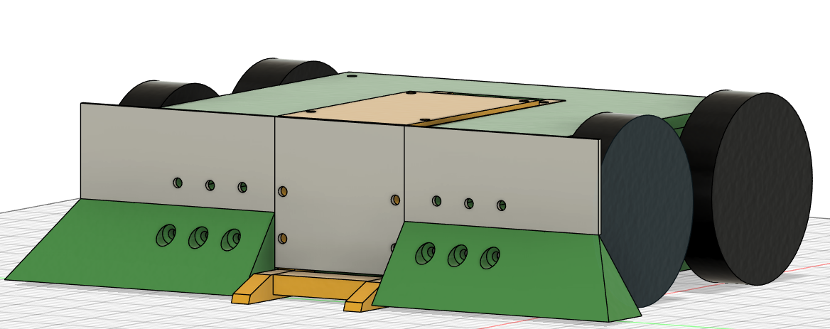
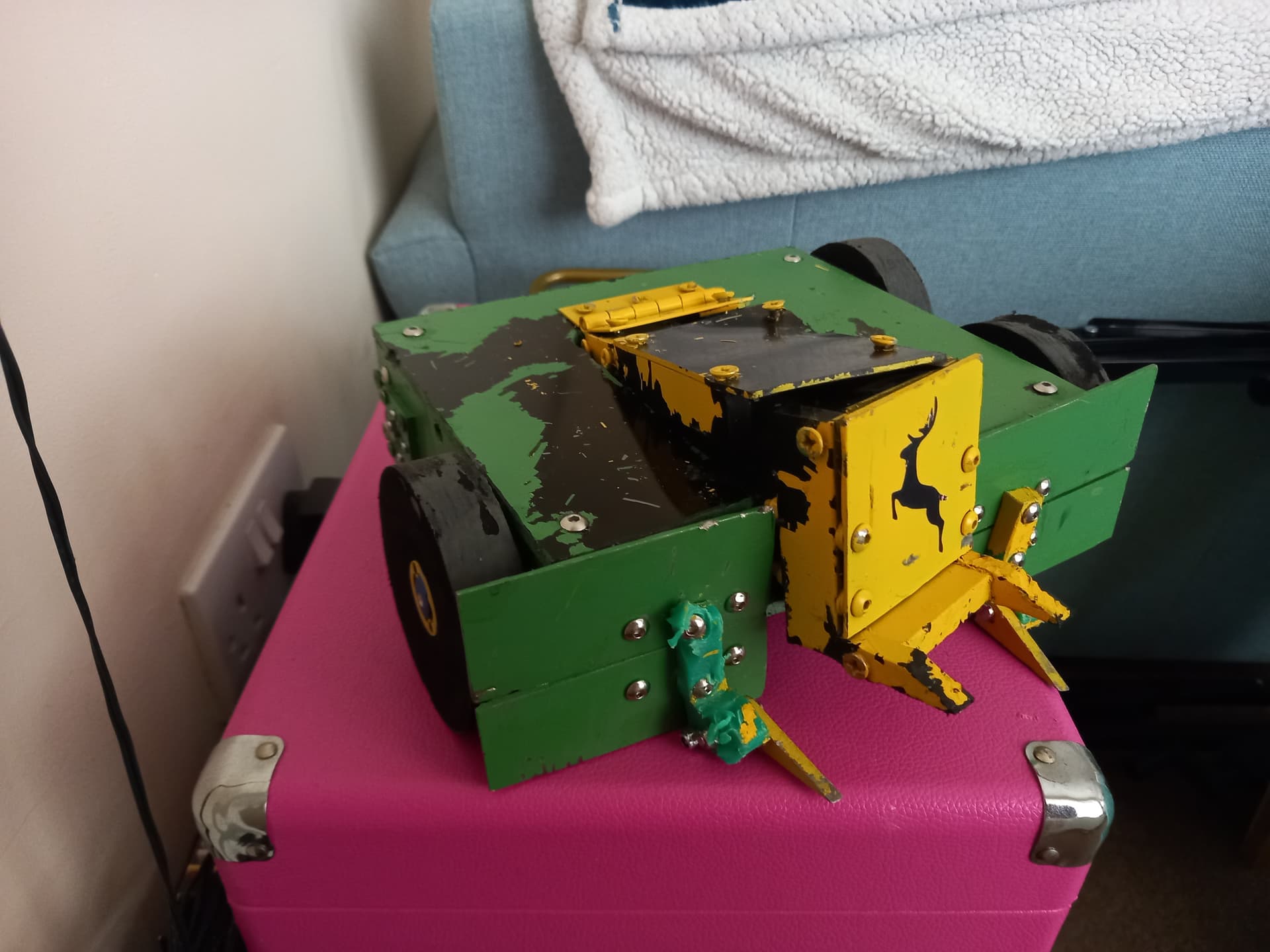
First things first, I opted to change the colour scheme to match the farming theme of the robot! My family have always gone with John Deere machines, from tractors to lawnmowers and everything in between, and no other robots were rocking this combination of colors at the time. This would go on to become my default colour scheme for all future robots. It’s nice to have a brand I guess.
Getting back to the design itself, this was already a big improvement over my first stab at CAD, as I actually had holes for fasteners this time around! In terms of design changes, I upped the side rails to 8mm HDPE, and dropped the back down to 8mm to match. I also added a full 8mm mount plate behind the front armour, the intent being that the hole pattern on this plate would support multiple front armour packages. For the default front armour I chose 2mm Grade 5 titanium, as this offered great strength for its weight and can be worked with basic power tools. For the wedge configuration I went with a 25mm piece of HDPE cut diagonally to form the angle of the wedge. For making this version I invested in a couple of power tools to make the process easier, namely an angle grinder and circular saw for cutting the titanium and HDPE respectively.
To make life a little easier, I printed 2D profiles of each panel I was cutting onto a sheet of A4, then cut these out, stuck them to the HDPE and used them as templates to cut/drill around. Between this and using the circular saw, this chassis came together much more quickly. Only once it was all together did I realize I had an issue - I’d messed up one of the motor holes, and now only 3 wheels were on the ground at any one time. This was because I’d drilled the holes with a hand drill, and one hole was at a slight angle. To fix this going forward I invested in another tool, a drill press to ensure straight holes, and recut this panel. Using the drill press to make the holes worked a lot better, and soon I had a fully together chassis with all 4 wheels on the ground.
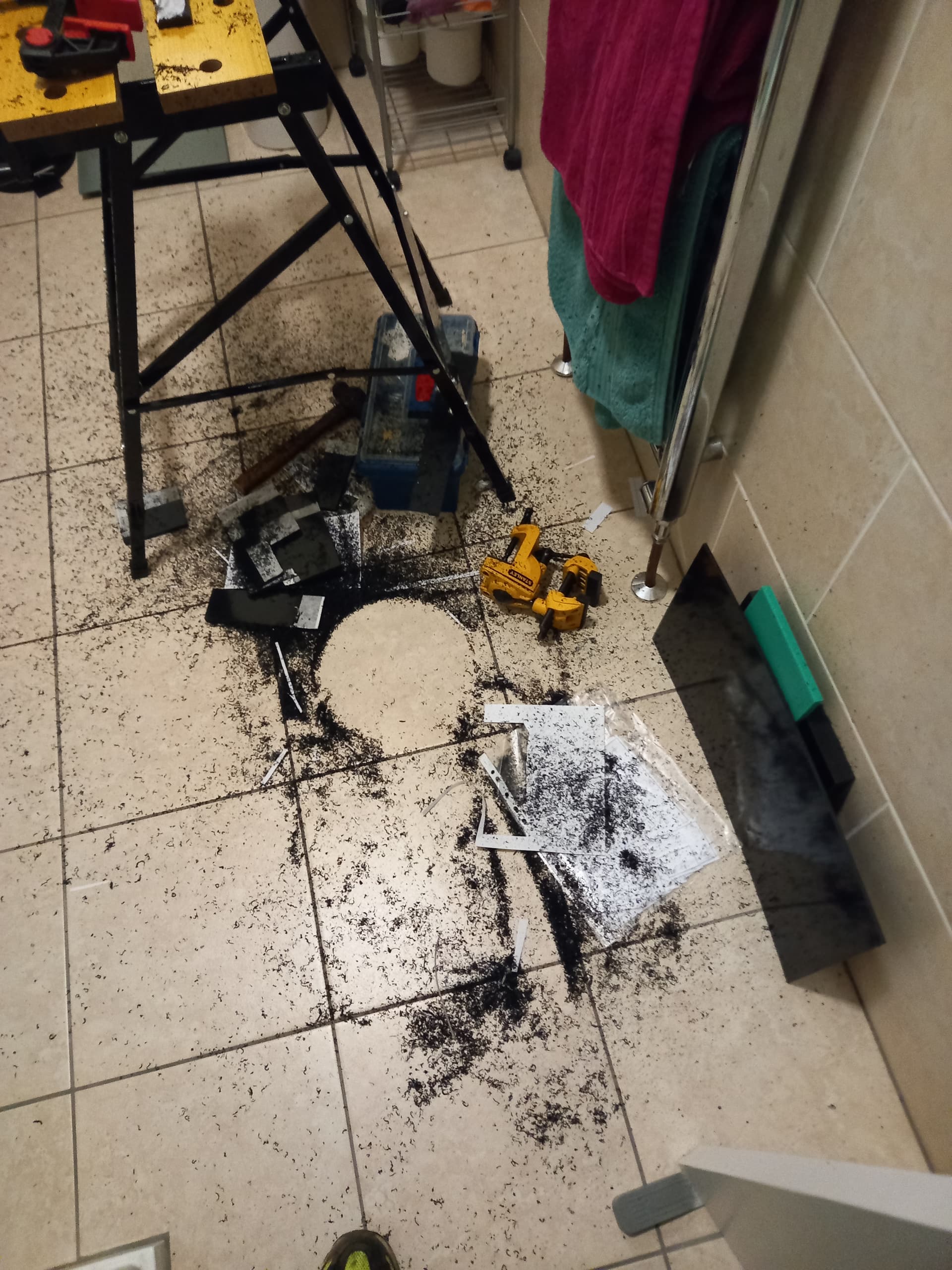
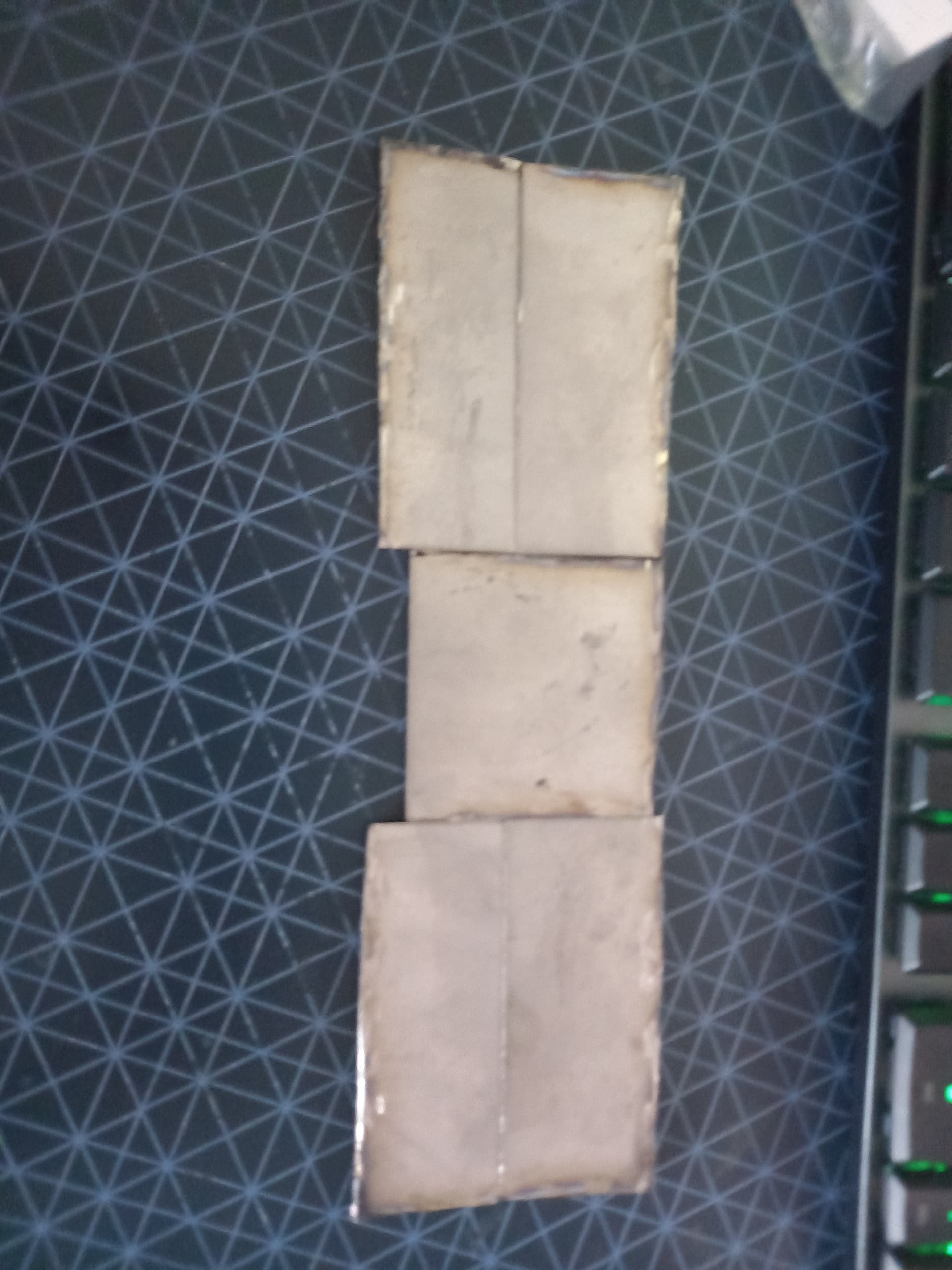
The next step was to cut the titanium! I used the same method of printing 2D profiles straight from the CAD model and gluing them to the ti, then cutting them out using my angle grinder with a cutoff disc. I then used a flap disc to clean up the pieces, and a center punch and tungsten carbide drill bits to bore out the mounting holes.I mounted these to the chassis with M4 bolts and nylock nuts, with a few rubber washers between the armour and chassis to provide some shock absorption.
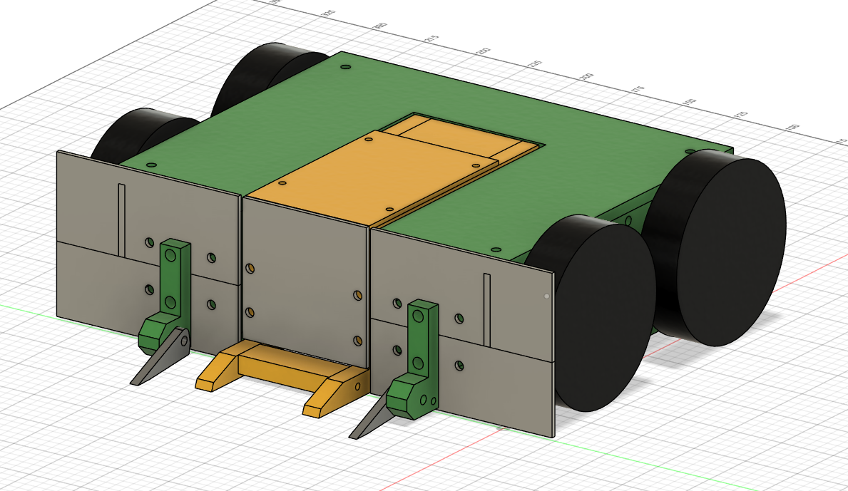
For the forks, I sent a dxf of the 2d profile I wanted cutting over to Sion, who was kind enough to hook me up as part of a group order with KCut. The forks were waterjet cut out of 4mm Hardox, and with a little dremelling ended up fitting very nicely. The mounts are designed to be easy to make, disposable and ablative, as well as having downward travel limits built in to prevent the forks folding under the robot and immobilizing it.
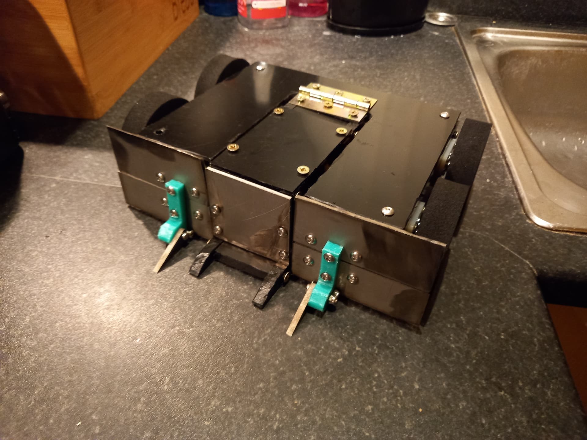
I then cut the wedge, once again with the circular saw. I wasn’t entirely happy with how these came out though, as the wedge was way off the ground and I thought it’d leave the robot vulnerable to undercutters or horizontals with ground game of their own. I got around this by designing an alternate wedge config out of 6mm HDPE, with a hinged element that rested on the floor.
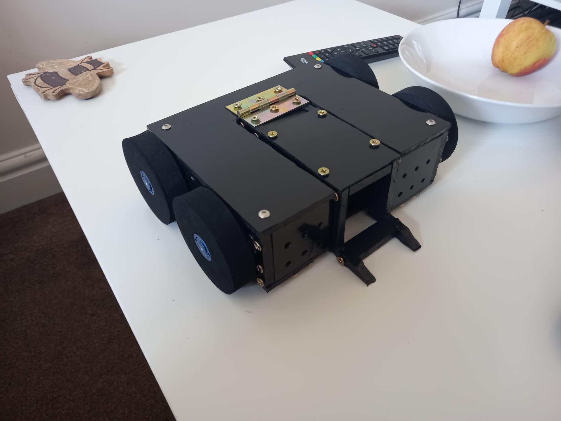
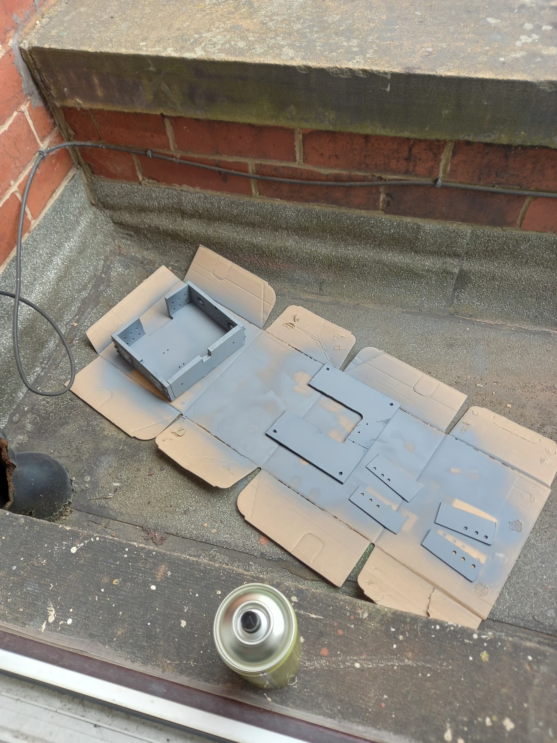
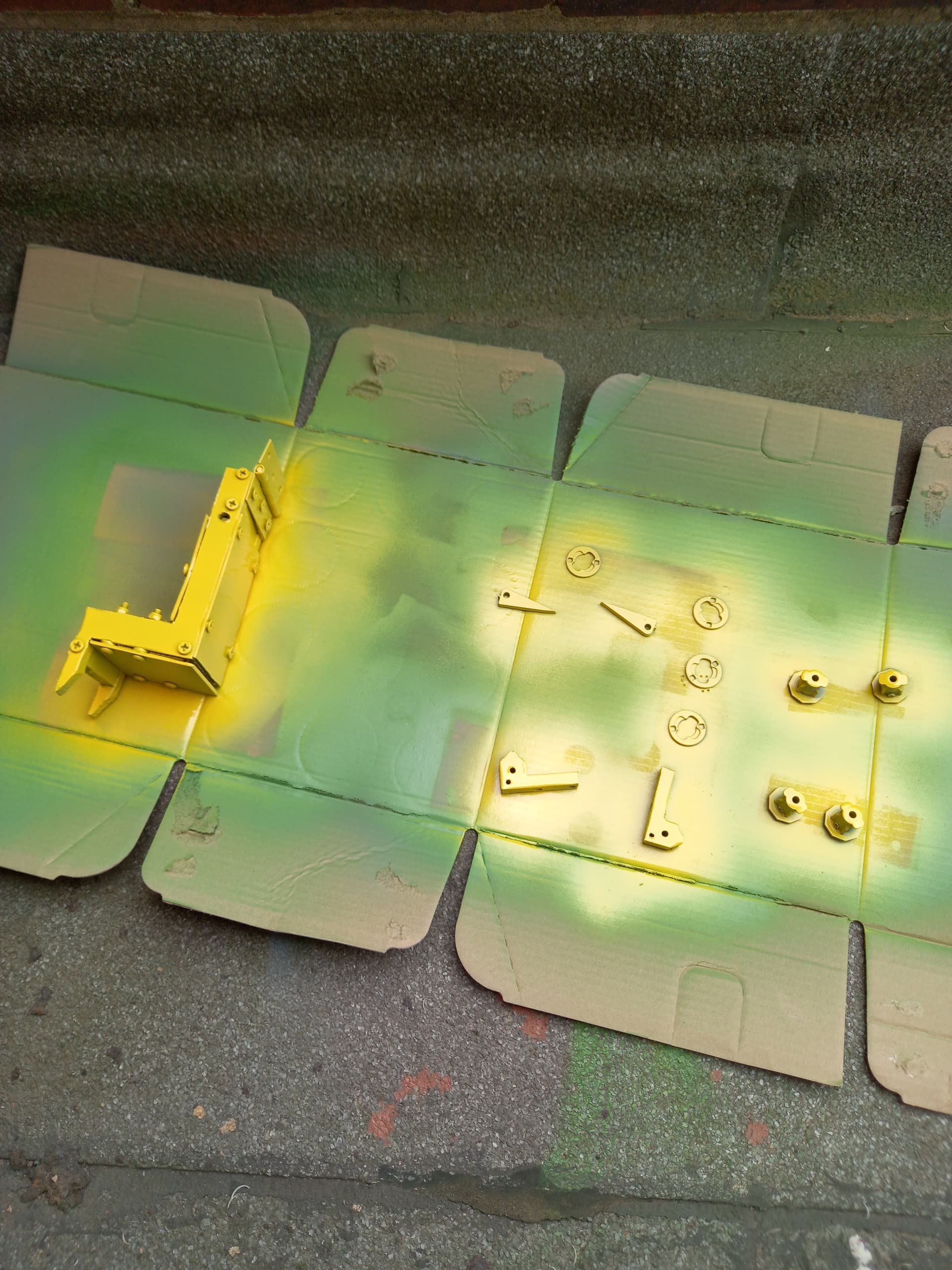
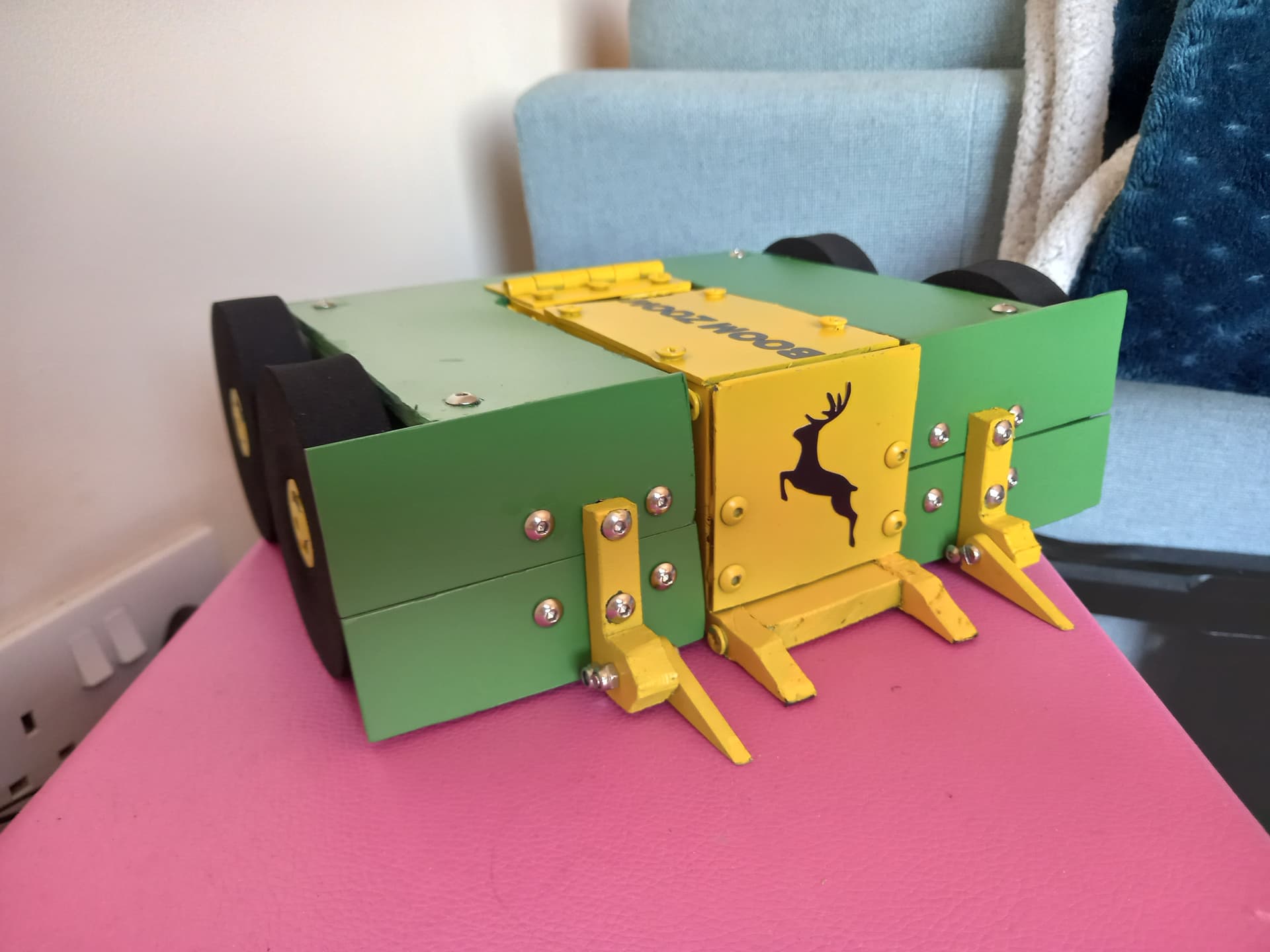
At this point, the chassis was about done but looking a little drab. I took it apart and began spray-painting, first doing a coat of gray primer, then green and yellow over the relevant parts. I gave the twist hubs for the wheels a coat of yellow as well for good measure. Overall I was pretty happy with the effect, but found the paint flaked off the HDPE very easily, even during gentle handling of the robot. I finished the cosmetics by adding a big John Deere logo vinyl sticker and the name of the robot along the lifting arm, both cut by my partner.
For the electronics, I cut out the core of my previous wiring and replaced it with a BBB breakout cable, with every single part of the robot on some kind of connector to make swapping them out easier. I also swapped out the battery for a smaller 4S 450mah pack, saving a few grams over the old one.
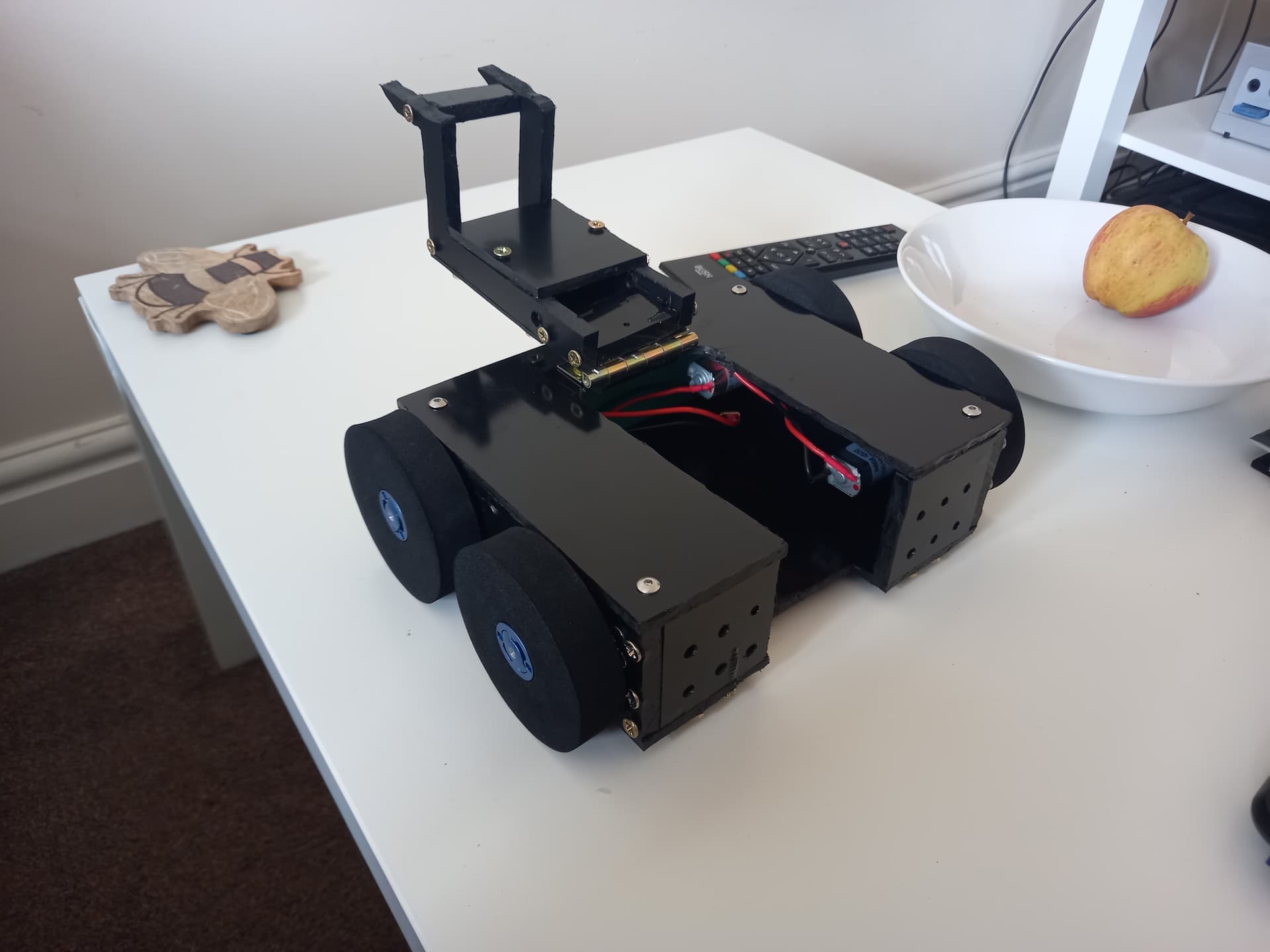
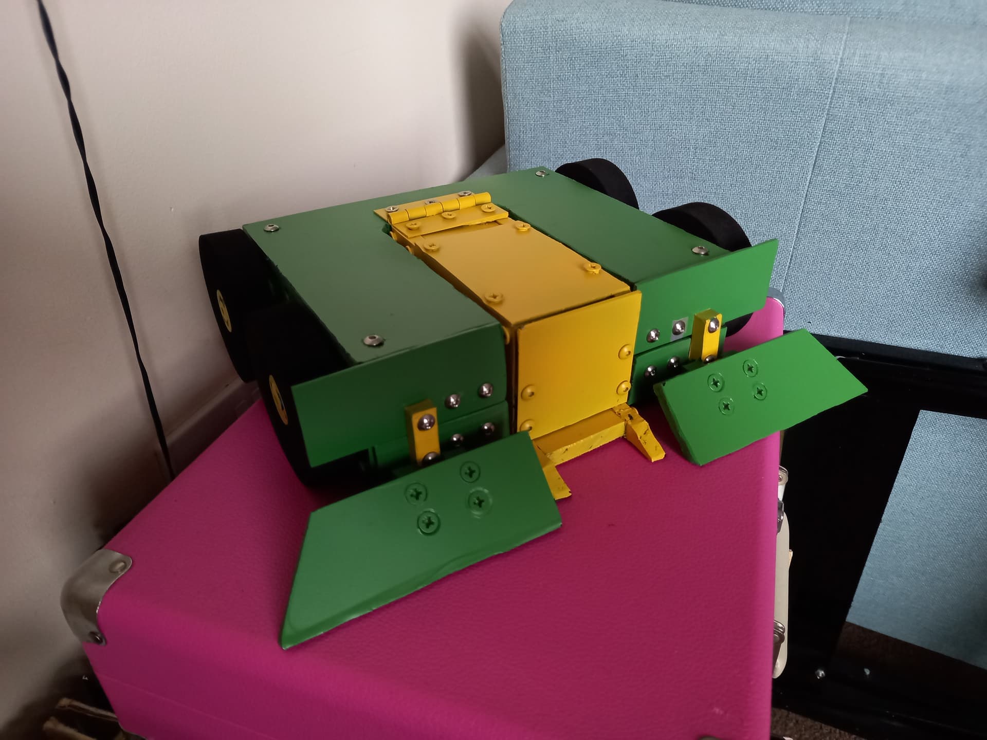
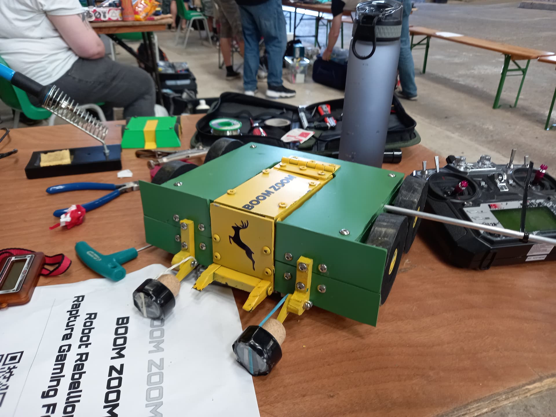
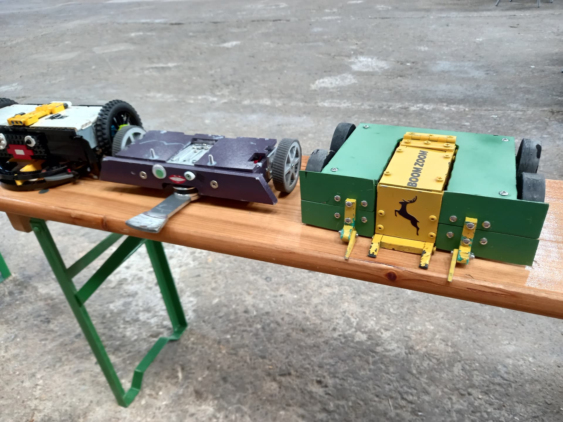
With all this done and the robot together, it was time to snap a few beauty shots:
I already had an event in mind for Boom Zoom MK2: Rapture Gaming Festival. This is seen as one of the biggest events of the beetleweight calendar, and usually attracts a very high standard of robot. Given the fact my last robot had been written off by the very first spinner it faced I was a bag of nerves going into this one.

Anyway, here’s how it went. My fights are at 1:18, 23:57, 50:49, 1:55:29, 2:38:03, and 2:55:15. The new forks worked well against Brug, This Is Not A Drill and Rust In Pieces, allowing me to manoeuvre them around and overturn them successfully. My fight with TINAD in particular was a fantastic driving match and a tense JD, with my drive starting to lock up towards the end of the fight. I later found out this was due to the twist hub working its way down the motor shaft, causing the wheel to rub against the chassis. This was easily fixed by moving the hub back down the shaft and re-tightening the set screw. My fight against Let The Good Times Stroll worried me, it had an insanely powerful weapon that could knock out a robot in one hit if it got a good connection. I got very lucky in Stroll not being able to move forward properly, allowing me to pin it against the wall and overturn it, bending the weapon assembly and causing a massive ESC fire which won me the fight! I was surprised my 30KG servo could handle overturning a 2KG robot like Stroll, and elated to have won my heat without taking any damage!
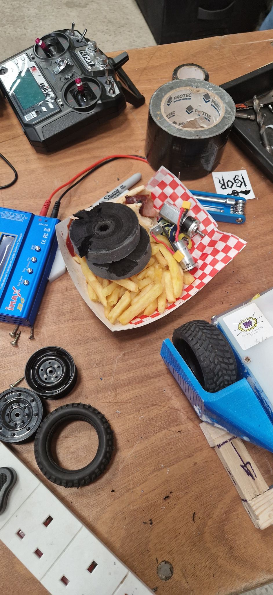
My round of 16 fight was against Night Fury, and here is where I encountered the first problem with my modular fronts: they took FOREVER to swap. Removing and redoing 6 nylock bolts per side took an absolute age on my own, thankfully Andy offered a hand with his electric screwdriver which sped up the process immensely and meant I was ready in time for my fight. Fat lot of good it did me! Night Fury’s sharp, thin blade cut through my HDPE wedge like butter, got around to my side and took out an entire drive side, exploding the motors with direct hits to the wheel hubs. Getting beached on my own shredded wheel and counted out was a mercy really, and once again a horizontal spinner had completely outclassed Boom Zoom.
This time though the bot was not written off! I was able to swap out the ruined wedge, wheels and motors and get the robot back together in time for a 10 robot rumble to close out the day. This was a weird one, for starters the lifter elastic came undone almost immediately, then a short way into the fight my robot seemed to kind of die when gently pushed into a corner. It’d continue to twitch and briefly respond to input at points, but it was effectively immobilised. The robot worked fine after unplugging the link and plugging it back in, and I’ve never had this issue again with any of my robots. Things went from bad to worse when BFM landed on top of Boom Zoom, snapping the lifter arm in 2 places and knocking the servo loose from its mounting bracket. This damage was catastrophic for this version of the robot, and would require an entirely new lifting arm as well as replacing several other damaged components from the rumble.
For this reason I decided to once again go back to the drawing board and redesign the robot, but this time I’d been chatting with loads of builders at the event, getting pictures of the insides of their bots and making notes of ideas I’d like to try in my own build. I was very happy with how MK2 had performed, all the changes I’d made since MK1 had played a part in making it a better robot (except maybe the wedge) but I had a clear vision of the direction I wanted to go with the robot and felt ready to take the next step in its development. Tune in next time for what I consider the single biggest step up in this robot’s development cycle: Boom Zoom MK3!