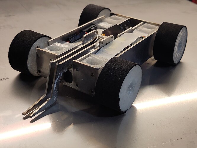
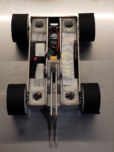
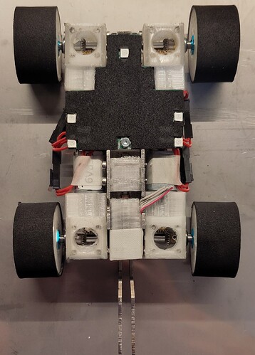
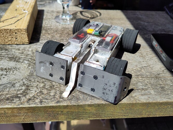
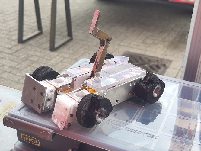
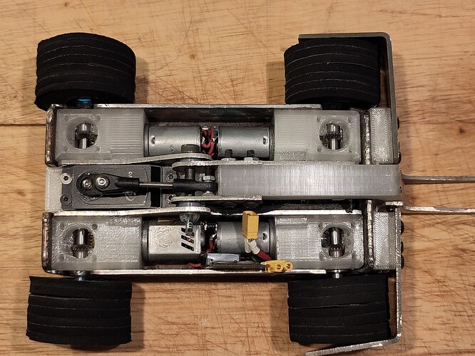
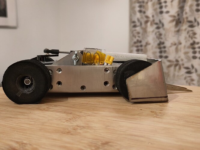
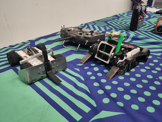
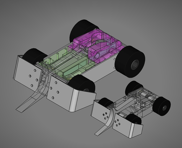
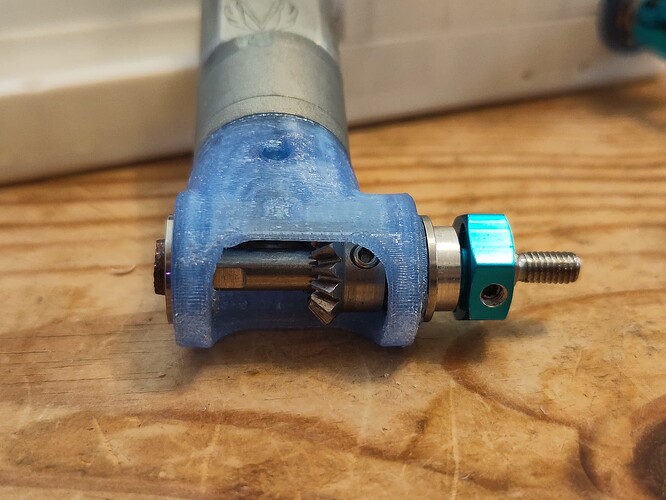
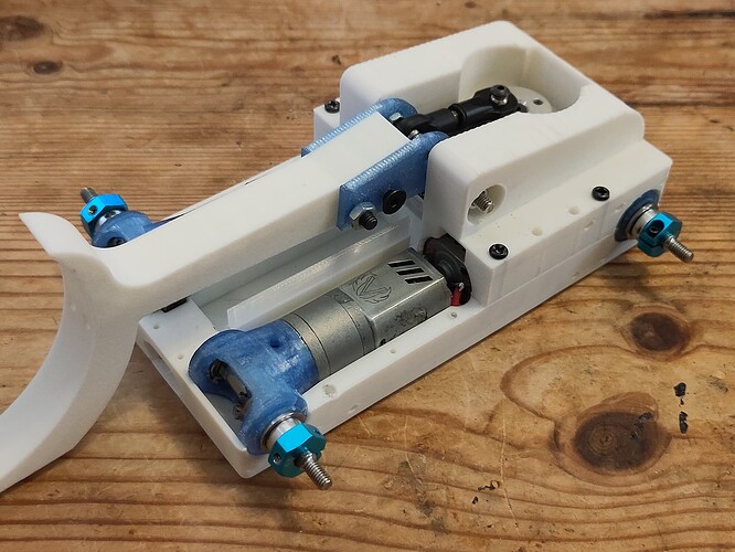
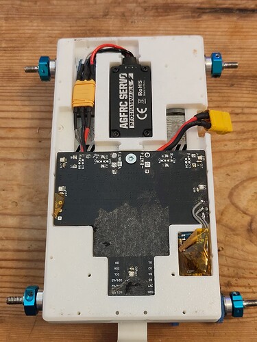
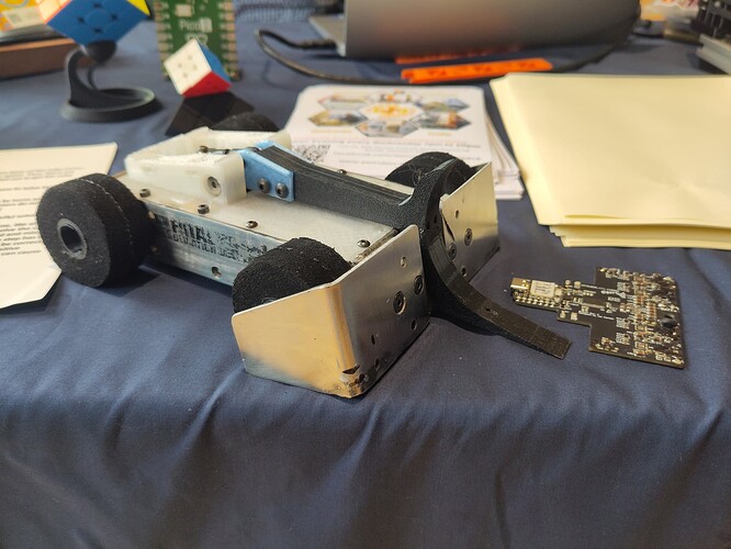
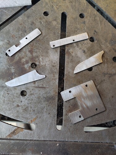
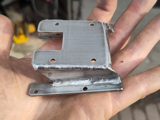
Alas, I’m using 130 motors and the 180s are too long. Those nerf motors are a shout though, those are some ludicrous stall current numbers for a brushed motor that size. Apparently a colleague is into his nerf modding, so I’m off on the scrounge before I buy anything…
I bought some of the Out of Darts Valkyrie motors and they arrived yesterday. Straight swap for the aliexpress ones and I feel like they should perform great, except when starting out they pull more current than my little Allegro A4950E 3.5A drivers can supply and trip the internal over-current protection.
I’m going to throw my hat in the ring for the pub beetle event in May, if I get a spot I guess it’s rev2 PCB time and I’m spinning my own motor drivers. I also think the aliexpress motors might behave more acceptably at 4s (or more), but I need to do some testing as that means more current draw while switching the intended 530mAh battery for something with less capacity.
As it stands, here’s how it performs with the aliexpress motors running on 3s: https://www.youtube.com/watch?v=Y6qvmATpInE
Turns out I’m fighting on the 25th, so basically all my time spent not at work or asleep has been robot related. Current status:
(infodump below)
Drive is mostly done. The gearboxes took a lot of fettling to get gear mesh just right (and repeatable) and the parts easy to fabricate. I switched to 6V motors and the bot now scoots about happily at a speed that’s actually fun to drive. They don’t get too warm so I don’t think they’re going to explode but I’ve put connectors on the wires anyway, because if I make it easy to service they’re guaranteed to survive, while if I hard wire them that’s just asking for a failure.
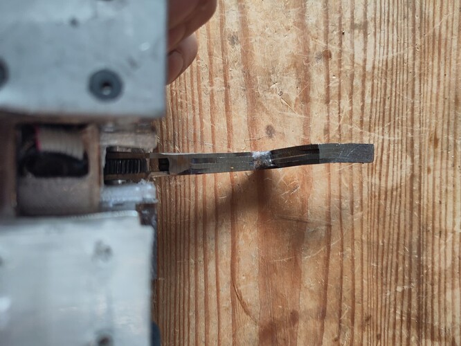
The weapon assembly needs more machining work, it’s getting a couple of bulkheads to sandwich the worm gear onto the motor shaft and handle the forces of lifting, and also to keep it from shooting into the battery pack with just the right impact to the lifter. I’m making the parts from brass because I have broken so many drills already this project I can’t even
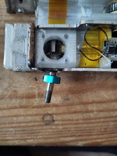
The weapon motor tucked in there is some aliexpress weirdness (the listing literally says “we don’t know anything else, please don’t ask us about it” but I managed to find the datasheet), it’s an in-runner brushless motor that happens to fit on a gearbox from a 16mm gear motor with a little persuasion. It also has a hall effect sensor, so I can get arm position in my software for free with no extra parts. Napkin maths and trusting the datasheet say I get roughly 40kg/cm of usable torque (60ish stall) at the arm pivot while taking about half a second to rotate 90 degrees to vertical (not at the same time).
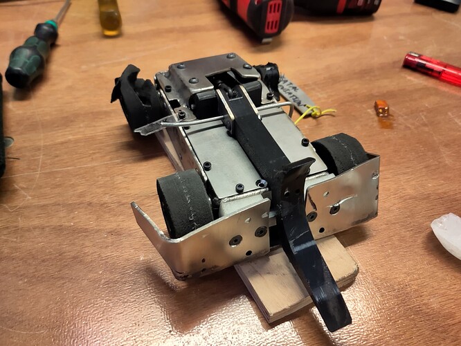
I’m slowly running out of internal space, and that was kind of the plan all along. Any space not filled with Stuff gets chunks of foam and (if possible) some low-infill TPU inserts.
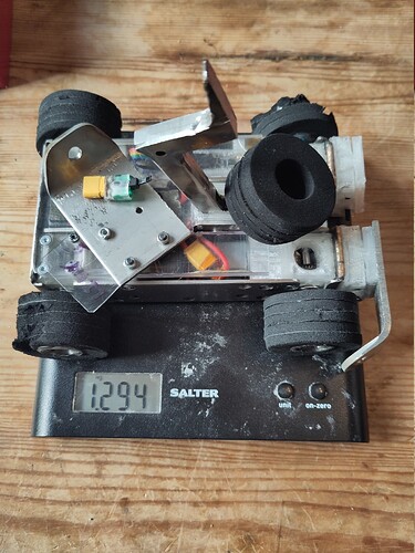
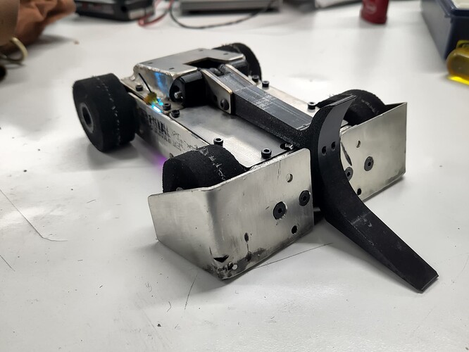
Also, weight check: As pictured, 945g.
I love this. It’s a great combination of a minimalist design in some ways (right angles, symmetry) mixed in with some outrageous over-engineering (welded unibody and custom PCBs). The build quality is lush, great to see that welded body, and glad it’s come out fun to drive.
(On the subject of over-engineering, I kinda feel like this whole hobby is by definition over-engineering since none of us get paid for this or achieve anything other than our own satisfaction. I do boring “proper” engineering as a day job, building robots is where I do stupid unnecessary engineering just for the hell of it.)
Thanks! I was pondering the concept of over-engineering as I rushed to finish assembling my robot in the minutes before my first fight and cursing some fiddly design choices, and I think it’s when the intricacy of the design gets in the way of assembling and using the damn thing…
I actually took some days off work to finish this thing, finishing the last parts at 11am and only getting the robot assembled minutes before the first fight (I went in with only five screws out of a possible 30+, although I never intended to use every single one that’s cutting it a bit fine).
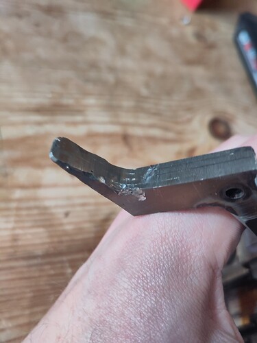
I will do a proper damage post-mortem when I’ve returned to a reality that doesn’t entirely revolve around robots, but in the mean time here’s a before and after photo:
I came into the first fight with no weapon at all - the pinion (pulled off the motor that the gearbox came with and pressed onto the little brushless one) was spinning free on the shaft, and it bit me when I ended up stuck balanced on the lifter arm leaning against the side of the box. Loss 1.
Fight 2 was possibly the most pathetic win in combat robotics. I was up against a beautiful lead screw driven crusher that I’ve already forgotten the name of. I was struggling with some drive bugs (don’t update code the night before the event, kids), so I was an easy target for a couple of good pins, but luckily he only managed to puncture the TPU wedge mounts a couple of times before his battery died. The sensible thing would have been to drive laps of the arena, but seeing him crawling forwards slowly I thought I had an easy shot for some cheeky battering ram action. What instead happened was I hit the bot slightly off centre, flipped over, and was left spinning around upside down, stuck on my too-thick lid which didn’t fit properly, next to my now totally immobilised opponent. Win 1, because he stopped moving first, just.
Fight 3 was against my pit neighbour Forkhead. I lost the ground game on the first head on collision, rode perfectly up his forks (spaced exactly the same as my wheels’ track width), and ended up cradled in the lifter for an easy suplex. Again, stuck upside down. This time I held the lid down with some screws into the bulkhead, and of course got stuck on those instead. Loss 2.
Fight 4 was a whiteboard fight, I asked for a vertical spinner with a high chance of roofing but none were available, so instead we had a four way rumble with three non-kinetics and New York Slice. This fight was for testing purposes, so I spent the whole time throwing myself into his weapon as much as possible. The noise the steel tub made both on impacts and being thrown into the walls was fantastic, and while I lost a wedge, it was only held on by 4x M3 nuts in TPU anyway (and I’d have welded in some reinforcements to tie both sides together if I hadn’t left my argon tank open all night and leaked £50 worth of gas away into the atmosphere). I made sure to reverse into the weapon a few times too, which resulted in just a couple of small scratches on the tub (right through my sticker oi). Once New York Slice ended up in the pit I turned my attention to the other bots, and somehow got a few good pins in - going to have to re-watch the fight to see how much skill was involved there. I even managed to get a few lifts in for the first time, proving that I do indeed actually have a weapon. I ended the fight with a bent axle leading to only three wheel drive, but still mobile with a mostly functional weapon (it lost home and was stuck waving around in the air but otherwise fully operational). The crowd couldn’t decide a winner for this one, so I guess everyone wins?
All in all, very happy with my performance here for my first time out. I had a mostly operational robot at the start and end of every fight, I got a feel for driving in the arena (somehow very different to my experience racing RC cars), and being at an event in general. I’m glad I got that last fight in, as going the distance against a really destructive and reliable spinner was a great confidence boost. I actually came into this event under-weight (exact number TBC), so there’s lots of future scope to make this bot even more of a tank.
Thanks to the BBB crew (and LHG) for putting on a great event, and thanks to the other builders too! While I was furiously assembling my bot for the first fight I had three or four offers of help, and some really good compliments and advice about my bot. Great vibe and I’ll be back for sure. I won’t rest until I hear this bot hit the roof.
Update: Weighed the bot as it went into the arena (kind of…) and it’s not even 1300g. I’ve already got some ideas on how to improve the drive and weapon that don’t require much extra weight, so I’m practically giddy at the thought of putting almost all the remaining 200g into armour and throwing it straight into the face of the nearest kinetic weapon again to see what breaks first.
Some damage photos below:
Since I’m off to the champs in October I thought I’d make another progress update on upgrades since the last event.
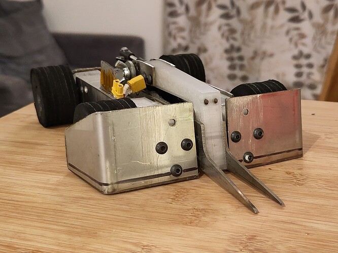
Weight as pictured is about 1350g. Most obvious updates are the new wedge and weapon assembly, but I’ve also upgraded the drive and have new electronics on the way. Keen eyed readers may notice that the front of the bot is now the back of the bot due to the weapon design. I think this is ultimately a benefit, as now the lifter arm protects the battery some, and the extra length helps with self righting.
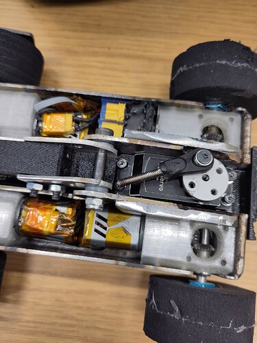
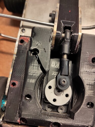
I gave up on the custom weapon gearbox and used a low profile hobby servo and a linkage. It now actually works! Unfortunately I can’t find a low profile servo that will run happily on 3s, so I have to use a buck converter to step the voltage down for this one, but I have designed and ordered some retrofit 3/4s capable drive boards that I’m hoping will solve that problem. The arm is now TPU, but with a couple of lengths of piano wire pushed through as stiffeners (and to mess with overhead saws aiming for the one exposed squishy bit). I’m also going to enclose the mechanism with new bulkheads but I’m so done with drilling holes in stainless that I’m putting it off as long as possible.
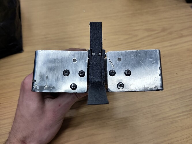
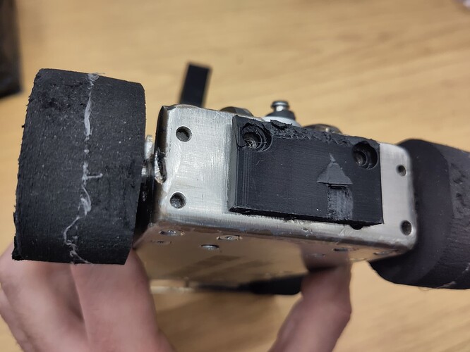
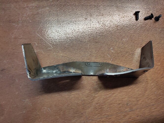
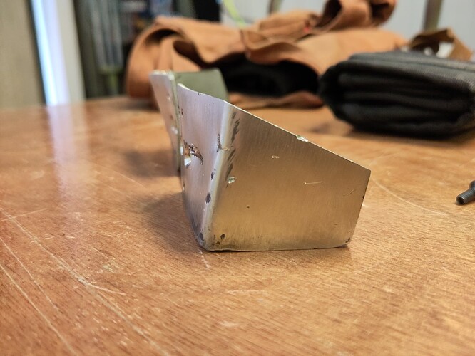
The wedge now uses threaded aluminium inserts that slide into a TPU block on the front of the bot, so it’s still shock mounted but more securely than previously. Now only 2mm, but I will be welding both sides together with a brace under the bot, so it’s going to be as stout as I can manage.
Drive is now via 4x Out of Darts Valkyrie motors on 22:1 gearboxes. Despite the power limitations of the current electronics it drives really well, hitting a decent top speed well within the confines of my beetle arena sized kitchen floor and with enough torque to break traction on carpet tiles. The bevel gearbox assembly is the only part from the pub beetles iteration of this bot that hasn’t significantly changed.
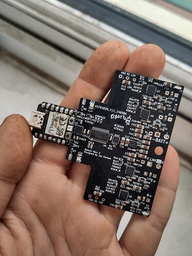
New drive electronics have been ordered! Rev1 could only manage 3.5A per channel, which causes these Nerf motors to stall when loaded and the drivers to overheat after a couple of minutes driving. Rev2 can now handle 6.5A per channel, and also has an IMU in case I want to integrate the accelerometer or gyroscope into my control or logging.
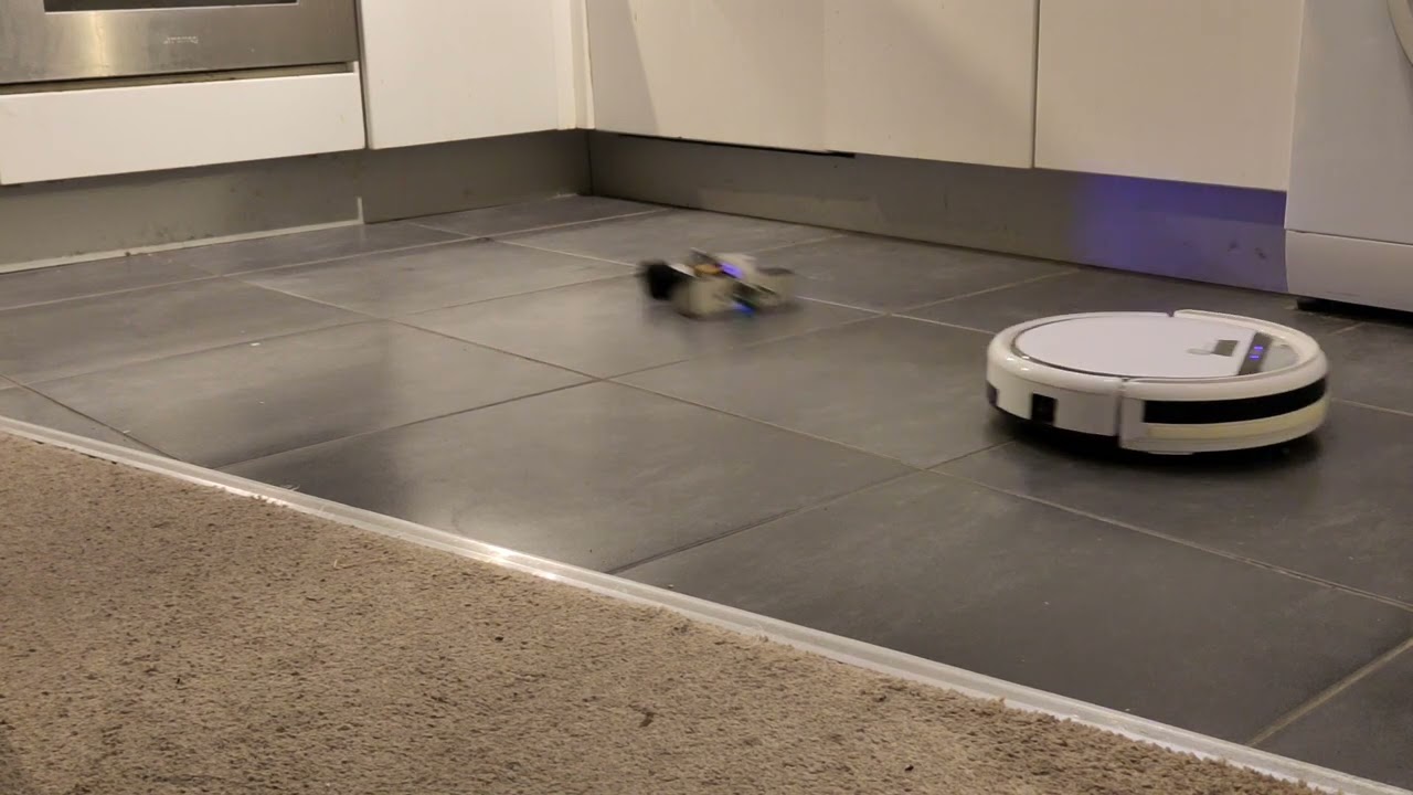
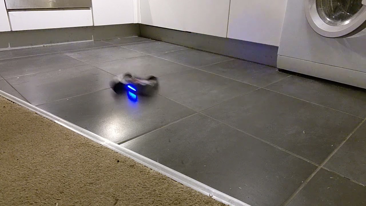
Finally, a quick video of some Roomba (clone) abuse. Unfortunately the servo screws pulled out of the (already stripped) TPU after giving the roomba some aggressive tapping, but I’m really happy that I can get reliable lifts on a 2.2kg robot. I mentioned in my Champs application that I’m doing torque vectoring, I’m still figuring out the maths but you can maybe see a little bit of it in action in this video; in fast turns the inside front wheel brakes, drifting the rear out and pivoting the bot around the braked wheel. It’s all a lot to figure out because I have to figure out how to programme it and drive it at the same time!
Very happy with how it’s coming together. It’s driving well, the weapon works, and despite crashing it a lot I haven’t done much damage. Also, the new wedge really gives the bot a strong silhouette for the audience to see hitting the arena roof.
New PCBs are in! So far everything seems to work, zero bodge wires required and I think only one silkscreen bug. I paid extra for black solder mask - it doubled the cost to £2.50 per bare board.
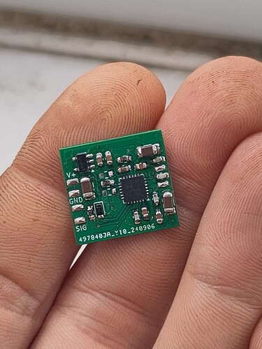
After blowing up all my hobby servos seeing if they were reliable at 3s, I determined that they weren’t, so I designed a retrofit driver board with the same motor driver as the drive PCB and an attiny85. Tested and working with a deadbugged Arduino nano in place of the attiny, it, should be good up to at least 4s, but I can’t use them in the bot til I programme the attinys and I don’t seem to have a programmer to hand.
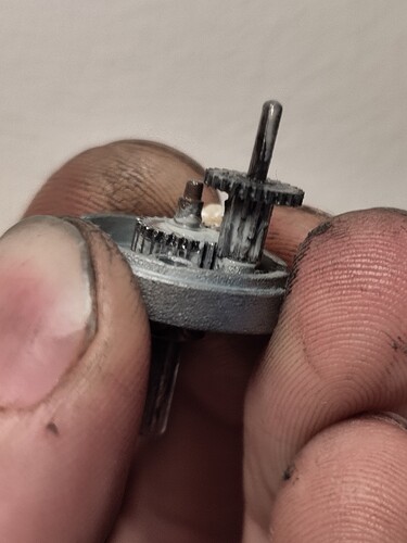
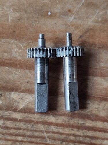
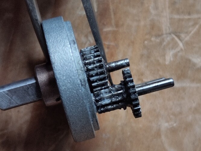
I also had some reliability and noise issues with the aliexpress gearboxes on the nerf motors. After a quick teardown I determined that there’s hardly any overlap between the output gear and its driver. On a couple of motors I’d chipped, stripped or totally cracked this driver gear in half so I had to fix it. Have I mentioned that due to my insane packaging requirements, these are the only gearboxes I can fit in this robot?
The back of the input shaft has a step down that runs inside a small bushing in the centre of the gearbox casing, so if I chuck the input shaft in a drill and give it some love with a needle file I can reduce the diameter so it’s uniform down the whole length.
Roughly 2mm worth of shims later we have full mesh, and the gearbox goes back together the way it should! These gearboxes look like they could be configured for this kind of engagement with a different gear arrangement and gearbox housing, and the shaft even looks to have a second bearing face to match on the wider part of the shoulder. I presume this is done as an intentional weak link for whoever the OEM customer for these motors was!
I also took a video of a short drive test with the new electronics. The new drivers brake when idle as opposed to coasting, and I’ve also managed to integrate the IMU into the control loop to provide gyro feedback on the steering. As a result it’s just a joy to drive, even on the tiled floor. I can stop, spin and accelerate in an extremely predictable manner, and drive sweeping, smooth, controlled drifts going until I show my housemate or turn the camera on and then I start crashing into stuff.
EDIT: Wall of text below, sorry. Scroll down for pictures.
Champs was a blast! I had a little midnight reverse polarity incident the night before, resulting in no spare PCB and no brand new very expensive servo. My lifter arm ended up a waggle stick, powered by a spare servo (sans electronics which I already blew up) hooked up to a blheli_s ESC flashed with some dodgy brushed firmware I found on github. While it was almost useless as an offensive weapon against anything smaller than Cormoran it did at least let me self right a few times.
The new electronics were flawless however, and I was extremely pleased with how the bot drove in the arena. The gyro mode feels really natural and responsive to drive, and plays well with my driving style. I managed to get a bunch of practice in before the event and it really paid off, while I made a couple of unforced errors the bot never felt out of control, and it always went exactly where I asked it to, even if that was straight into another bot’s weapon. Drive wise I’m pretty sure it was one of the fastest bots there, and I had enough traction to push some other bots around a bit.
The shell/armour combo I’m super happy with too, it took that stunning one-two hit from Home Improvement with just cosmetic damage, and was only a little bit bent after 40 seconds slamming face first into Propane. I’ll bend the wedge back straight and knock the burrs off with a flap disc and it’ll be good to go again.
Competition wise, not great but an improvement on the last event. I lost the first rumble in nine second, getting absolutely wiped out by Home Improvement after I accidentally drove into their weapon. My intent was to use my mobility to drive laps of them until they lifted a wheel due to weapon gyro, where I’d get underneath them and drive at the nearest wall. I neglected to remember that while they couldn’t turn too fast, they could drive just fine in a straight line. The first hit the wedge and kicked the lifter up, popping the weapon linkage off the servo, leaving me upside down. The second came in the rear and hit the corner, punting me across the arena.
Fight 2 was versus Cormoran, and I can only describe is as like fighting a football made of coathangers. We both agreed beforehand we wouldn’t go for the pit, because after our brief first fight we wanted two minutes bouncing around in the arena, and it’s what we got! I had a great time shooting around, crashing into Cormoran and getting stuck underneath and inside it while my poor lifter waggled for all it was worth. Unfortunately near the end a jammed gearbox and a bad receiver caused some mobility issues for me, but my aggression was enough for me to land a narrow split decision from the judges. That’s a win for cream first and Ivor Dewdney, sorry Tony ![]()
While waiting for fight 2, Tony informed me that the winner of our fight would be fighting Propane. As a result, I now had to fight propane. The first 30 seconds of the fight went about as well as I’d hoped, I was pleased to see that we were pretty evenly matched on mobility, and I was even able to get to the sides once or twice. Unfortunately, I made the mistake of showing Propane my backside one too many times, and they managed to flip me and take a chunk out of my exposed weapon linkage while I was upside down. I had actually brazed two chunks of 4mm hardox next to the linkage to protect it a little, but they managed to miss both off them and hit just the plastic ball end on the linkage. While upside down I yelled “hit me!” hoping to get a few more exchanges in, but was told “no, I don’t want to break my weapon”. I’ll take that! (Would’ve made what was described as a “dull fight” in the interview less dull, oof).
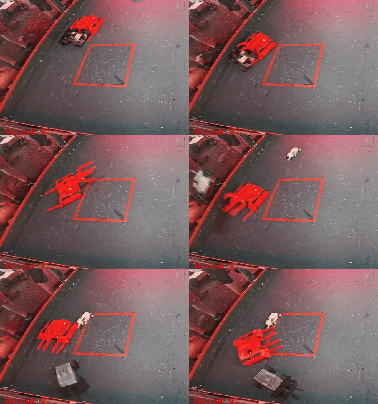
I managed to squeak in one last whiteboard against Babrog, Bob Toss, and Siren. Absolute chaos, great fun. Managed to get a couple of lifts in, pushed some bots around, and ended it all as victim to an absolutely perfect suplex into the pit, RGB twinkling forlornly and “You made me look bad, and that’s not good” for the camera to see. Can I get that as a gif?
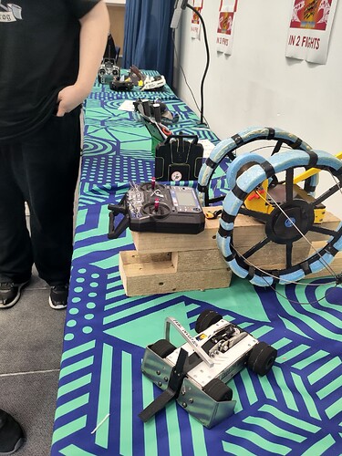
As an aside, I’m also very humbled by all the interest in and positive feedback about the robot that I had on the day, with lots of people taking pictures of it next to their bots on the ready table, and wandering over to my pit table to look inside. I usually build my dumb projects purely for my own entertainment, so it’s great to know other people think my robot is cool too!
Some photos:
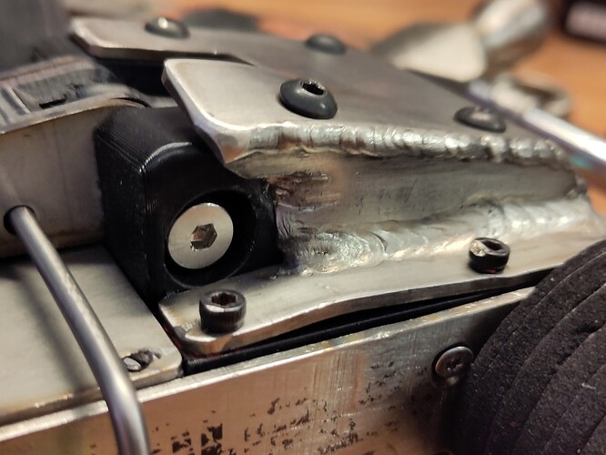
Straight to corner, where three pieces of steel meet (two welded and one brazed on top). I trust my welding a little more now.
Narrowly missing the hardox…
Finally, thanks again to the BBB team for putting on another excellent event! I had a great time, and I had some spectators come and they had a great time too. Sounds like I might have converted a few more folks. Also, big shout out to Eoin for understanding the reference and hopefully introducing a few more audience members to a cinematic gem.
Now, back to CAD. The sooner I don’t finish these upgrades the sooner I can be in a mad panic trying to finish them for the next event.
I feel personally attacked by your past paragraph ![]()
Great write up and glad to hear the bot performed as expected!
Don’t talk to me or my son ever again.
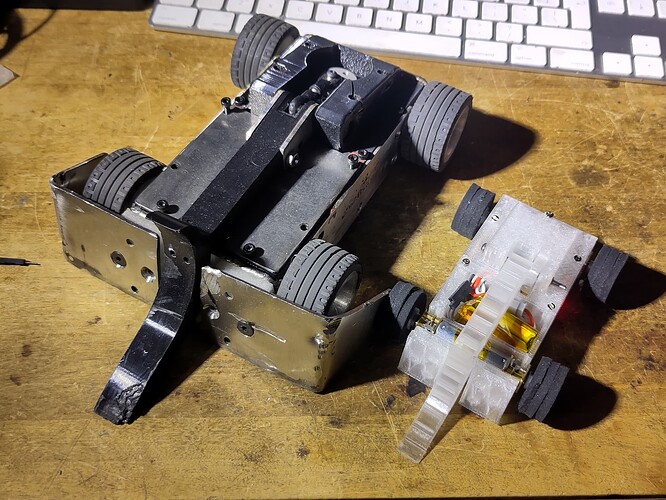
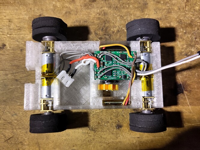
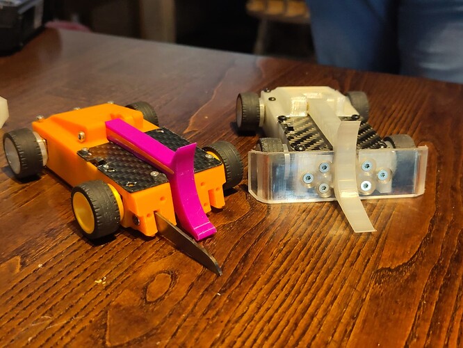
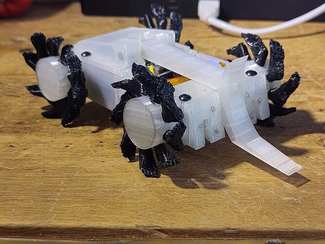
A couple of us at Swindon Makerspace are trying to get some tabletop plastic antweight action going, and name begat robot - meet Fatal Deviant. 60% scale Fatal Deviation with N10 motors and a 9g mini servo. I think there’s enough room inside for me to get weird with a soldering iron and magnet wire. Sneak peak on upgraded internals for the smallest big bot out there if you squint.
Since I’m babysitting a 10hr print for the next iteration of the robot guts it’s time to write some stuff about the updates I teased earlier. I was mostly happy with the performance of the bot at Champs, but the multi-part internal subframe ended up making wiring the bot extremely difficult, and it was a pain to iterate designs with so many different components tied together.
After people sniping my weapon linkage my main issue at champs was gearbox reliability, and I ended up stripping all my tiny bevel gears, so I stepped up from 0.5 to 0.8 module gears. It doesn’t sound like a big difference but the teeth are much bigger, stronger, and resistant to misalignment than the old ones. I designed a new minimalist gearbox housing to suit, currently prototyped in PETG but PCBway will make them in laser sintered stainless steel for £7 each, or aluminium for £6 each. A few years ago I designed and ordered a sintered stainless body for my Casio watch, and I’ve been wearing it daily ever since. If it can survive that it can survive any combat robot.
With the new gearboxes I’ve done away with the stainless steel bulkheads, so now all the components are sandwiched in a three part TPU clamshell. The PCB slots into the bottom and all the wiring sits in channels. Big fan of this design from a serviceability perspective, although I have to figure out how to retain the motors so they don’t fall out every time I turn it upside down…
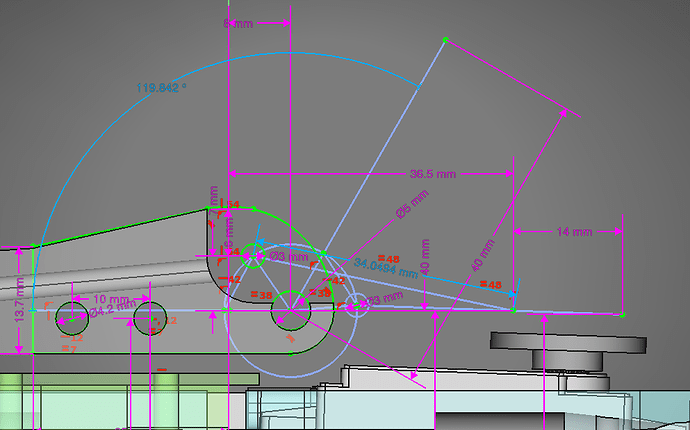
I also did some cursed CAD to figure out how to optimise the weapon linkage for the best combination of leverage and throw. At Champs it could only open to about 90 degrees, but it’s now all the way up to 120. I haven’t properly tested it yet, but it’ll comfortably self right the naked chassis, and it’ll lift my 2.2kg (much abused) roomba clone with ease.
The linkage optimisation and the new TPU clamshell mean that I’ve managed to fully enclose the weapon linkage, which was the reason I lost two fights at champs. While there’s not currently any provision for mounting hardware, I plan to fit some armour over the top of the linkage to fully protect it.
Very confident in this design now. I’m under no delusions about winning anything, but I think it’s durable enough to get knocked around some more and leave me to focus on driving.
Hey, think I got this?
Didn’t get a spot at BBB Brawl, so spent a couple of days on the Swindon Makerspace stand at the Festival of Tomorrow in Swindon instead, with Fatal Deviation on display on our table. The crowd was a bit young to be interested in a robot that didn’t move (if we’re talking static robots the laser cut Wall-E was much more enticing), but a couple of folks were interested and it’s made for some good social media content at the very least!
I have spent the last few months tweaking the bot and the drive tunings, and it’s driving better and better. A pending JLC order for gearbox housings means I’ve hit design freeze, so I’ve spent the order queue time tidying up the CAD and code. As a result, I feel it’s in a state I can post it to github, so if you want to see a fairly concise write-up on how I squeezed beetleweight components into a 1lb footprint, check it out. The github readme also includes some sneak peaks of my new top armour configuration.
Finally, I recently finished engine swapping the blown up engine in my camper van, so now no event in the country is safe from me - due to missing out on the Brawl, I signed up for Robodojo in March instead. With only 12 signups on the roster so far I don’t know what to expect, but it’s an excuse to go fight robots and sleep in the woods so I can’t really go wrong.
New top armour config cut and assembled. I don’t know why, but hand fabricating parts from the CAD model and having them fit the robot is somehow more magical than seeing the 3D printer shit them out perfectly to spec.
If I have time tomorrow I will make a similar setup from some Tepex my flatmate gave me, which is a carbon composite plastic like Tegris but using polycarbonate instead of UHMW. I don’t need the beefy top armour when fighting control bots, so I might as well lose some weight and gain some acceleration and handling.
I also finally tracked down the issue that caused the front right motor to drop out below about 50% battery, which left me spinning in circles during my fight against Cormoran at Champs in October. Turns out I had fitted the wrong tiny off-white SMD capacitor to both of my drive boards, meaning that one drive channel wasn’t correctly generating its own supply voltage and was freaking out about 50% of the time I punched the throttle. Easy mistake to make, hard mistake to spot.
Ready for Robodojo. Not used to the feeling of being ready so early, I usually consider the bot “ready” some time during the event itself… This time I’ve had time to loctite all my metal to metal screws, assemble some spare gearboxes ready to drop into the robot, prep a spare drive PCB, and even purchase more than one battery!
Tonight the builder of Flick visited Swindon Makerspace and informed me that Robodojo events have a reputation for destroying robots, so I guess it’s time to get rekt again.
And get rekt I did. After not quite enough sleep in a layby in the woods next to a high speed train line (oops) I rolled up to the Dojo, got set up and tech checked, and them immediately thrown in the arena with the biggest horizontal spinner there, Chris Griffin 2.
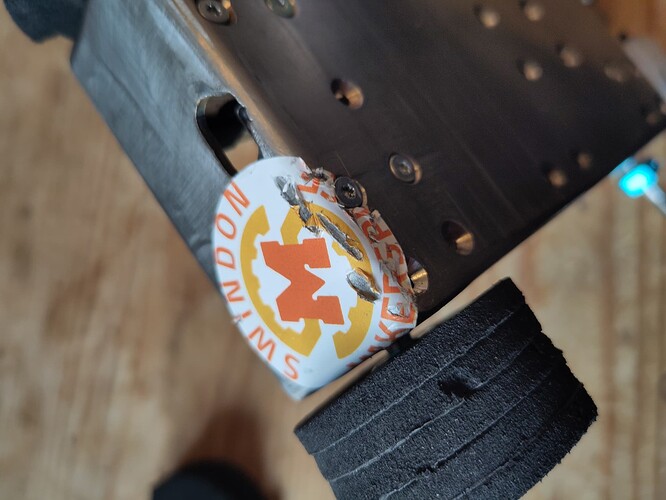
The first thing I realised is that I have zero grip in the Robodojo arena. My big foamy tyres work fine in the BBB arena, with its fresh paint and lack of farm dust, but the Dojo arena meta is apparently “PU tyres and lots of magnets”, neither of which I have. All I could do was my best to keep the front of the robot facing forwards, and somehow I managed to maintain just enough mobility for physics to take over and Chris Griffin 2 to end up OOTA. My first (and, spoilers, only) win of the day. The following photos show the sorry state of my bot as it came out of the arena.
Believe it or not, aside from the armour damage the robot was fully functional. Ten minutes with my biggest lump hammer in a bench vice, two new wheels, and a couple of replacement screws and I was good to go against Bulbaroar. Its builder Martin apologised to me in advance for the typical Robodojo welcome; apparently getting disassembled by Bulbaroar is a rite of passage there.
Another extremely loud few seconds of frantically trying to keep my bot pointing in the right direction, and this time it was me left teetering half way off the edge of the OOTA platform. I did however get a couple of good lifts in this time, and again the bot came out with just a bent wedge and a chewed up wheel. Another few minutes hammering and it’s good to go again.
My third fight was against Agro-Wobba, who had stripped their weapon gearbox earlier in the day. I was excited to not have to bash my robot straight again after this fight, and promised not to flip Agro-Wobba and leave them helpless “unless it looks like I’m losing”. Unfortunately I didn’t get my chance, as I drove straight out of the arena about half way through. At least I didn’t have to fix anything.
Finally I had a chance to play the heel and take out the very impressive newcomer Reisen, sitting at 3-0 and lined up to take 1st place with its enormous eggbeater spinner. Being the last fight of the day I went straight in with a weapon to weapon lift, flipping Reisen over and sending it bouncing around wildly. I then promptly drove straight out of the arena again. Aside from a sizeable chunk machined out of the top of my wedge, again no damage.
All in all, a mixed bag. I enjoyed having a more laid back day to talk robots with the other builders at a new-to-me venue, and will definitely be back. I’m very impressed with the bot - it’s finally showing the durability I wanted from the design, and mechanically it was flawless all day. The lifter geometry (that I definitely didn’t just eyeball) was the perfect shape for weapon to weapon lifts against the eggbeaters without getting particularly chewed up. The drive electronics did exactly what they were supposed to do, and gave me some control where I would otherwise have none. Unfortunately I’m not so jazzed about my driving; the only reason the bot drove straight at all was the electronic stability control, but like any vehicle with too much power and not enough grip it’s no substitute for talent, and I rapidly, repeatedly, and somewhat embarrassingly ran out of skill.
Despite going 1-3 I had a great day, and I think I can do better with magnets, and maybe some PU tyres, and maybe a hardox wedge that I don’t have to bash straight after every fight. Otherwise, I don’t thinkI have any major changes to make. Instead I’m going to focus my efforts on learning to drive, and working on developing another bot that’s a little more destructive and a lot weirder.
Video is up! My fights are at 0:00, 17:45, 21:40 and 35:45. Watching the video back I see my problem, my driving is too Will Bales.
Got there eventually with Fatal Deviant. Signed up for ORCS in May, but I’ve persuaded at least one Makerspace friend to build one of their own, so I’m going to be getting some driving practice in first. They feel remarkably similar to drive, although the IMU isn’t working on the antweight PCB yet.
Also, after The Fast and the Furious: Robodojo Drift I went on a Bricklink spending spree and spent the amazing sum of £8 on 25 lego tyres, pre-chewed. (they’re going through the dishwasher before I play with them). I’ve also reserved some interior space on the bot from day 1 (yes, there’s actually still some left) for magnets, but I’d also like a new wedge and I’m running out of weight. One or the other will probably happen before the May Dojo event.
Speaking of Tokyo Drift, here’s a video of Fatal Deviation playing the theme to Tokyo drift via motor PWM modulation.
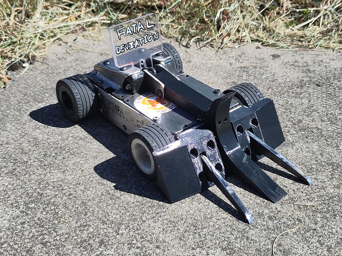
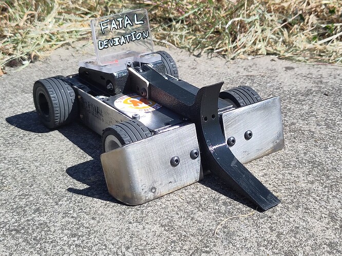
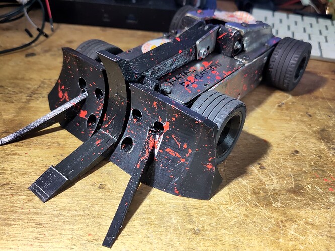
If i say so myself, Fatal Deviation went to Robodojo rd6 looking absolutely stunning, its best drip yet. I had some hardox offcuts in my scrap pile, so I was able to cut myself a set of forks for the new Forkal Deviation front end. I also made a new wedge from 3mm stainless, mostly just to see if I could get, say, a 3mm hardox wedge within weight. Turns out I can, but I’m going to have to cut some weight elsewhere else to run in full medieval knight mode with the top armour too.
There’s even a modest number of magnets hidden in various pockets in the TPU parts of the robot.
Good news, for a change my lineup was mostly control bots. Bad news, it’s Boom Zoom, Chucky, and Shuv-it, and I get to start the day with Sniper.
Event video is here, my fights are at 6:50, 11:35, 23:55, and 28:45.
Sniper took a good few swings at my shiny new wedge and ended up ripping the wedge and its TPU mount off the front of the robot. Considering it was held on by just the heads of seven M4 cap head bolts (no washers even) it was only a matter of time.
I didn’t suffer any damage in the following three control bot fights, but I did get pushed out of the arena backwards by Boom Zoom. A far more honourable (and also very common) way to go versus shooting off backwards under your own power, so I’ll take it.
The fights with Chucky and Shuv-it went very similarly, with me constantly zipping about hunting for a side or a corner, and then missing the crucial “lift” part of the engagement that lifter bots rely on, while in return getting pinned and pushed around a lot. Turns out most control bots are dustpan style when your robot is half their size. Both fights went to the judges, where I lost, but I’m just happy to make it to the judges at this point.
Round 6 was also the final round of the season, and it turns out the 2024/2025 season podium is; Boom Zoom, Sniper, and Shuv-it. Chucky is there too, in 10th place. With a schedule like that I was pretty much guaranteed the 0:4 from the beginning, but this is the first event I’ve felt like I’ve had fights where there’s been some actual back and forth action, so it’s about the best 0:4 I could hope for.
Fatal Deviant also fought for the first time at ORCS8, going 1:4 with a somewhat lucky win against Forky, but then driving off the arena four times again. It also came 3rd in the craziest 23 bot gladiator rumble I’ve ever seen, with sibling bot Scootaloo (same basic chassis design but with more colours, different attachments, and driven by a friend) winning both the off-road warfare side event redemption rumble, and also the gladiator rumble.
I won’t be doing much antposting since this is the small big bot thread, but I will be continuing to fight it specifically as a scaled down Fatal Deviation, where I can test things and practice driving. With the antweight IMUs now working, the two bots run approximately the same stability control/mixing code, so as a result feel pretty similar to drive. It might also feature in the arena as a minibot, because despite being utterly ineffectual towards most beetleweights (it might counter another mini), that’s extremely cute.
I have a spot at the Summer Showdown in July, so I need to think about fixing some stuff, and also maybe some updates and improvements. I’m very happy with the durability; two pretty brutal dojo events have only really resulted in minor damage (wheels/tyres, bent wedges, chunked TPU). I feel the call of the hardox wedge, but not until I find a supplier that can cut and bend it (and also I can budget for it again). Rev2 electronics have been flawless, although that’s always the bit I’ve had the most confidence in. All I’ve done since BBB champs is fix the one I blew up in a reverse polarity incident (4x motor drivers and a vreg later it works) and keep the code updated.
Drive is almost great, but at the last event it was held together with threadlock and a prayer and it deserves a full strip down and rebuild with grease and fresh motors. I actually haven’t killed a single aliexpress gearbox yet either, but I think that will be how I tell when I’ve installed enough magnets. Grip was way better in the dojodust with lego tyres and a little bit of magnet, so I’m hoping a lot of magnet will do the trick there.
The forks worked really well, although they’re too short for real fork on fork action - the antweight version is better in this regard because it’s in the same size range as most of its competitors. I can’t run the metal ones for pub beetles, but that at least means I can experiment with plastic forks of different geometries. Something to note is that if a fork hitches briefly on a crack in the floor, the stability control will do its absolute best to compensate and keep you going where you were initially pointed. I think I said a while back I didn’t want to play the ground game, but maybe tiny robot + too much electronics is the secret to ground game?
Finally, driving. I think I’ve improved, you can tell because I stopped driving (the beetleweight, at least) off the edge of the arena. I’m thinking less about driving the robot and more about the fight, and when I’m driving solo it feels really intuitive - brain ↔ robot link go brrrr. Something I did see while watching the footage back is that I stop driving forwards when trying to flip, allowing my opponent time to slide off the lifter. I gotta stop that. It might be the controller - even with some extra lever glued on I’m having trouble fully gripping the toggle for the lifter channel, but it might just be me not having enough brain cells to do two things at once.
That’s a pretty solid wall of text, and I should go to bed. Here’s a picture of Feetal Deviant to haunt your dreams.
New look for pub beetles! I’m hoping this new TPU wedge can stay attached most of the time, and I just add and remove forks when required. No real changes since the last dojo otherwise - just some tweaks to the internal clamshell parts for better stiffness and easier printing.
Pub beetles was another 0:3, but I still had a blast bouncing around the arena and playing in the ball pit. When the bot drove well it drove really well, unfortunately since switching from foamies to lego tyres the aliexpress gearboxes have been letting me down, and I killed more than a few in the arena (despite absolutely ramming them with grease then limiting the motor current and slew rate to try preserve them). The good news is since speccing them I now have enough internal space for something a little more suitable - maybe the kind folks at BBB would consider selling naked gearboxes for me to put my spicy motors in? ![]()
Since last year’s pub beetles was Fatal Deviation’s first outing it feels a little significant, and I’m pleased to see how far it’s come in a year and a bit (and five events). As a bit of a retrospective:
- The design has changed a lot, but the core concept is about where I wanted it to be. Despite its size it’s really easy to work on (I just have to cope with needing tweezers to work on it sometimes), and I can slide the guts out and access any part in a couple of minutes.
- I’ve gleefully sent it face first into some of the biggest hitters in the sport again and again and it’s come out the other side with a handful of shredded tyres, a couple of bent wedges and a snapped weapon linkage or two. I would really like to see someone try peel it open though!
- The fully independent 4WD works pretty well and has allowed me to play with all kinds of weird control mixing algorithms. Most of them don’t work any better than a basic tank mix, but it’s fun to experiment with, and with stronger gearboxes I’ll be able to try more extreme things (like reversing an inside wheel to turn faster).
- I’m totally sold on the IMU integration. Since the angle of the wheel on the controller is mapped to the target angular velocity of the robot, it doesn’t take long for it to become totally intuitive. I handed the controller to a friend who’d never driven a combat robot before, and immediately they were doing controlled drifts through doorways and around the cat. In the arena it’ll compensate for a dodgy motor/gearbox, or the forks hanging up on seams, or a punt from a passing robot. It feels very planted in a way I can’t quite explain.
- It’s very hard to drive a small control bot. Even with similar power and traction to other bots I find myself dustpanned by bots that don’t usually dustpan. I’ve been doing a better job at getting to the back and sides of opponents, but it’s hard to catch them on the lifter. I think I have to embrace the smol and try to get totally underneath other robots.
- It needs more RGB. It needs Need for Speed, Fast and the Furious style underglow. Right now it’s actually thermally limited by the linear regulator on the PCB, so I guess I need to do another PCB revision specifically for more RGB.
Overall, very happy. With more robust gearboxes I should just be able to charge the battery and throw it in the arena, leaving me time to focus on building other, dumber things.
Also, while I’m here, is there any interest in me doing a breakdown on how the electronics and code work? It’s not really something I’ve explained in much detail yet, but I also know what I’ve done is pretty unusual so maybe people are keen? Please let me know!
Buckle up those ESD wrist straps and comb the crumbs out of your neckbeards*, it’s hardware time. Some background before I go deep! I have a degree in electronic and electronic engineering, and a decade or so experience in industry, most recently designing weird in house test equipment for a consumer electronics company. I have designed so many PCBs I sometimes see KiCAD when I close my eyes, and sometimes (rarely) my boards even works on revision 1. All that is to say, there’s absolutely zero way I was building a combat robot and not going the extra mile and putting my own electronics in there! This post is half explaining my design choices, half explaining how I go through the process of designing a board.
*I’m only allowed to say this because I haven’t trimmed my beard in weeks, and I’m starting to look like someone who lives in a cave in the Appalachian mountains and only drinks moonshine and eats raw deer meat.
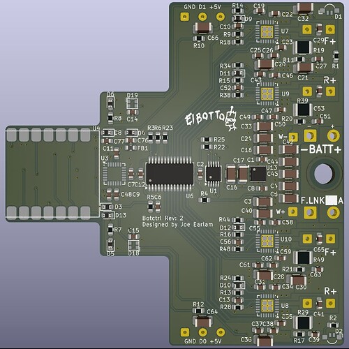
This board handles everything electronic inside Fatal Deviation that’s not inside the receiver or the weapon servo. It takes the channel data from the ibus receiver, combines it with the data from the IMU, and calculates how much power each motor requires to go in the direction you’ve asked it to. It also provides power and signal to the weapon servo, and of course RGB underglow.
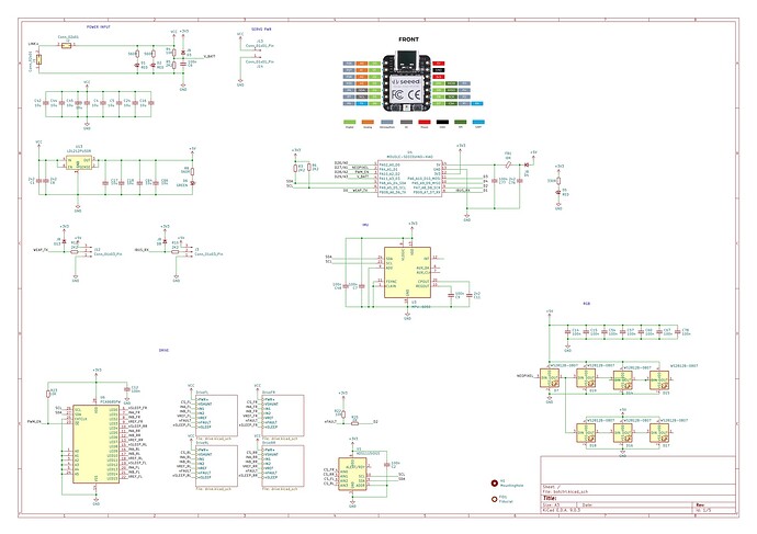
This is the top level schematic. It’s arranged into sections - power top left, drive bottom left etc - if you zoom in they’re labelled. The main parts are:
- Seeed Xiao RP2040 microcontroller
- 4x TI DRV8526 brushed motor controllers
- PCA9685 I2C PWM controller/IO expander
- MPU-6050 IMU
- ADS-1115 ADC
- 7x WS2812B (aka Neopixels) in tiny 0807 SMD format
Most of the parts were chosen purely due to my familiarity with them from previous projects. The only exception was the DRV8526 motor drivers. I was aiming for approximately 6A of drive current per channel, as while the Valkyrie motors have a 14A stall current rating, a heavily loaded wheel on a bench top power supply might only draw 4-5A maximum, and ~500mA unloaded. Keeping stall current regulated to just a little above normal operating current means the driver can detect stalls and kill power before the brushes and windings cook themselves. In this application there’s no benefit to running the full stall current - drive wheels usually spin way before they lock up, and ifthey’re truly locked up (jammed against a wall or in a grabber) you don’t want to give them full power. Stall current is, however, something you’d 100% be thinking about for a lifter/grabber motor.
The PCA9685 PWM driver was used because the Seeed Xiao board doesn’t have enough GPIO pins to control all the motor driver functionality. A future revision of the board might eliminate it by switching to a bare RP2040 (which has enough pins, more than the Seeed form factor can handle), but the ease of soldering on a £2.50 dev board wins out for now.
When I draw a schematic I usually start with the power section. In this case there’s not much going on. Some pads to connect to the battery loom (and fuse). Some pads for a link that I ended up not using. Some indicator LEDs, bulk capacitance, and a 5V linear regulator to power the Xiao and RGB underglow. There’s also a voltage divider for battery voltage, with a filtering cap and a diode to 3V3. The diode is a belt and braces clamping diode that stops the voltage on that line from exceeding 3.3V plus the forward voltage of the diode. It shouldn’t, but sometimes weird stuff happens.
Clockwise it’s the MCU, IMU, and RGB. Nothing much going on here either - I just copied the application schematic for the IMU. The MCU has basically everything it needs onboard already, but I added some extra capacitance and a series diode. There’s also a ferrite bead specced, but I’ve been fitting a 0 ohm resistor instead without issue. The series diode prevents the rest of the board from being powered while programming, and also prevents the USB 5V rail arguing with the 5V linear regulator over who’s boss. Speaking of linear regulators, the RGB on this board is actually thermally limited to about 50% brightness by the temperature of the linear regulator, which is disappointing.
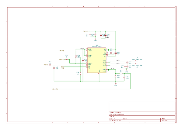
The motor driver sections of the schematic are enclosed in hierarchical sheets - this is because it’s just the same section copy and pasted four times, and using a sheet allows you to use the same schematic as a reference for multiple blocks. In this instance it’s essentially the datasheet application schematic (always a good start when designing something!), with the addition of some high frequency decoupling capacitors on the motor pins (C41,69,73), a diode on the fault pin, and a low pass filter on the current shunt.
The full set of decoupling caps are pretty extra, usually you can get by with just a ceramic cap across the motor terminals on the can, and/or fitting just C41 while omitting C69 and C71, but seeing that Fatal Deviation is a radio controlled steel box with no room for a receiver antenna I wanted to minimise EMI where possible.
The diode’s part number is “JB”, standing for “jellybean”. I didn’t have enough MCU pins to be able to connect all the fault pins their own inputs, so I OR them together with diodes and use it to check overall drive status instead of individual axles. I haven’t actually used this feature yet, I’m happy just having faults reset themselves automatically. If you ever see me limp the robot to the opposite side of the arena and pause for 1-2 seconds before resuming, I’m waiting for the 1s reset timeout to see if it fixes anything!
The LPF on the current shunt allows me to ignore the effect of the motor PWM frequency on the current readings. Without the LPF the ADC will either read full, short circuit winding current (when the PWM cycle is on), or no current (when the PWM cycle is off). While there’s benefits to taking a tonne of samples throught the PWM cycle and doing the filtering in software, in circumstances like this an analogue filter works just fine to smooth the pulses out to an average level. I read the current shunt voltages directly with an ADC1115, which has internal amplifiers with up to 32x gain, meaning I don’t need any external circuitry to measure the 0-60 millivolts or so across the shunts.
So far, everything is pretty standard, straight out of the datasheet stuff. It probably took me 5-10 hours to design the schematic, including part selection and a little bit of Spreadsheet Time for calculating component values and such. The PCB, on the other hand, probably has 40 hours behind it. Laying out and routing PCBs (especially >2 layers) is like piloting the Windows 95 Pipes screensaver and I find it extremely meditative, very easy to get lost in. I figure if I’m going to spend the time it might as well make it count, so I spend a lot of time shuffling things around to prioritise things like symmetry, aligning and spacing of components and traces, and using the absolute lowest number of vias possible.
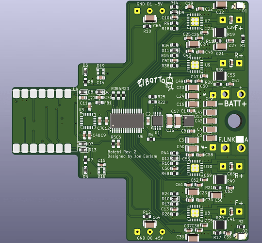
The first step to laying out a PCB is usually the mechanical layer; either defining the space the board has to fit into, or roughly defining the board size required to fit the design into (depending on how critical form factor is). For such a tightly integrated design as FD there’s an amount of chicken and egg involved; exporting the board shape as a STEP file into freeCAD, then shuffling the board around in space while also changing its dimensions, until finally it fits into the space left inside the robot. I settled on the shape above, which is almost the full width of the robot interior, and half the length, except for cutouts for gearbox clearance.
Once the overall dimensions are specified it’s best to figure out rough locations for things like connectors and any components with mechanical constraints or requirements. In this case it meant placing the MCU (with its exposed USB-C connector) and some power and signal pads. I also placed a single M4 screw hole to soft-mount the PCB into the TPU guts of the robot with an M3 screw. It’s otherwise retained by just pressure and EPDM foam, allowing the board and robot to flex and shift independently of each other.
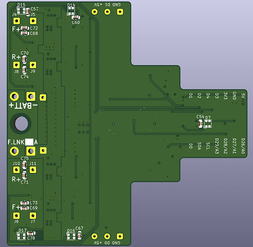
The board uses a four layer stackup. From top to bottom these are loosely assigned as signal, GND, PWR, signal. Aside from the power plane, which has a 5V zone fill, all the layers use a ground zone fill by default. The second layer’s ground plane is left uninterrupted* across the whole board. Putting the power and ground fills on the internal layers (which are physically closer together) gives you some free capacitance for high frequency decoupling. Exposing big external board-wide power fills to the outside world is also generally a bad idea, especially inside a metal robot, as it massively increases the chances of a short.
*Mostly, we’ll get to that.
The next step is to define the “most critical” portions of the circuit to lay out first, so that less important things can be laid out around it. The focus here is to get power from the battery and out to the motors as efficiently as possible, so it makes sense to put the motor drivers down first, and do it close to the power input. For this section I used a kicad plugin for generating PCB layouts for hierarchical sheets, so you only have to lay it out the one time. Thankfully I was able to fit all four drivers perfectly along the required edge.
Supplying power to the motor driver ICs takes some work. According to the kicad trace width calculator, to carry 6A down a 50mm trace with 20 degrees of permissible temperature rise requires a 2.3mm wide trace. 12A requires 6mm! You can reduce these by half by choosing 70um thickness copper (default is usually 35), but; the widest trace we can get into a pad on the tiny SMD motor drivers is still only 0.25mm, and choosing thicker copper is usually expensive, especially on >2 layer boards. The solution is (again) zones. It’s easiest to see from the bottom face of the board, where battery + enters the board, passes through the unused link pads (bridged with a wire on these boards), and into a large zone that spans the full width of the board. This exists in some form on every layer, and provides a large, low resistance, low inductance connection for the motor drivers. Now each 0.25mm wide power pad has a small area of decoupled (at least 10uf and 100n per power pin) copper zone, each connected to the contiguous zones below with lots of via stitching. Vias have high inductance, so using a decent number to tie zones together is a good idea.
The area on the top side of the board between the motor drivers contains the board’s bulk capacitance, which means I simply placed as many 1206 10uf capacitors as I could fit in the space available. When board space is constrained, spending the time to work out a tidy low inductance design can make more difference than trying to squeeze in more capacitors in less than optimal places. Also, I don’t have the Z height for larger capacitors, and I found this reel of 1206 10uf caps in a bin, so I might as well use them up. I haven’t seen any issues with voltage sag, a full power launch only causes a few hundred millivolts of battery/wiring/fuse/connector voltage drop.
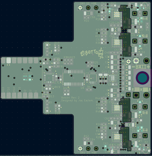
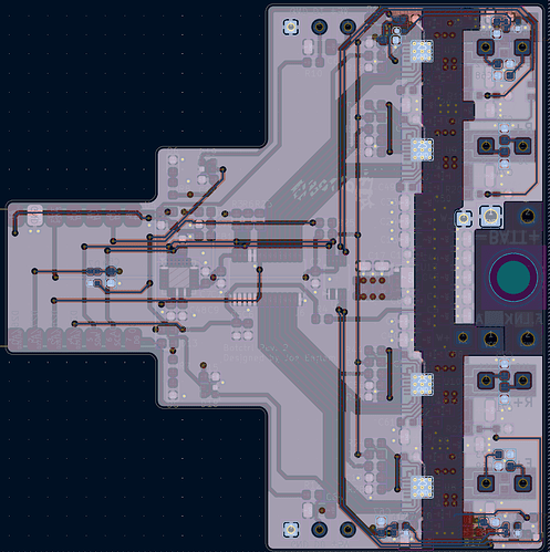
Inner ground layer only, ground plane highlighted.
All layers except inner ground layer, ground plane highlighted.
Remember what I said about the uninterrupted ground plane? I lied, there’s actually some motor driver power zones on that layer too. These zones break up the big continuous ground plane, so that there’s a clearly defined “big power” side and a clearly defined “idk MCU stuff” side. The only place they meet is under the linear regulator and ADC - this keeps the return currents in check, because we don’t want the power that returns to battery ground from the motor drivers to cause issues with the sensitive side of the circuit.
Return currents from the drivers need to be considered as much as the supply currents. A big chunky power feed is great, but if the power has to return to ground through a tiny sliver of copper and zig zag around components it can cause differences in ground potential across different parts of the ground plane. This can manifest anywhere from weird noise on measurements to (in extreme cases) burning up narrow sections of ground plane. We always want to provide enough copper for the current to get back to ground, and (like I’ve tried to do here) it’s sometimes helpful to use physical cutouts in ground planes to isolate these fluctuations away from sensitive ADCs and IMUs to places they won’t matter, like underneath the motor drivers. This is a variation on “star grounding”, which is also good practice for wiring your robot that uses normal robot parts!
With the power sections laid out, everything else goes around them. I was pleased that I could get the IMU, PWM driver, ADC and linear regulator all down the centre line of the board to keep it as symmetrical as possible. RGB and some decoupling capacitors went on the back.
All this time, I haven’t been routing (drawing traces). Once you start routing traces, moving and modifying the design gets a lot harder, so I’ve been dragging components around trying to optimise the rats-nest of connections that should be connected, and only when I’m sure the board is close to final I will start drawing. I have been known to get half way through and scrap the design so that I can start again and do it better.
Once the board is routed, I rubber-duck debug it. I go through the schematic and the datasheet and double check everything I’ve laid down is doing what it’s supposed to. I’ll run the design rule checker to check I’ve not done anything really dumb. Once I’m sure I’ve checked myself I send the files off to one of the big fab houses in China for them to work their magic and wait a few weeks. This is usually about when you start finding bugs.
If I remembered to buy a stencil with the boards, assembly is a case of smearing solder paste through the stencil onto the board, dropping the components on one by one with tweezers, and putting it on a hotplate to reflow the paste. I usually have to clean up some joints with an iron and flux afterwards, but that leaves me with a complete board ready to be programmed and go into the robot.
I think that covers most of the design of this board. Fundamentally a microcontroller with four brushed motor drivers and some sensors and comms isn’t too off the wall, but getting it all to fit inside a tiny robot and not immediately catch fire takes some thought! I’m going to leave it there - stay tuned and keep your pocket protectors ready for the next episode, where I go into the firmware architecture.
Edit: bonus GIF of Fatal Deviation returning to its home planet (it was needed), credit to JoeB
