Fig Roll - a 1.5kg Spring Flipper

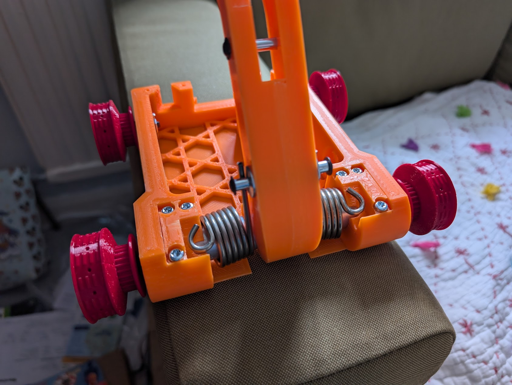
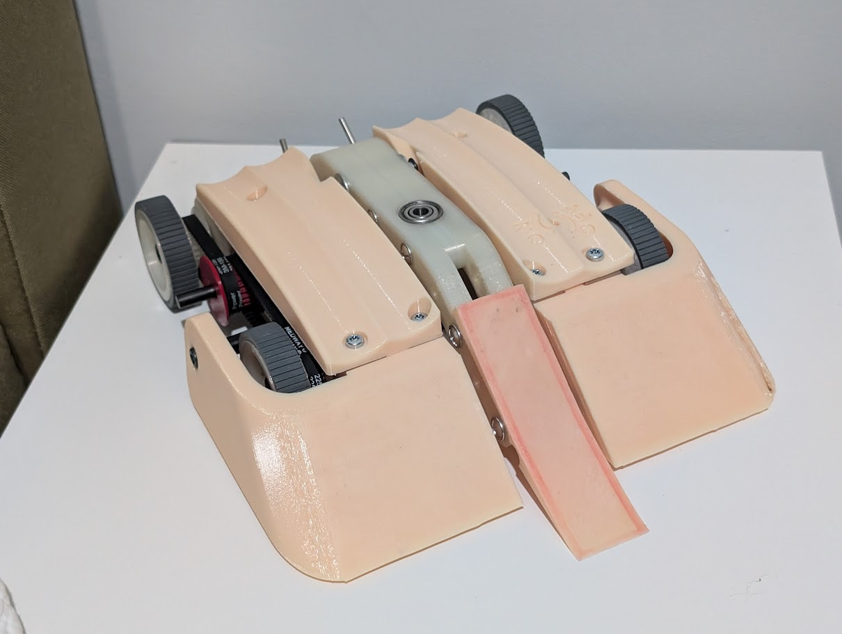
Fig Roll 1 - before it’s first competition.

The Idea

I’d been running Digestive, my 4WD hub motor vertical spinner, since Rapture 2022 and after a disastrous first showing for Digestive 2 at Rapture 2025 I wanted to try a more interesting bot. Digestive was designed to be a simple, boring (hence the name) 4WD vert that was competitive. It was not, despite winning a most destructive award one year, it never made it through the round of 16. Certainly not the top 4 results I was hoping for. I figured that rather than get too frustrated I should focus on what interests me most about robots, making weird overly complicated ones!

Ever since first watching Chaos 2 on RW I’ve loved the idea of flippers and using my opponents weight against them. Modern robots can handle the high shocks of hitting the floor from height so it’s not as effective a weapon as it used to be. However throwing your opponent in the air is the best spectacle in this sport, and flippers are good at that! Unfortunately a full pressure CO2 system is too heavy and very rare at the beetleweight scale.

The Inspiration

Dead Air, a US 16oz combat robot, uses a spring and a motor-driven cam to load and release a spring which it then uses to flip opponents. I loved that idea and wanted to scale it up and adjust it for a UK 1.5kg beetleweight. In preparation for this I ended up buying a pair of torsion springs back in 2013. They sat unused for many years because I got distracted with other designs. But with Digestive 2’s rapid and painful exit from the competition at Rapture 2025 I got inspired by Flick 2.

Josh’s Flick 2 is a very nice spring flipper using 6 tension springs and a servo driven choo-choo mechanism. Now I’d been interested in choo-choos since Tantrum debuted with one at BattleBots but I found that they had a very short ‘throw’ distance compared to their operating diameter. A long time ago I remembered watching a video of a FIRST Tech Challenge team explaining their catapult system. They had a spring loaded catapult arm being pulled down by a string winding around a pulley. However the pulley had a wedge cut out of it so that after a number of turns the string would slip off the pulley pulling the rest of the string off the pulley. This would then release the catapult arm, launching a ball across the arena. Unfortunately I can’t find any evidence of the video at all.

This is your typical choo-choo mechanism:

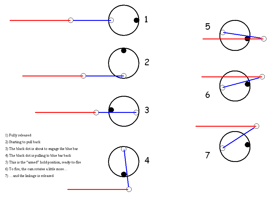
The difference in the position of the red line at position 1 (fully released) and position 5 (armed) is the distance the flipper arm would get pulled down in my spring flipper. However in order to operate I need to have enough clearance for position 4 and the position between 7 and 1 where the blue line is vertical. That’s a lot of room required for a given pull down. The string & modified pulley just needs the pulley diameter plus a bit of clearance. Much more compact.

The Mechanism

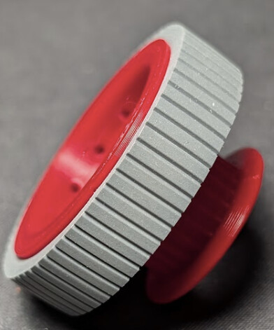
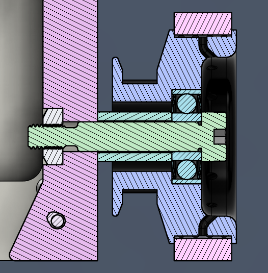
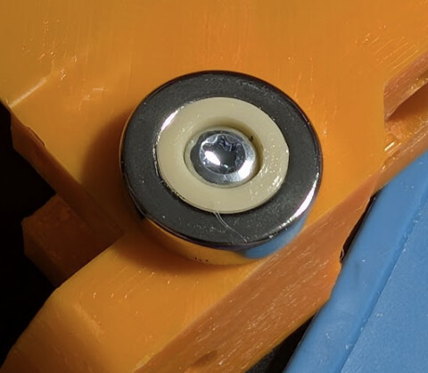
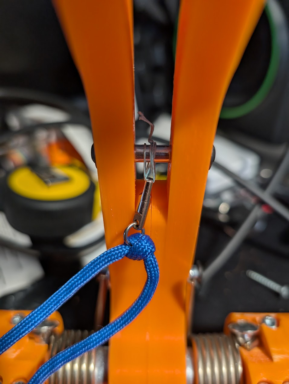
The core of this design is the helix transition. Unlike a standard pulley that has flanges on each end to contain the string, this pulley features a ramp at the end of the winding area.

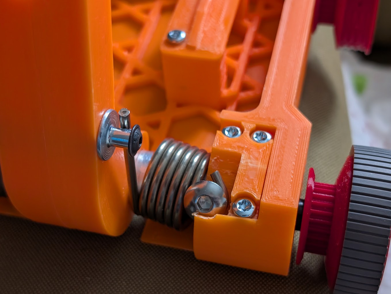
  1. As the motor turns, the cord wraps around the pulley, pulling the spring loaded lever arm down.
  2. Once the string reaches the end of the flat winding surface, it hits the ramp. The lateral force from the angled surface overcomes the friction holding the string in place.
  3. Because the string is under tension, the first loop slipping off creates a “slack wave” that destabilises the friction of the remaining loops. The entire stack collapses and “kicks off” the pulley in rapid succession.

This mechanism has some great advantages:

  • A single wrap around the pulley is the pulley diameter * π so a 30mm diameter pulley can wind up ~95mm of cord per turn.
  • Multiple wraps will still get pulled off e.g. 3 wraps of a 30mm drum is ~283mm of cord which is way more ‘throw’ than an equivalent choo choo mechanism, let alone a snail cam.
  • As the pulley is a constant diameter which makes it easier for the motor to pull down the lever arm as you near the end.

Of course it’s not all brilliant:

  • Every time a loop of the string slips off the pulley it adds a twist to the string. If these aren’t taken out of the system the string’s effective length gets shorter which will jam the mechanism.
  • If the robot suffers a large shock from a spinner hit then it’s possible the string will jump off the pulley prematurely.
  • You need to be reasonably accurate with the length of the cord and the placement of the slope otherwise it will either fire early or it’ll jam.

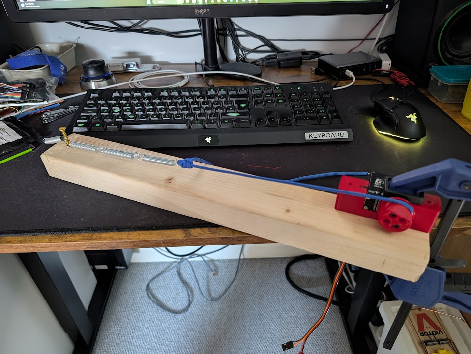
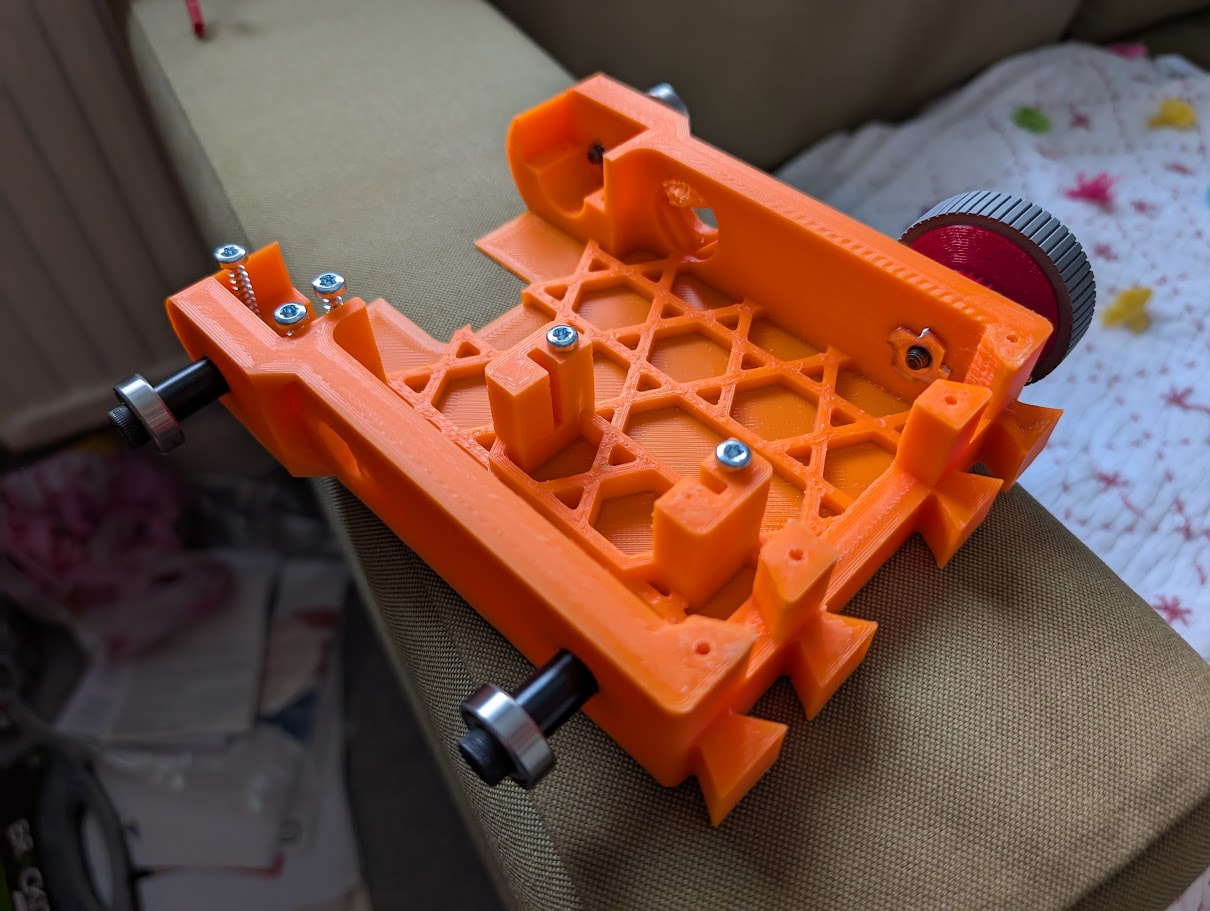
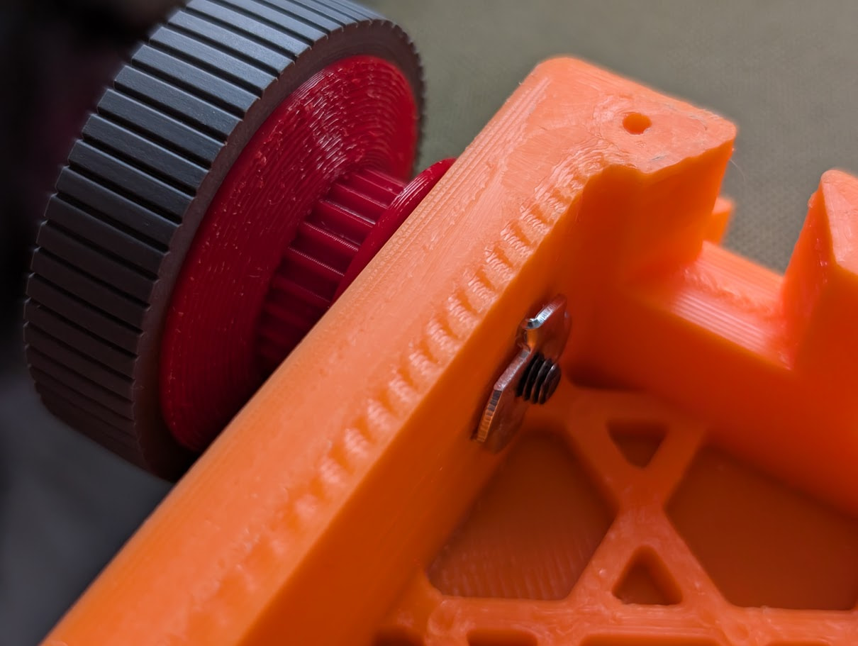
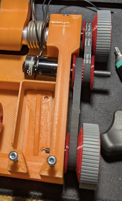
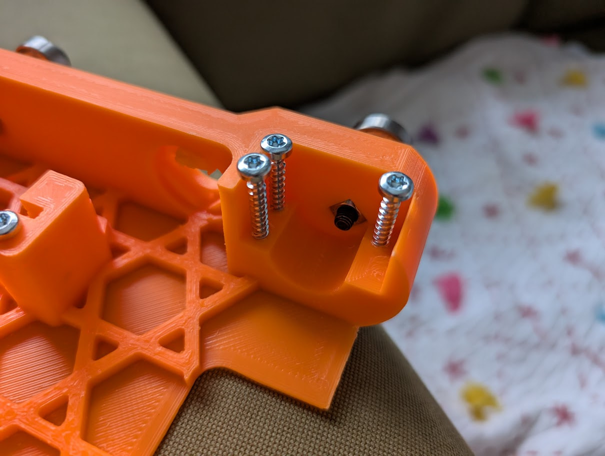
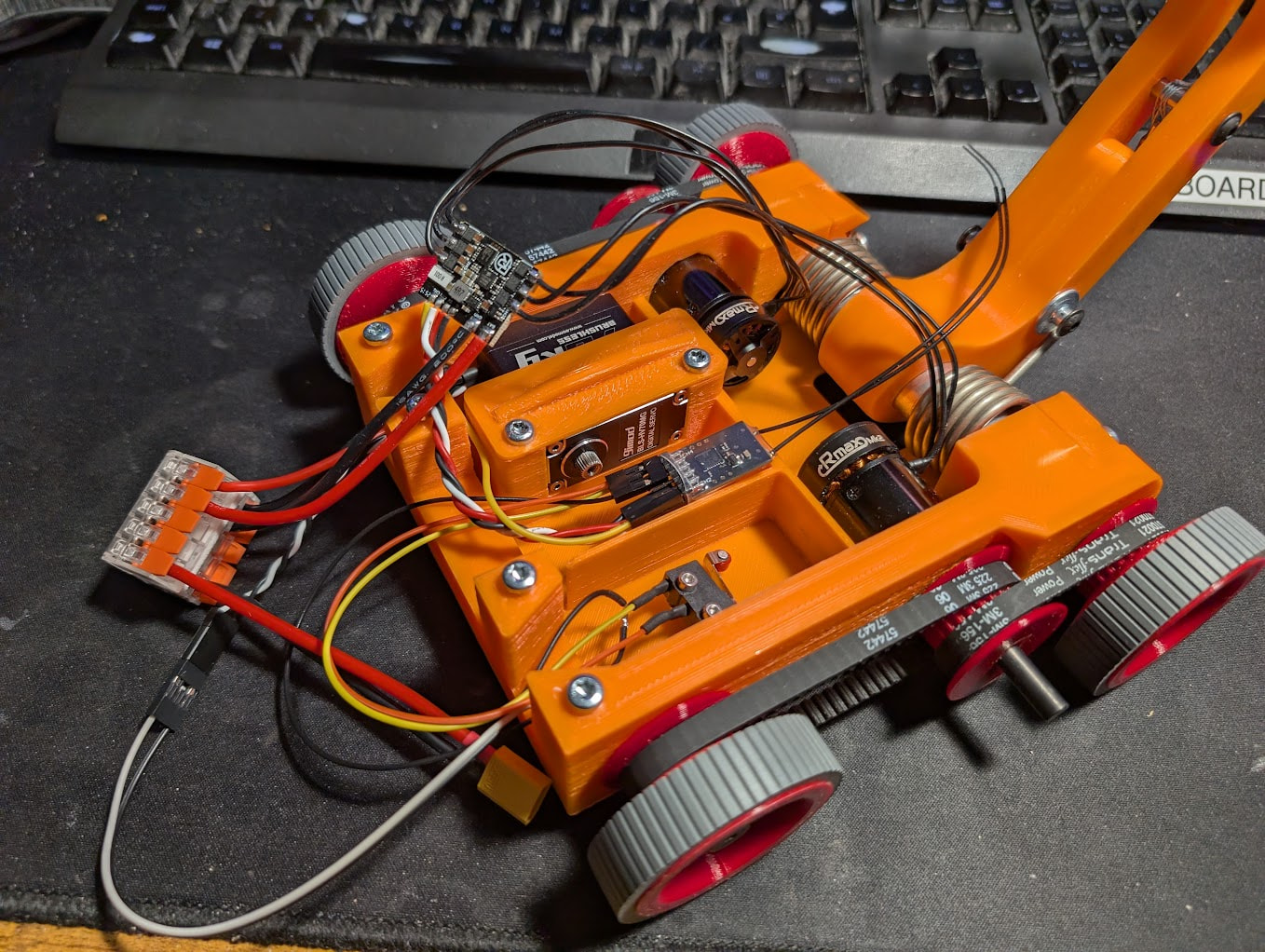
Here’s the early test jig; I’ve got some cheap light tension springs pulling some paracord tight on a pulley that’s mounted to a 9imod 70KG servo. And a video of it releasing:

4 Likes

The Build

One big driver for this robot was wanting to use up a reel of Taulman Bridge 910 nylon that had I bought ages ago and was 2.85mm dia so would only work in my older Ultimaker 2+. It was expensive and fancy so I don’t want to just waste it either by not using it until it expires or just to print silly little widgets with it. It was also the only reason I hadn’t just replaced my Ultimaker 2+ with a Bambu H2D.

Components

For the electronics I was planning on using the Repeat Robotics AM32 Dual ESC again as it had worked really well in Digestive 1 and 2. It’s a very nice ESC in a compact form factor and AM32 lets you configure it easily. The drive motors were a little more tricky. I’d used Repeat Robotics Max v1s in Digestive 1 and didn’t like how the gearbox screws backed out and were impossible to loctite. In Digestive 2 I’d used a pair of Ranglebox MARS gearboxes however one side had locked up sometime in the 2 fights it had and I wasn’t particularly happy with them. After asking around the OOTA discord and the Beetleweight Facebook group chat I went with some Repeat Robotics Max v2s.

However to avoid any problems I decided to decouple the motors from the drive wheels. I wanted to have 4WD, which is turning into a consistent theme with my bots. So each motor would drive a HTD 3M pulley with belts driving the front and back wheels. This arrangement was popular with most high level robots so I figured I may as well copy it!

As I bought the Ranglebox MARS gearboxes for Digestive 2 I also bought a set of the MARS tyres because I wanted to try moving away from my automotive silicon hose tyres. These were very easy to design a hub with an integrated HTD 3M pulley and 626ZZ bearing. Here’s the 2nd prototype in red PLA:

In my testing videos above I was using a 9imod 70KG servo. This was another component I’d bought years before and while it was a high torque gearbox in a compact package it had a small flaw. It was a 270° servo, and I really needed a continuous rotation servo. I didn’t need precision position control, just the high torque and small size. I bought this servo because it was originally quite popular but since I’d bought it people had found it had an issue with high torques stripping gear teeth. But I’m well under it’s max torque rating so it’ll be fine I thought. #foreshadowing

To convert the servo from 270° to continuous I removed the servo’s back cover and removed the original logic board. It was just soldered to the 3 motor pins and tucked the encoder cable I unplugged inside the case. I used a Repeat AM32 35A Drive ESC](Repeat Single AM32 35A Brushless Drive ESC - BBB Shop)again) because it’d be easy to configure and initially thought I could fit it under the original cover, unfortunately it was a little too tall so I had to leave the cover off.

The receiver would be the RadioMaster R84. I love this receiver and have used it in Digestive 1 and 2 successfully. It’s compact and has 4 channels which is exactly what I need for this robot. Channels 1 and 2 will be drive, and I will re-pin the Repeat Dual AM32 ESC so it connects with a 2x3 connector. I’ll use channels 3 and 4 for weapon using a system that Josh told me about, ch3 is the arming channel and will always drive the servo to wind down the string. Channel 4 is the firing channel, it’ll be set at 0% (or really low to keep tension) and then when I press a button on my TX it’ll go to 100% so the servo rotates causing the string to try to wrap around the slope. And if you’ve read part 1 of this thread you’ll know that once the string hits the slope it’ll slip off the pulley firing the flipper.

I just grabbed the battery from Digestive 1 and 2, a GNB 660mAh 4S 90C LiHV Battery. Honestly, with hindsight, it was too large. Because I don’t need to power a large spinner I could really get away with something a lot smaller however it was to hand, and it fit so in it went.

2 Likes

When designing robots I like to 3D print lots of prototypes. I find it really helps me to have something physical in front of me. To see how well things fit together, how easy it is to work on and something I can make quick modifications to to try new ideas. During the 2020 COVID lockdowns a friend had given me about 10 reels of cheap bright orange ABS so I used these in my Ultimaker 2+ to print chassis for testing.

I really liked the idea of [quarter iso-grid](http://www.sheldrake.net/quarter_isogrid/) so tried to use it to stiffen the chassis floor, only to realise it was completely unnecessary and didn’t help at all.

My axle design is easy to see here, an 6mm shoulder bolt with a 626zz bearing and a nylon spacer bolted tightly into a pronged T nut embedded in the 3D print. I’d also been wanting to use pronged T nuts in 3D prints for a while because I thought they’d add a securely fastened threaded hole in a much more robust way than just a nut in a pocket. Unfortunately in this chassis they’re really awkward to press in so I abandoned them and went back to M5 square nuts in pockets.

The choice to use pronged T nuts drove the initial thickness of the side walls, 11mm to fully seat the nuts. However it also worked to make the chassis nice and stiff for the reaction forces from the flipper. The above image also shows the issue with the pronged T nuts, it was hard to drive them completely home as the prongs have a bend that is hard to model. As a result I moved to M5 sqaure nuts rotated 45° to avoid overhangs. Once they’re fitted in place I poke the plastic around them with a soldering iron to create a little smear of plastic to hold the nut in place.

This is the complete wheel assembly which I use for all 4 wheels. The bearing is a tight fit in the 3D printed wheel hub and the whole setup is arranged so the wheel can’t just slip off under heavy loads. Also by having the shoulder bolt be tightly fastened I get a nice rigid connection.

To increase traction I have 4 of these 20mm dia 5mm thick with a 6mm c/s N42 magnets with a claimed 7.1kg pull force magnets under the robot, they’re spaced ~3.5mm from the floor. These 4 magnets ought to give me a total downforce of around 5-6kg in addition to the 1.5kg of robot weight. As a flipper is inherently a control bot I wanted to make sure I could push anyone around.

This is a later iteration of the chassis design, but you can clearly see how the drive motors couple to the front and back wheels via HTD 3M belts.

The springs sit on top of a 19mm OD 1.2mm thick aluminium tube. This is securely clamped at both sides into the chassis, this strengthens the chassis as well as providing a pivot for the flipper.

The spring bolts to the tube with some stainless motorcycle fairing bolts aka shoulder bolts. There’s a M5 square nut inside the tube that seems to work just being jammed into place. The torsion spring’s leg is then fed under a bolt in the flipper arm. The tube is secured with a 3d printed block of plastic that is clamped tight into the chassis with 3x plastite screws on each side.

Here’s an early chassis with most of the bits stuffed into it:

I tried using the swivels you some times find with fishing gear to deal with the twist of the string everytime a loop slipped off the pulley

However they added too much dead weight so eventually I embedded a 626zz bearing in the flipper arm

And here’s a testing video showing it kinda working.

8 Likes