I’ve decided to build a beetleweight. I’ve done some electronics work before, and a little soldering. Aside from that, I’m a complete and utter novice that’s watched too much Robot Wars.
I figured it might be interesting to log the journey of a first robot attempt, to see just how hard it can be!
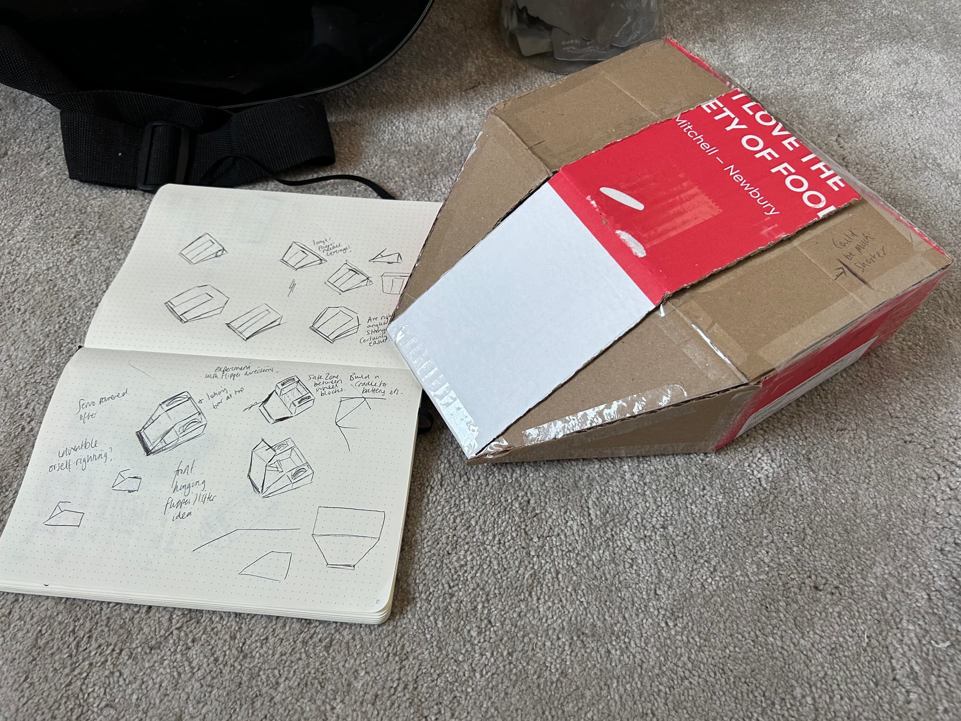
Step 1 was churning out some designs and wasting a load of cardboard. After a spot of advice here I was set on looking into some form of lifter design. That prompted some furious scribbling and led to a cardboard design I didn’t hate:
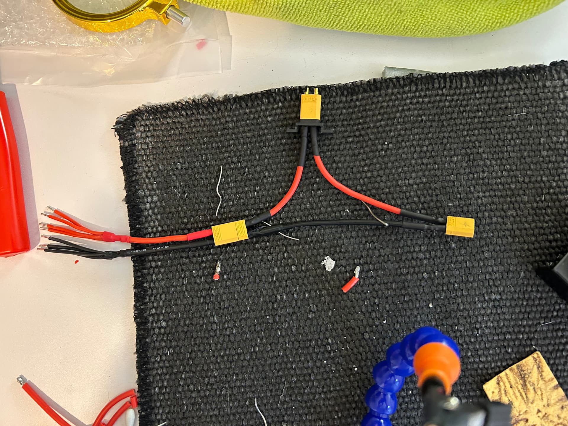
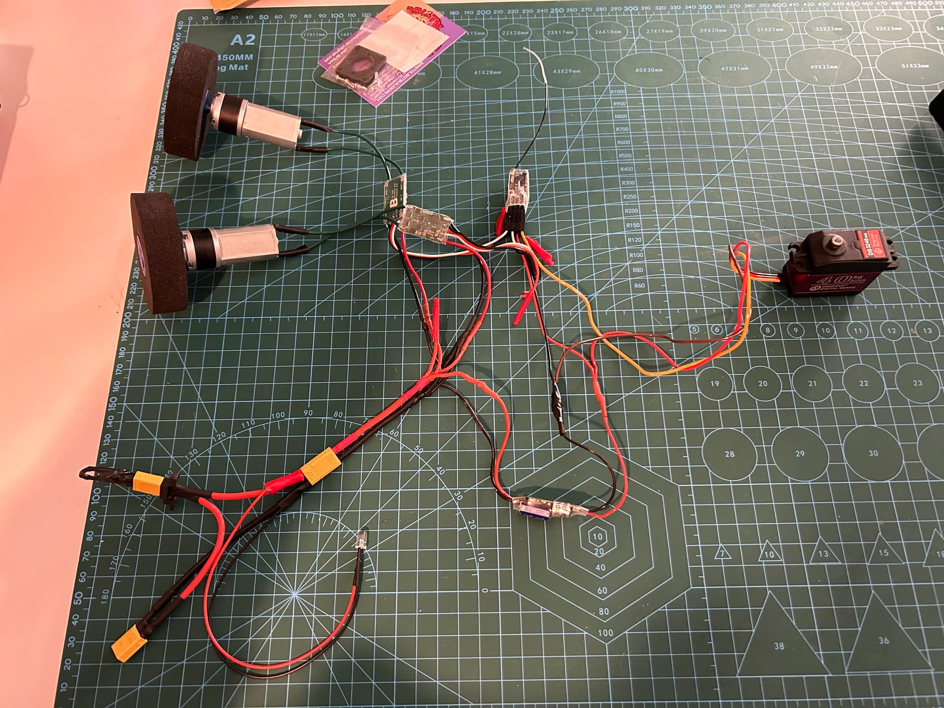
Now I’ve got the beginnings of the safety circuit, I’ll be getting the remainder ready in the next week or so. The plan is to then bundle all of this into the cardboard design and see how far off I was on measurements. Hopefully everything actually works and it’ll move…
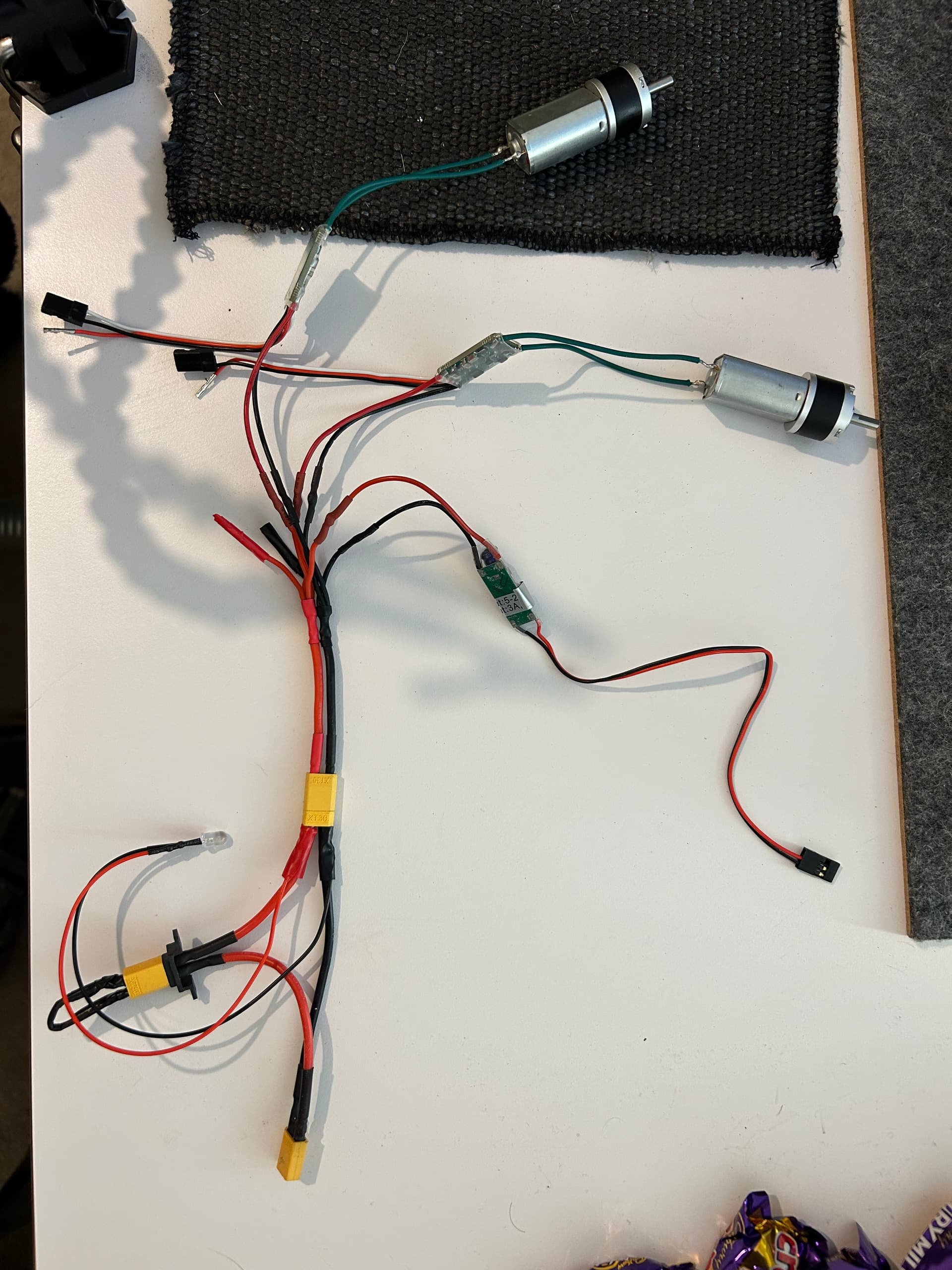
Another update! I’ve joined my local Hackspace (shoutout to Manchester Hackspace) and been down there using their far superior soldering gear. Shy of some insulation tape round the motor connections, we’re ready to get the receiver hooked up and try spinning some wheels!
Question while I’m here actually - on the radio receiver (I’m using the little 4 channel one Here) - should I be soldering the pins onto that? Looks fiddly… it’s either that or hope the heat shrink keeps them in place.
Yes it will be a solder job I’m afraid but it’s incredibly straightforward, though it may look daunting if it’s your first time. Just push the pins through and get a minimal amount of solder to wick on each one. Little bit of care and attention to make sure you don’t have any shorts (sometimes requiring busting out the magnifying glass of you have terrible mole vision like me) and you’re set.
Just pushing it through is going to lead to a whole nightmare scenario of brown outs and intermittent signals.
February 1st is definitely too late for Happy New Year… but the point still stands.
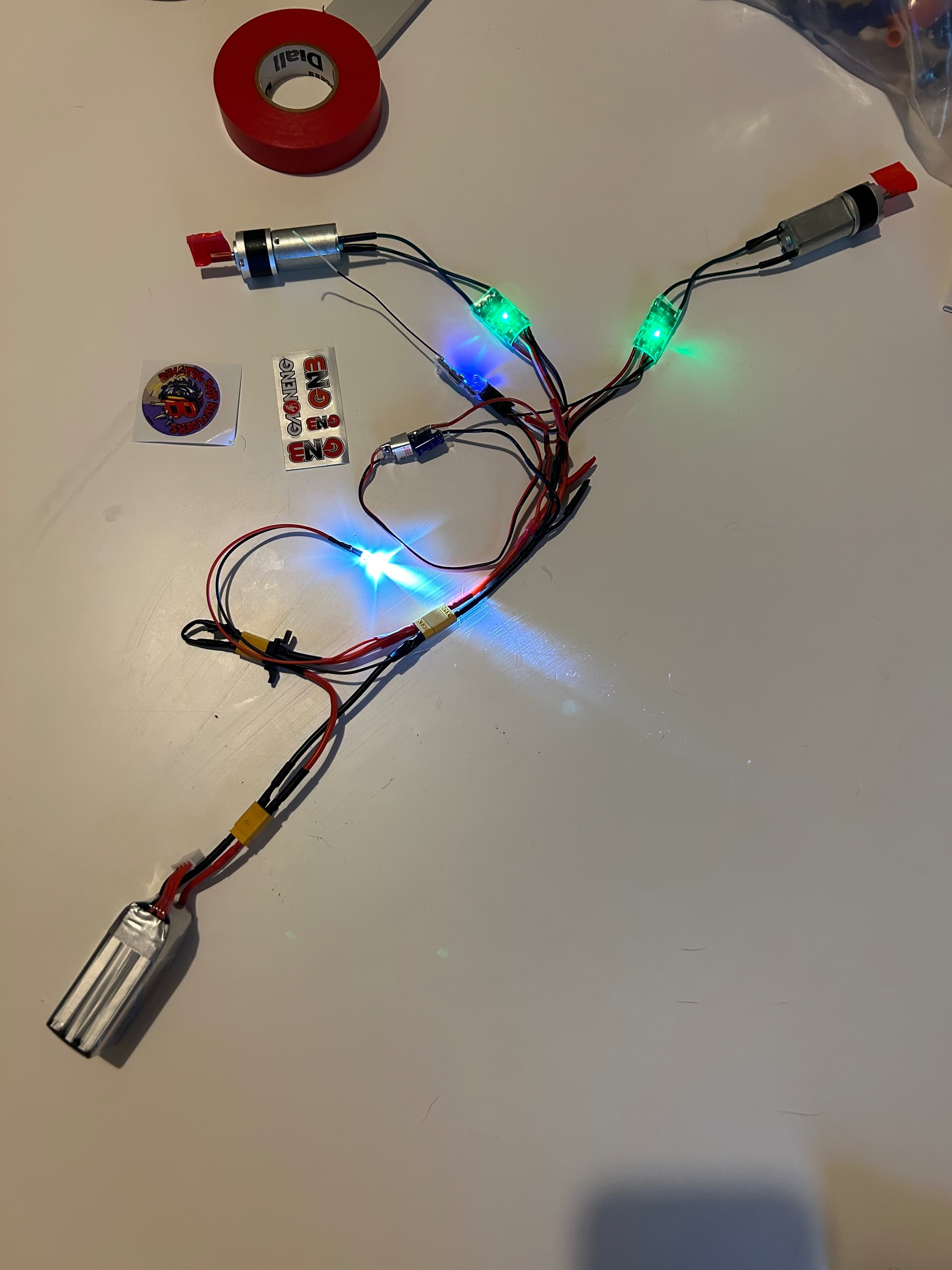
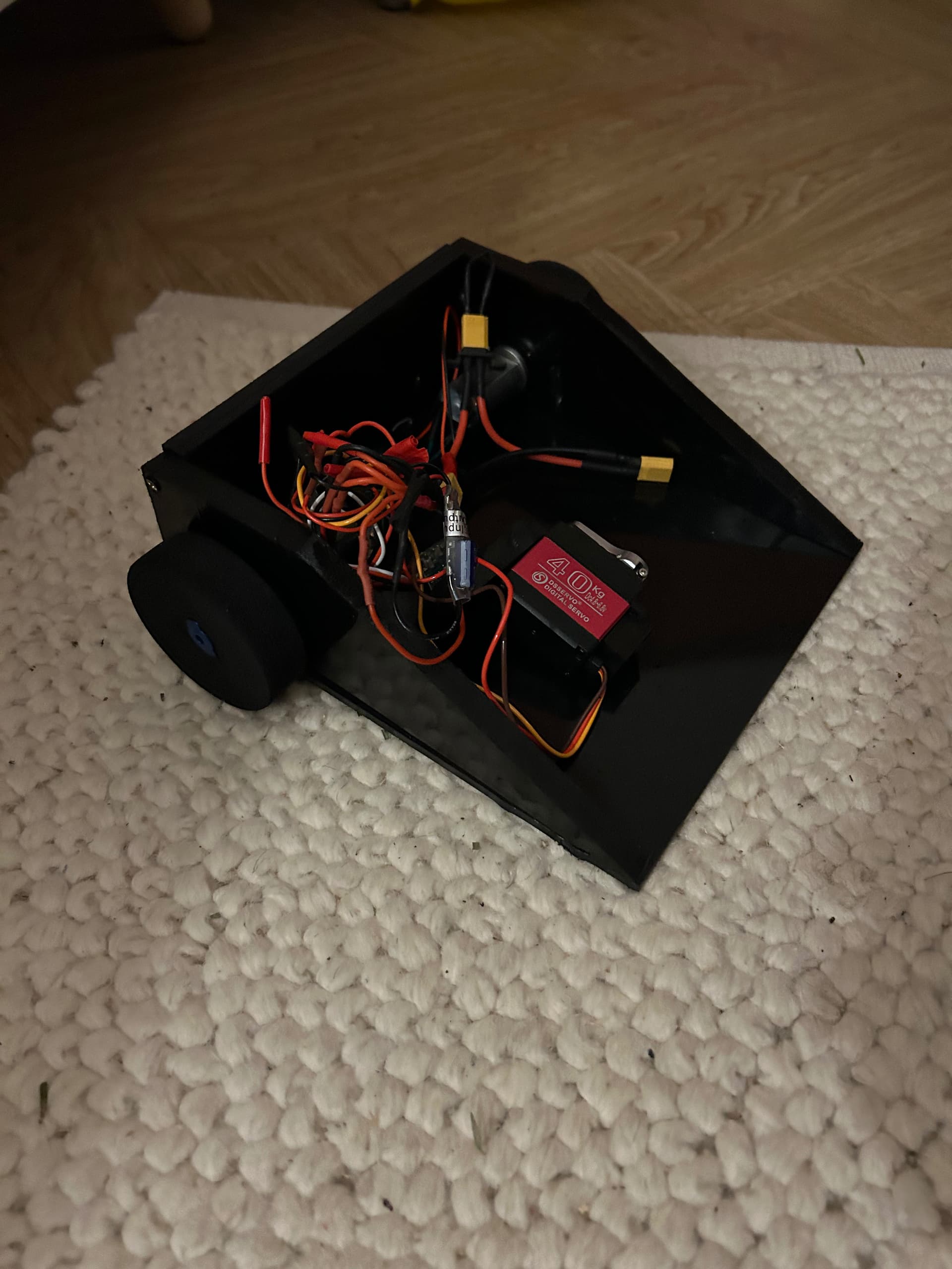
Been away on holiday but am now back and onto the robot. We’ve now got the servo in the circuit and working! A combination of my terrible driving, it’s (assumed) lack of actual lifting power and my fondness for beer have led me to name this contraption Tipsy.
Looks like I’ve got a bit of fun to have with the controller to get the full range of motion, but it works.
Hoping to get the servo fully mounted later on, and then the hinging lifter plate to go with it.
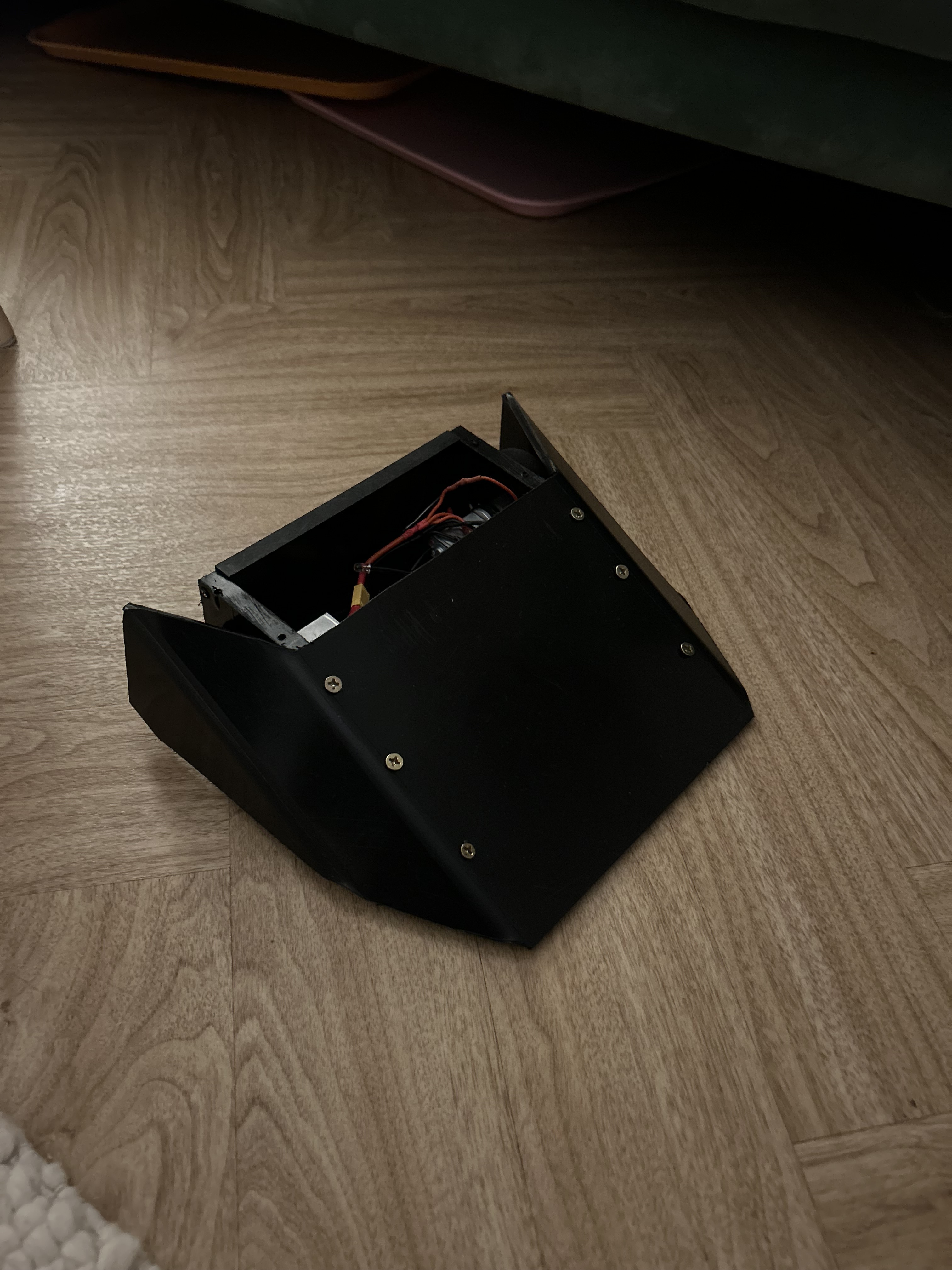
I’ll need to look at solutions for ground clearance at the very front of the thing. Likely going to be a case of finding some steel or something similar (if I can sneak it in the weight).
Need to get a flipper arm built into that front wedge, and then I’m planning on playing with some metals with the remaining weight allowance. Starting to think I’m not far off from watching this thing get torn to shreds in its first battle!
I procured the metals and designed the lifter arm connection. Went to create the metal for the wedge last night and fell foul of Mr Pearce’s sage advice:
building robots is dangerous, and should only be attempted with great care
Got a bit happy scoring with a Stanley knife and have been to A&E as a result…
Strictly at the drawing board for a while now while I come back from that!
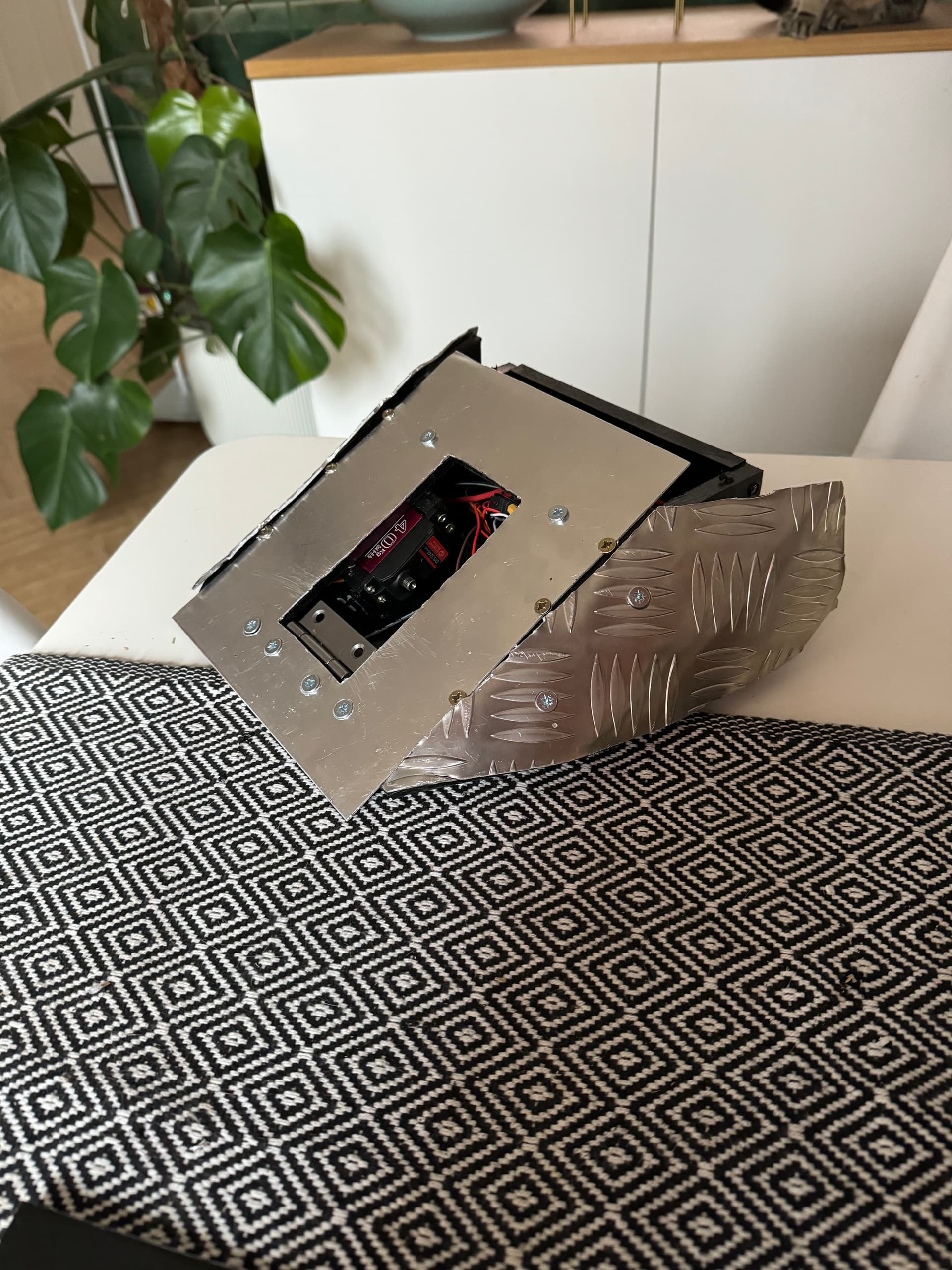
So the injury healed pretty quickly and I hacked away at getting some kind of lifter arm in. Cut up a load of aluminium to use as light armour, too. The net result is a complete mess:
Whilst it works (I’ve since fitted the plate to the lifter arm), it isn’t able to self-right and the ground clearance is pretty huge. Mixing the metals also created a pretty gnarly seam that you can see in that photo.
I’m not particularly pleased with how it’s turned out so am seeking some advice on my next move. In your opinions, do I:
a) Salvage the wedge chassis, get a brushless motor and come up with an axe design to shoehorn into what I already have
b) Keep the wiring, bin the rest and spend the time learning everything I need to CAD and 3D print/CNC something from scratch that’s a bit more polished
c) Fine tune this design until the lifter will self-right, fight it and use the lessons learned to implement A or B
While I really enjoy the aesthetic of the checkerboard metal, my personal preference is keeping the HDPE as armour - it’s bouncy and absorbs hits and your robot looked super clean with the curved side pieces!
Personally I’d go with option C - I think with a bit of extra linkage you’ll be able to make it self right. Front hinges are much harder than rear to get that full self right - have you got a servo extender now? How much range are you getting from the servo?
I definitely agree. Think I’ll pare the armour back and maybe just wrap a tiny bit of steel at ground level. I’ve experimented this evening with reversing the hinge and if I were to rotate the servo around, I reckon it would just about make it. I have the servo extender, so am getting 90° each side. I assume there’s a way I can map it on the transmitter to start at -90° and move all the way through rather than starting centered?
The easiest way would be to use channel 4 on the receiver (rudder - left/right on the left stick) then you’ve not got the sprung stick.
EDIT: I was clearly tired, I meant on ch3 and throttle for it to not be sprung!
If you prefer to control it with throttle, you may be able to do it with throttle curves (5.8 in the manual) I’ve not personally tried on that transmitter