Hello everyone,
Welcome to the build diary for the featherweight robot Flipperpool.
This is my fourth featherweight and with every new build I do I like to always experiment and learn something new, this time it will be pneumatics and air compressors.
The brief for this robot was:
Feather weight 13.6kg, sportsman, suitable for BEVS and Robot’s live shows.
Four wheel Drive : based on my other robots I have had more success and prefer this style of driving.
HDPE and barrel nut construction: This is the build style I am most used to, and it suits a robot that will not be seeing full combat
Air compressor Flipper: I wanted to build a flipper, but without the hassle of storing and refilling CO2. The concept of an air compressor robot is quite uncommon and I thought it would make the robot’s design stand out.
Unconventional shape: Most pneumatic flippers tend to be a triangular wedge, this is an effective design but I wanted to be different.
Initial Design Concept
The design for Flipperpool actually came from my pneumatic ant weight robot Aaaaaaaaaaa!, which was in turn inspired by some of the American flipper robots on battlebots like Bronco and Lucky.
Link to the antweight: https://www.gentlewayrobotics.com/copy-of-marauder
This antweight was more a proof of concept that I could fit pneumatics into a 150g robot, it could produce massive flips, but ran out after 4 flips reducing how competitive it could be in real tournaments. Despite this I really liked the shape of the robot and decided to make Flipperpool a scaled-up version of it.
Build materials
-
5,10 and 20mm HDPE sheets
-
5mm polycarbonate sheet
-
M6 bolts and barrel nuts
-
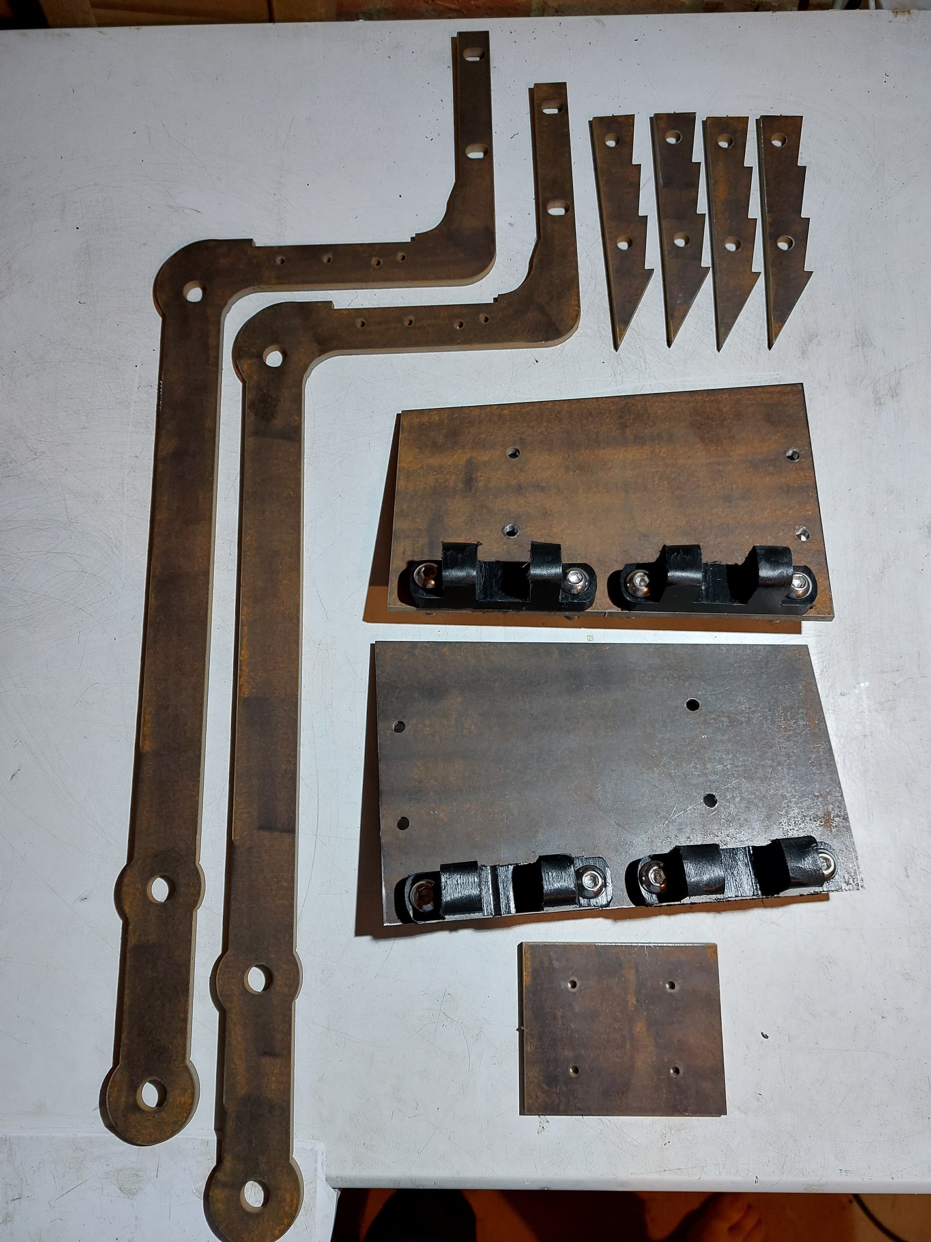
Water jet cut Hardox
Standard materials for a BEVs style featherweight, Hardox for the weapon and front plates and polycarbonate for the lid so you can see all the fancy pneumatics.
Drive system and electronics
-
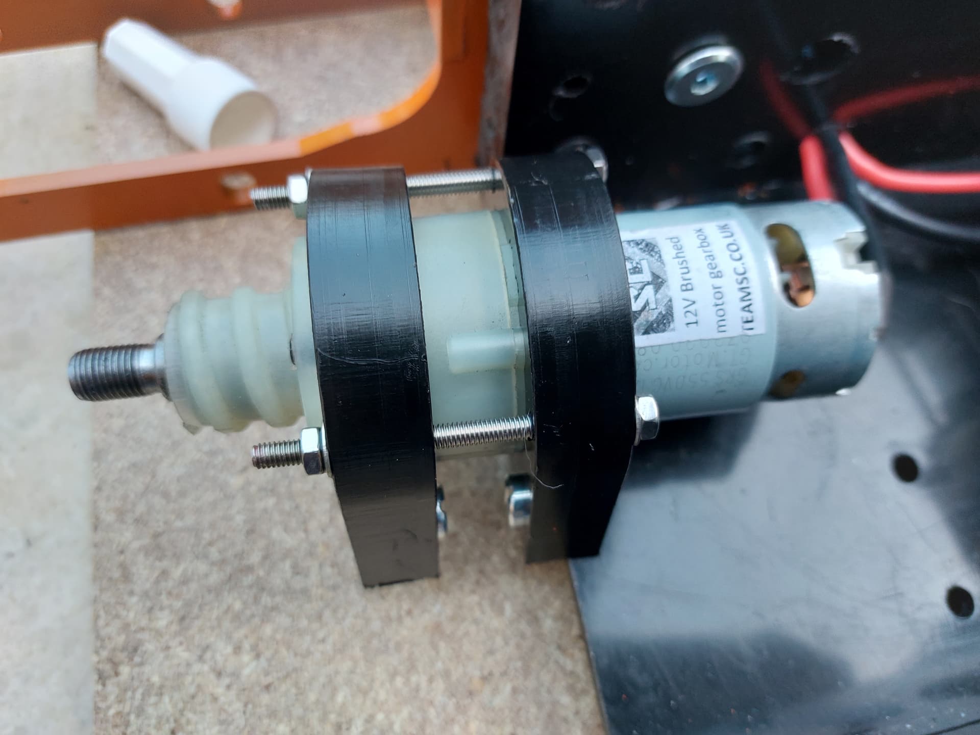
4x 12v drill motors with mounts and 100mm wheels (https://teamsc.co.uk/)
-
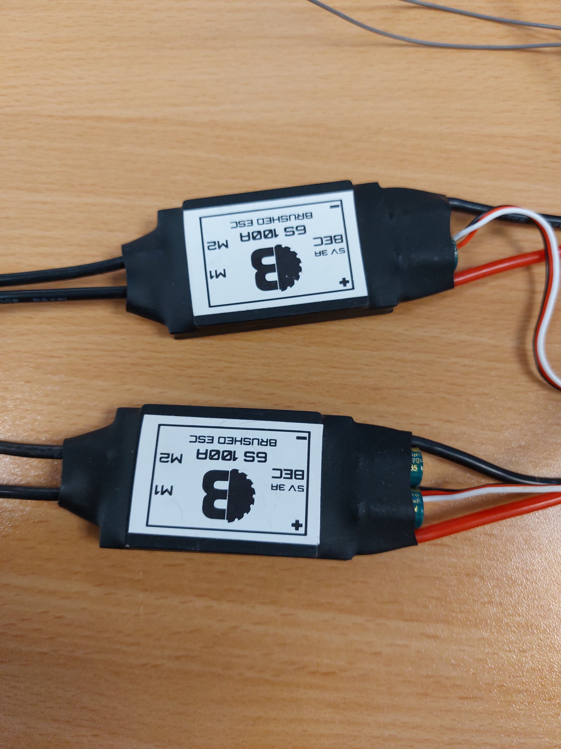
2x BBB featherweight Brushed ESC (Featherweight - BBB Shop)
-
4s 70C Lipo (hobbyrc.co.uk)
-
Flysky Receiver (AliExpress)
-
Flysky FS-i6 (AliExpress)
-
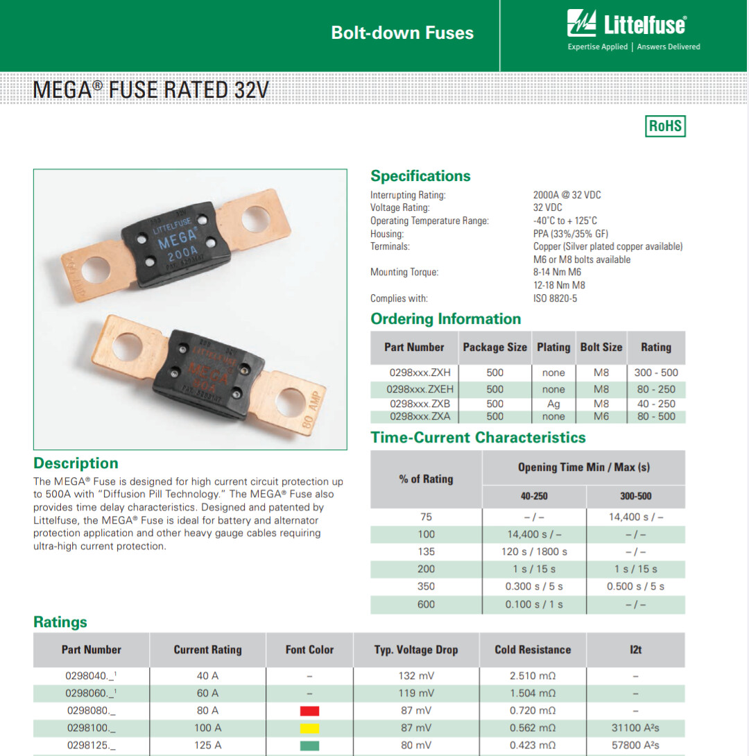
100 amp blade fuse (from a fellow builder)
-
12v LED (already had a huge stash)
-
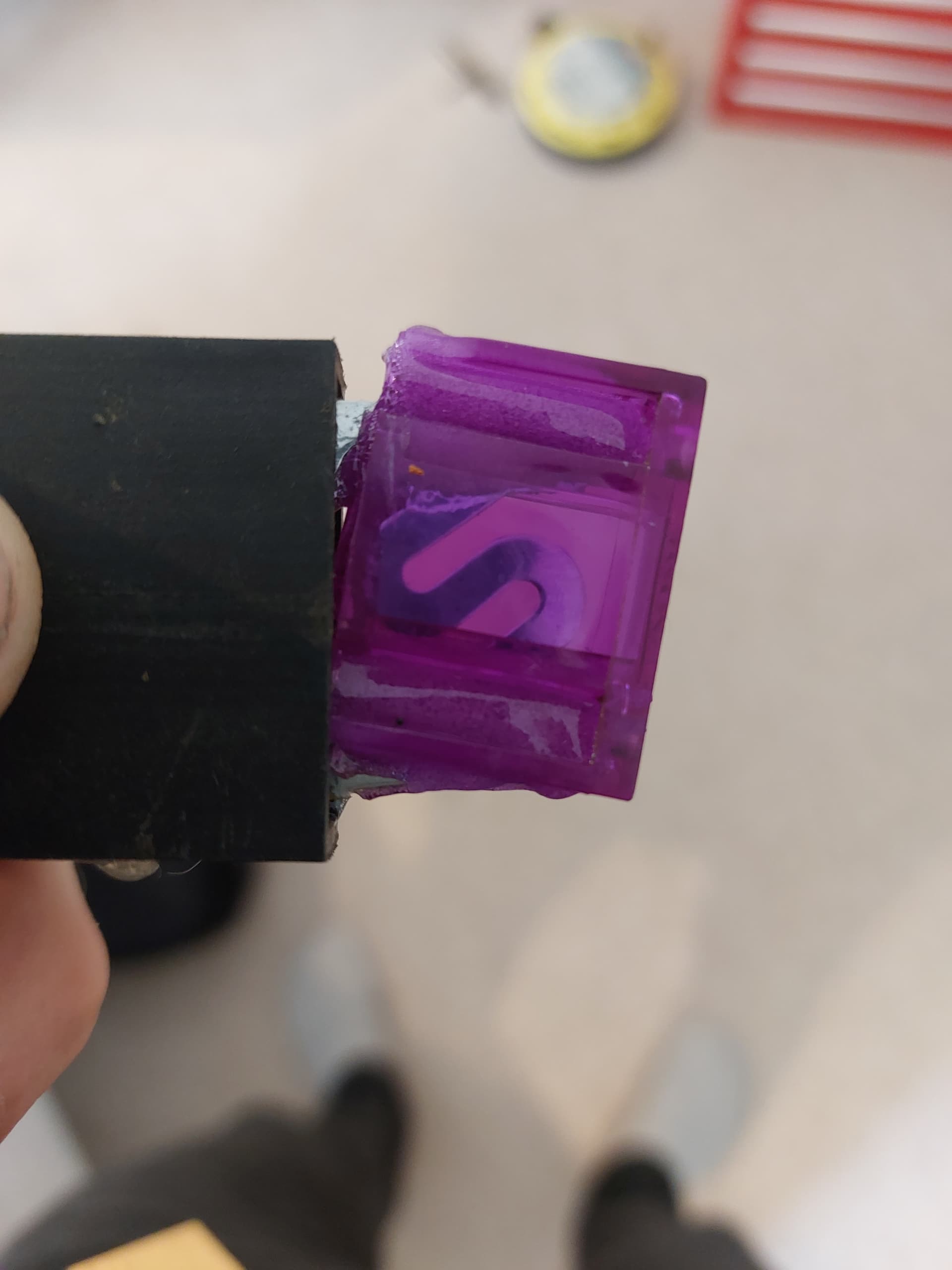
Xt90 removable link (eBay, modified with 3d printing a resin potting)
-
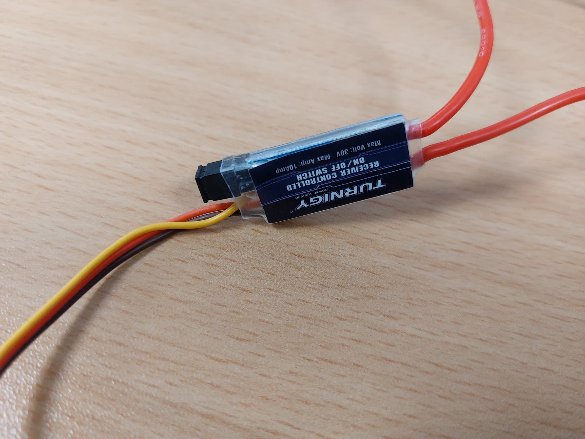
RC on off switch 5A, for triggering the flips (eBay)
I went with drill motors instead of brushless drive, I have made brushless driven featherweights before, but I always found I drive them too carefully as I’m too protective of my expensive drive. So, I decided to go for cheap and easy drill motors and have fun raging the hell out of them. I have the option to upgrade too brushless later.
Pneumatics
-
VIAIR 00098 98C Compressor (eBay)
-
Pneumatic ram bore 40mm stroke 80 (Fellow Builder)
-
1-10 Bar adjustable NO pressure switch (eBay)
-
0.25L PCP Paintball tank (eBay)
-
3 way 2 position solenoid valve (ebay)
-
8mm pneumatic hose and fittings, including ball valve for dumping air (various locations)
I experimented with lots of cheap car air compressors before going for the VIAIR. All the cheap ones eventually failed or lied about the pressure they could produce. The VIAIR is expensive but very well made, reliable and easily delivers 10bar (BEVS limit).
I went with the smallest paintball tank I could find, the tank doesn’t need to be very big for a compressor bot as you are constantly refiling, going too big could actually be a disadvantage.
A ram was selected as a balance of force and speed, too bigger bore left the robot in danger of becoming a lifter instead of a flipper. I would love to tell you I did all the calculations for this… But in reality I just copied what I saw in other successful lower pressure robots and presumed they had worked it out.
The adjustable pressure switch is important, this shuts the compressor off when the pressure is reached, it can be adjusted with an Allen key.
Diagram
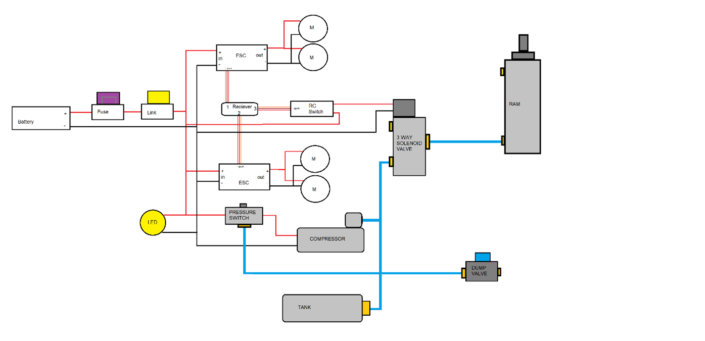
The diagram shows all the electrical and pneumatic connections.
blue lines are pneumatic hose.
CAD
I modeled Flipperpool in SolidWorks.
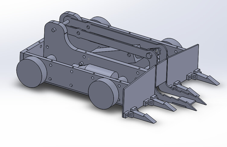
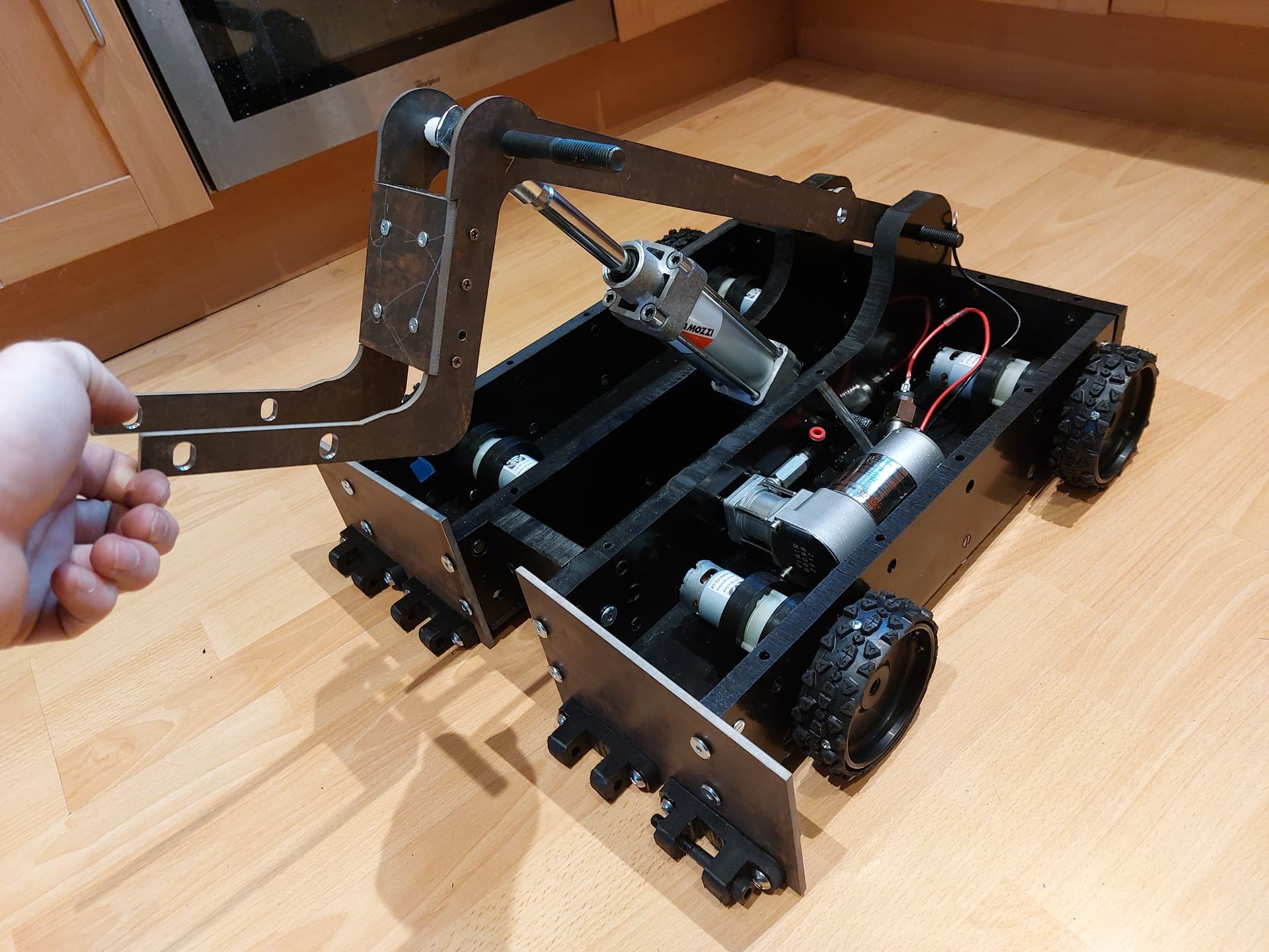
I first designed the flipper arm mechanism, since the flip on my ant weight worked so well I literally scaled it up by the difference in pneumatic ram size. I used to hdpe bulkheads to house the mechanism, I also included two sets of mounting holes for the ram so I could experiment with greater lift (back mounted) or power (front mounted).
With this assembly made It was just a case of fitting all the parts I had selected into the smallest HDPE box I could around it. All construction will be done with barrel nuts. The front plates will have mounting holes with the option of mounting wedgletts.
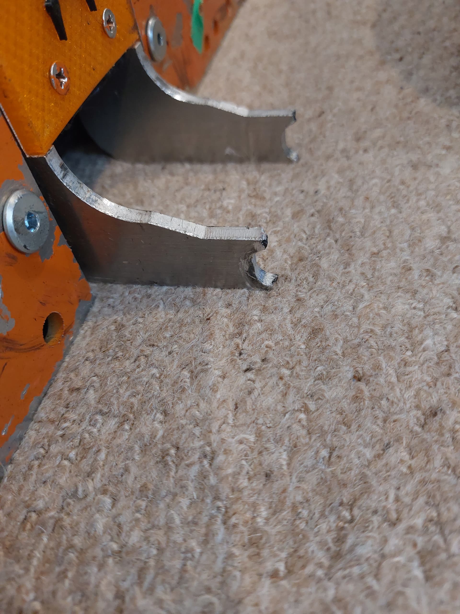
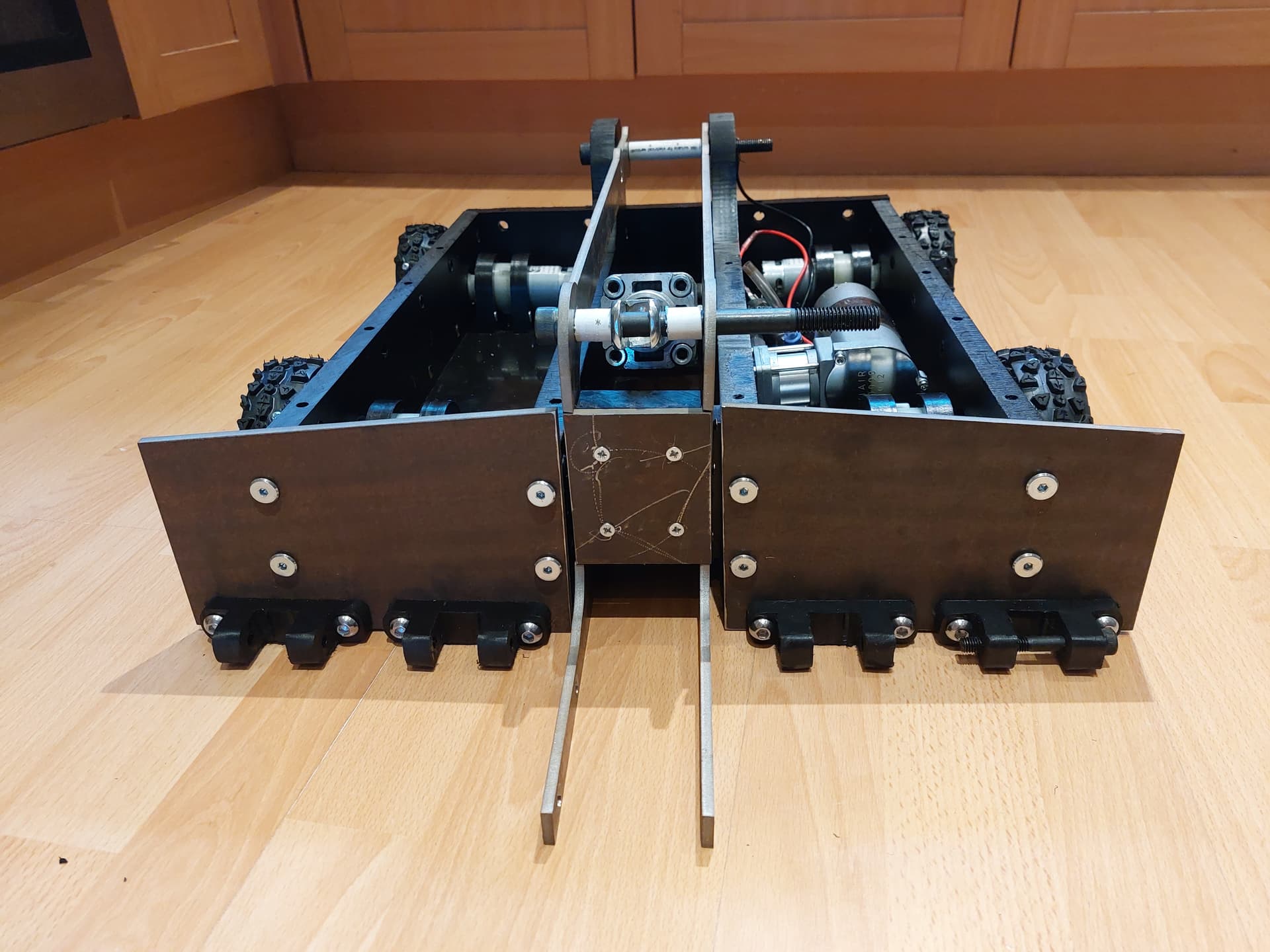
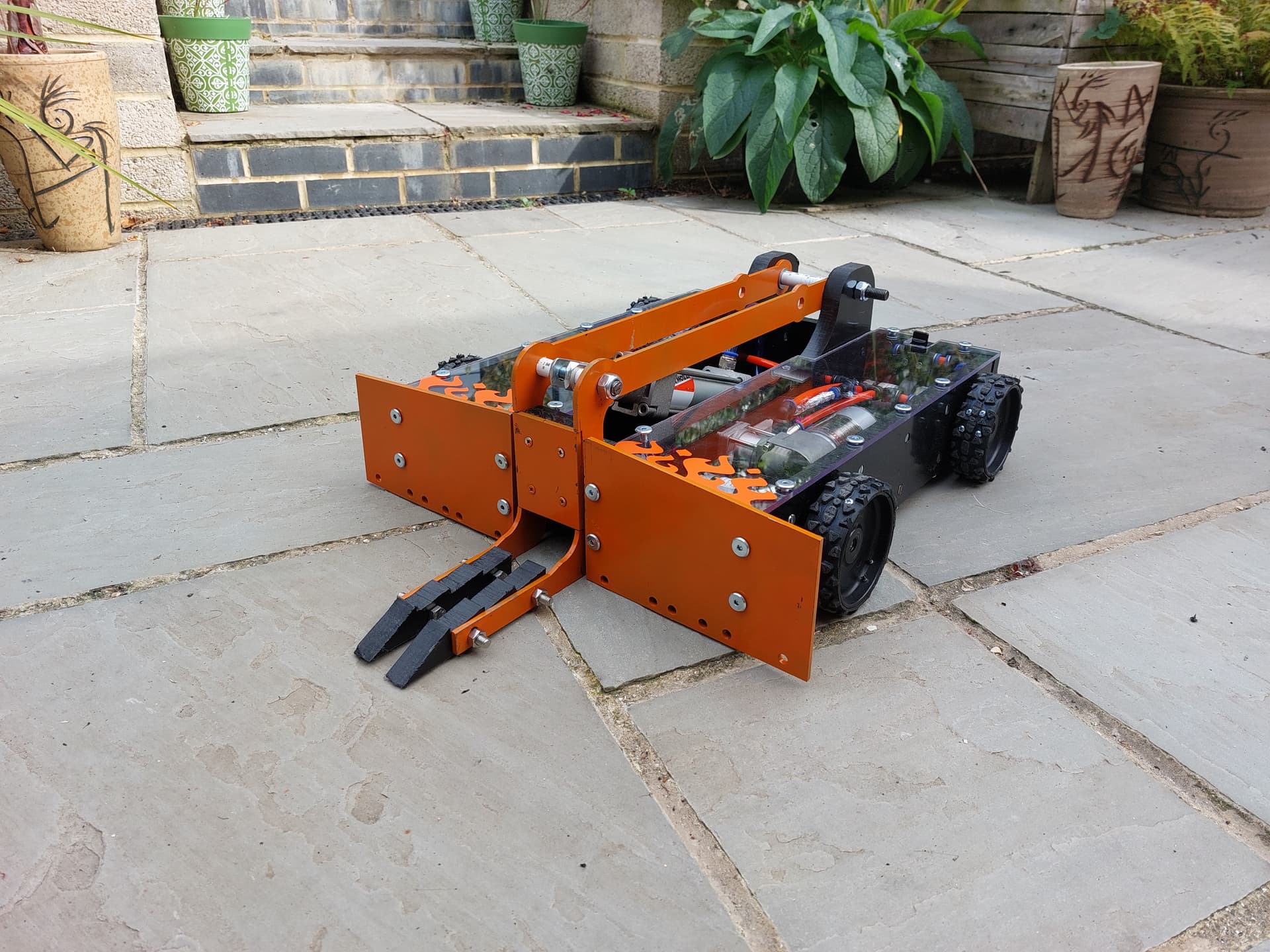
I didn’t make the flipping arms sharp, instead I added oval holes where I could add floating wedge attachments. This gives me the option of creating different fork set ups, with the floating aspect keeping them low to the floor.
I made sure to try and keep the weight balanced with even distribution of parts on either side of the robot.
After assigning weights and materials to parts SolidWorks put the robot in at 13.8kg, which I believed would be close enough to begin construction. More on the weight later……
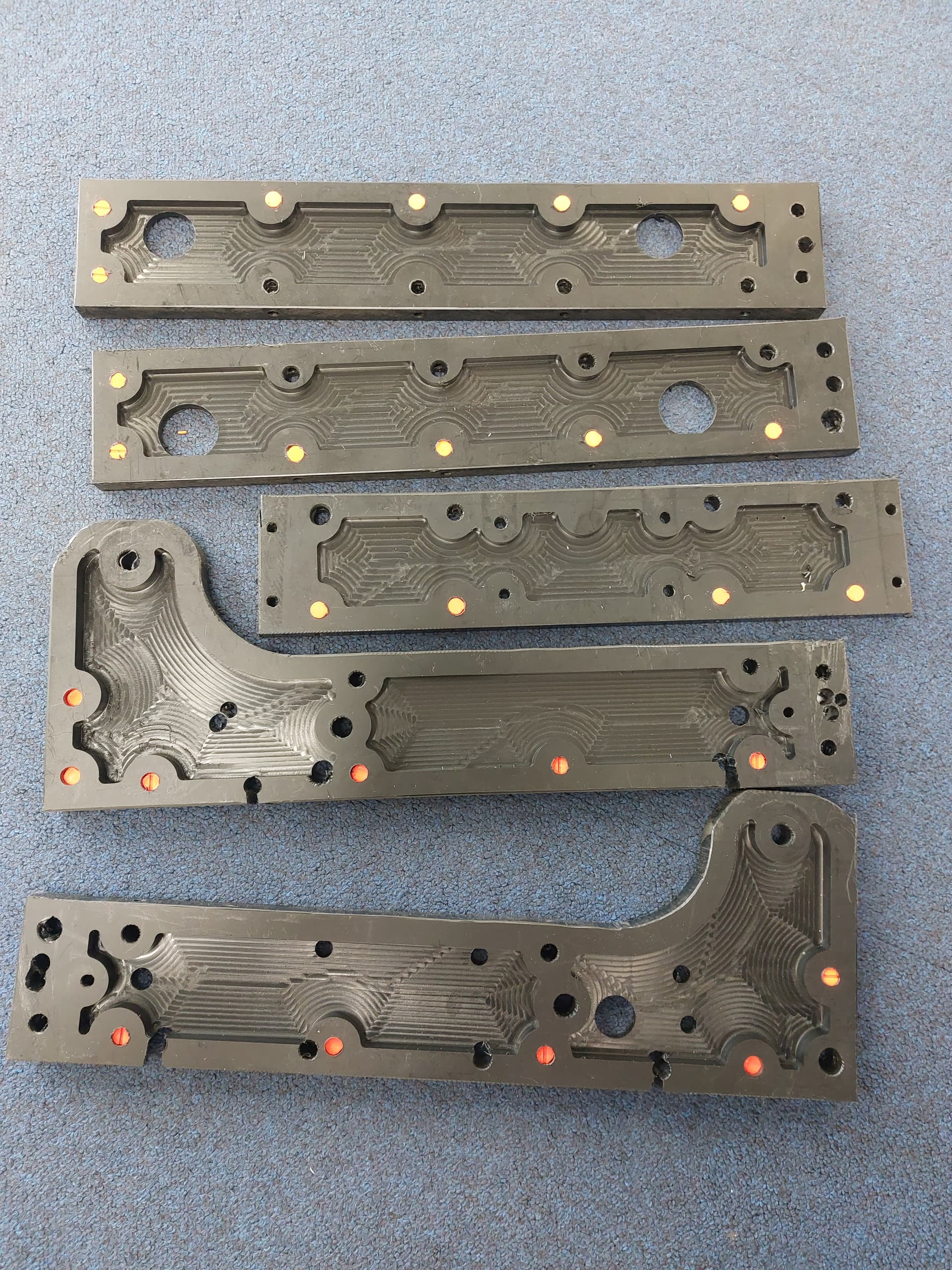
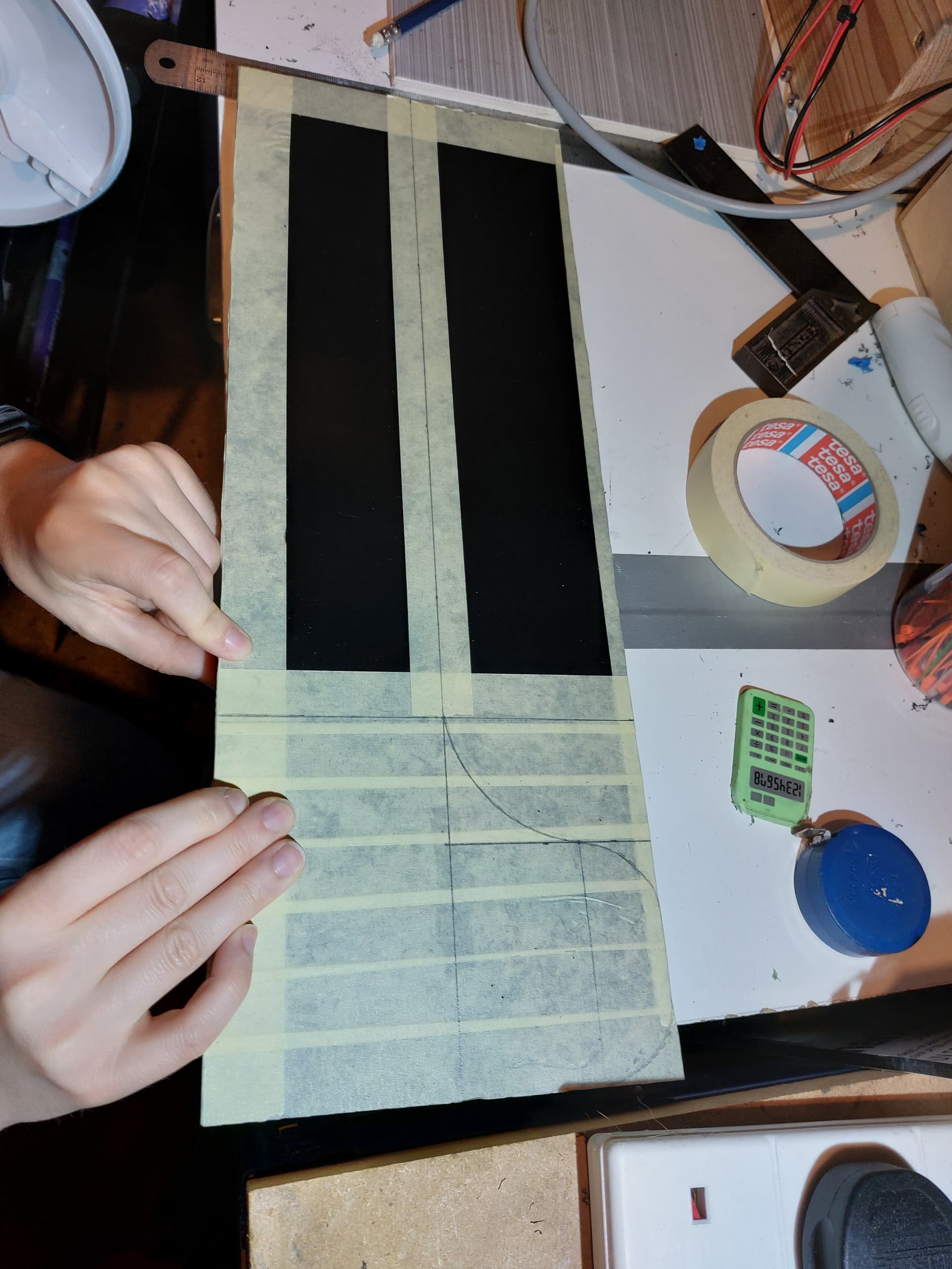
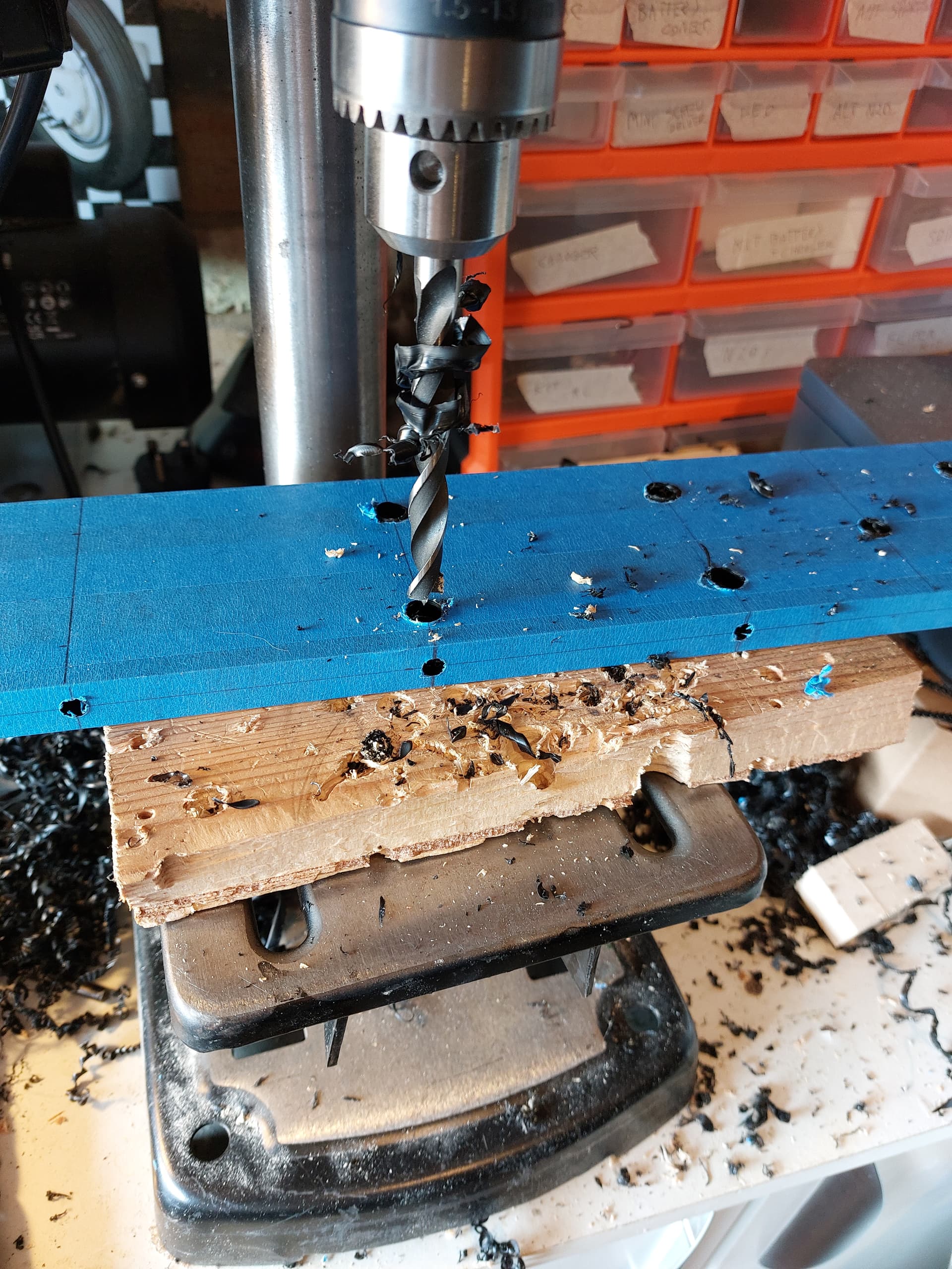
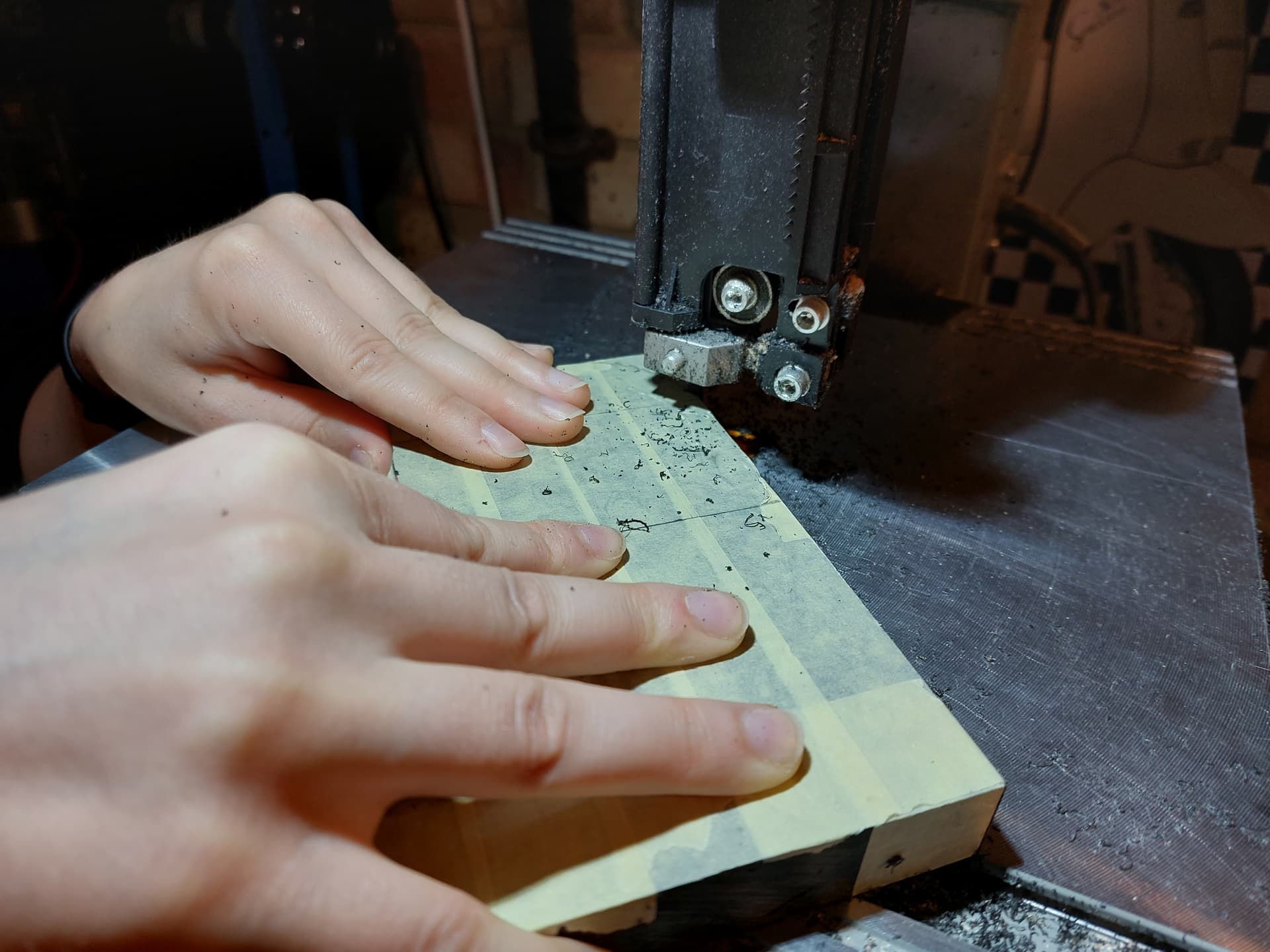
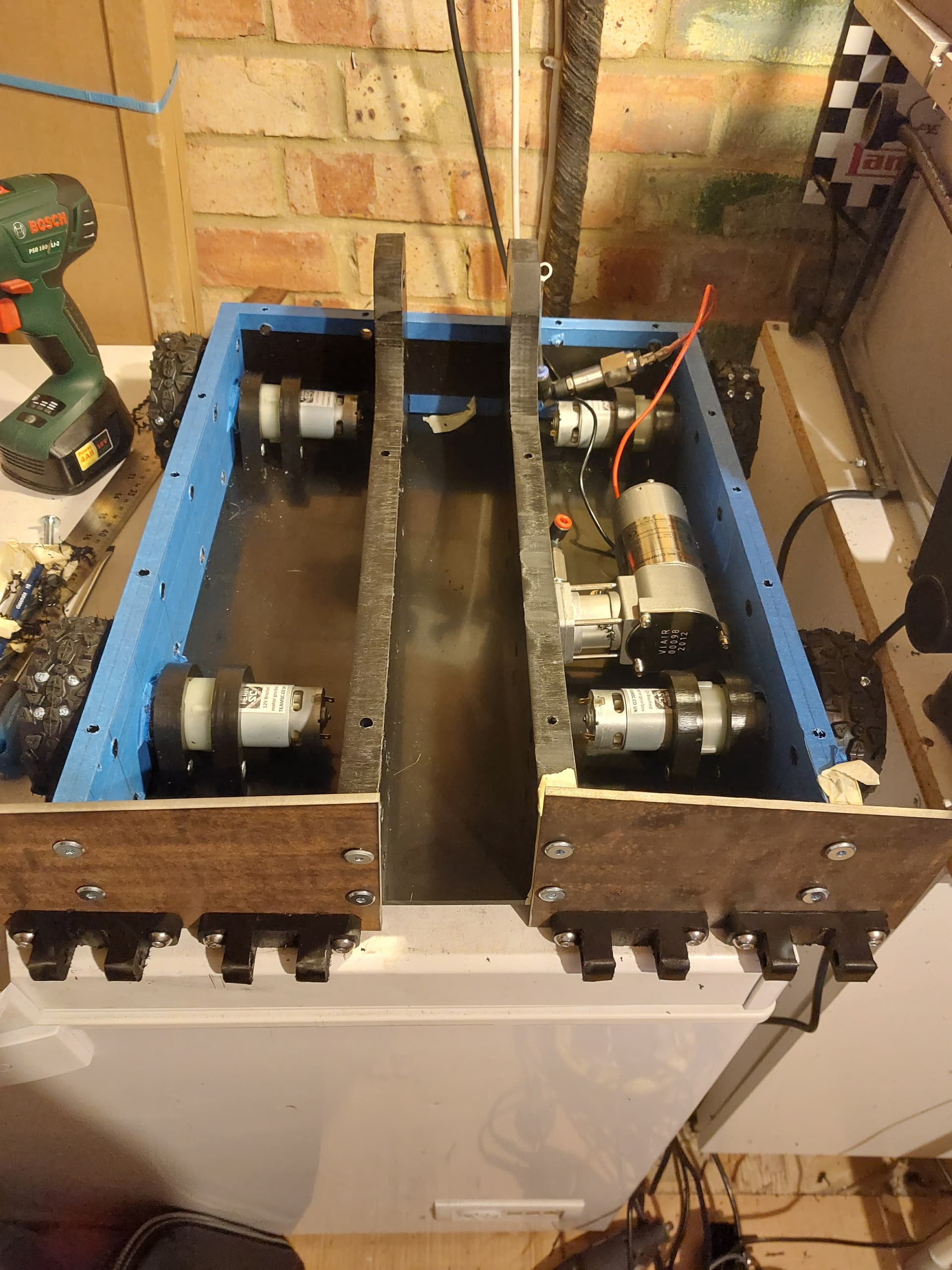
Building
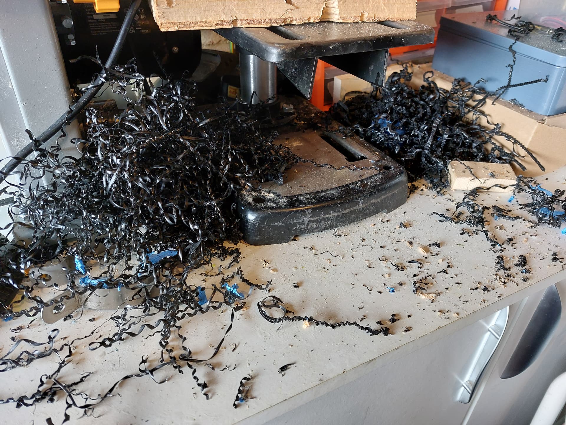
Most of the building work consisted of covering HDPE in masking tape, marking up from the CAD drawings, then cutting and drilling with the band saw and pillar drill.

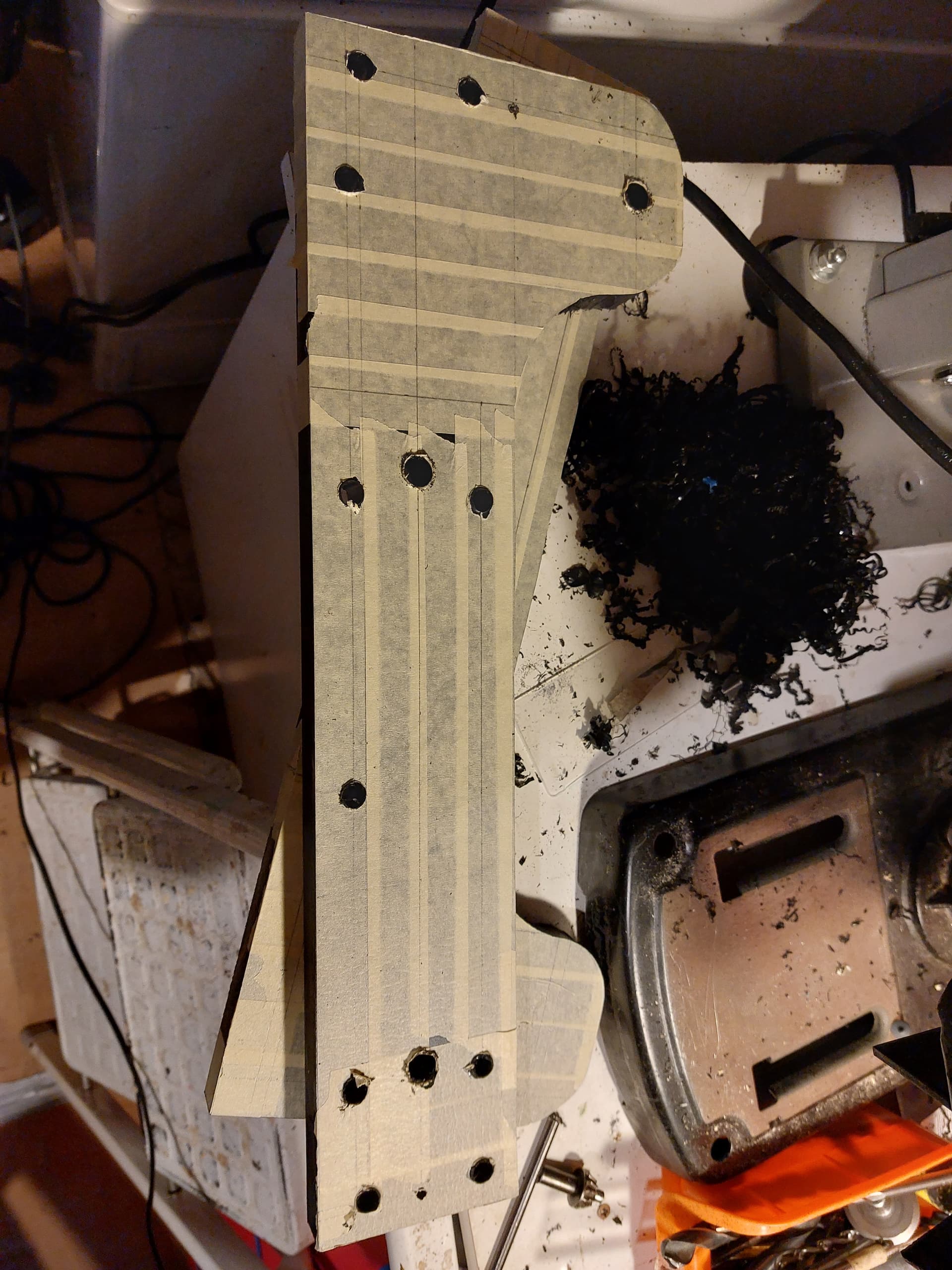
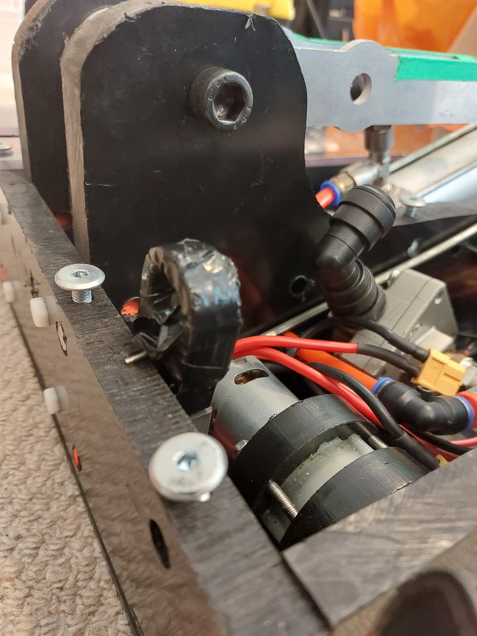
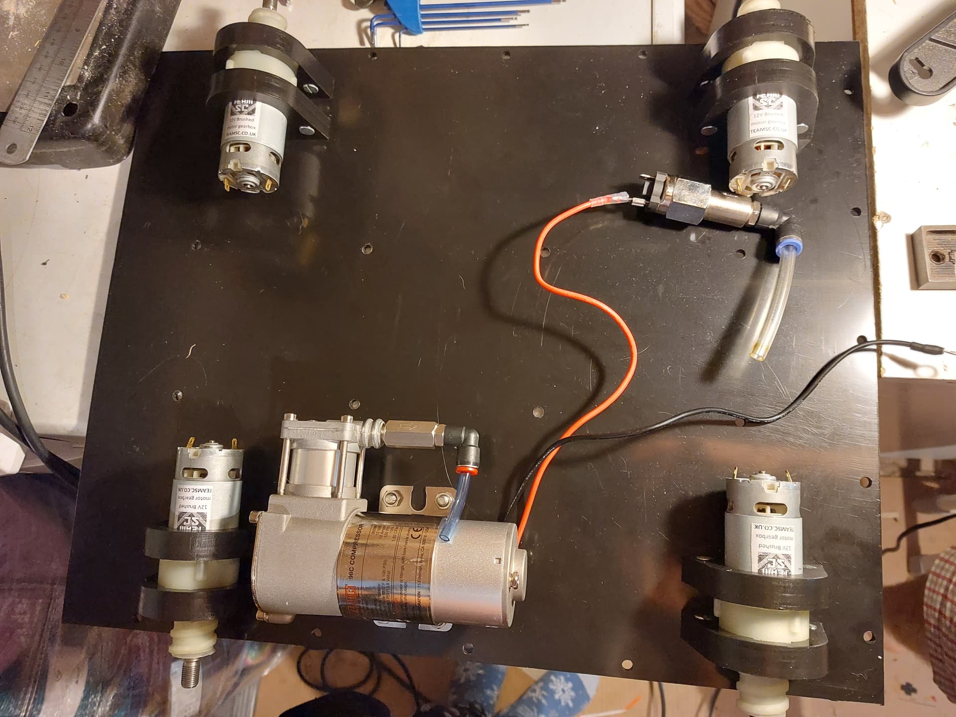
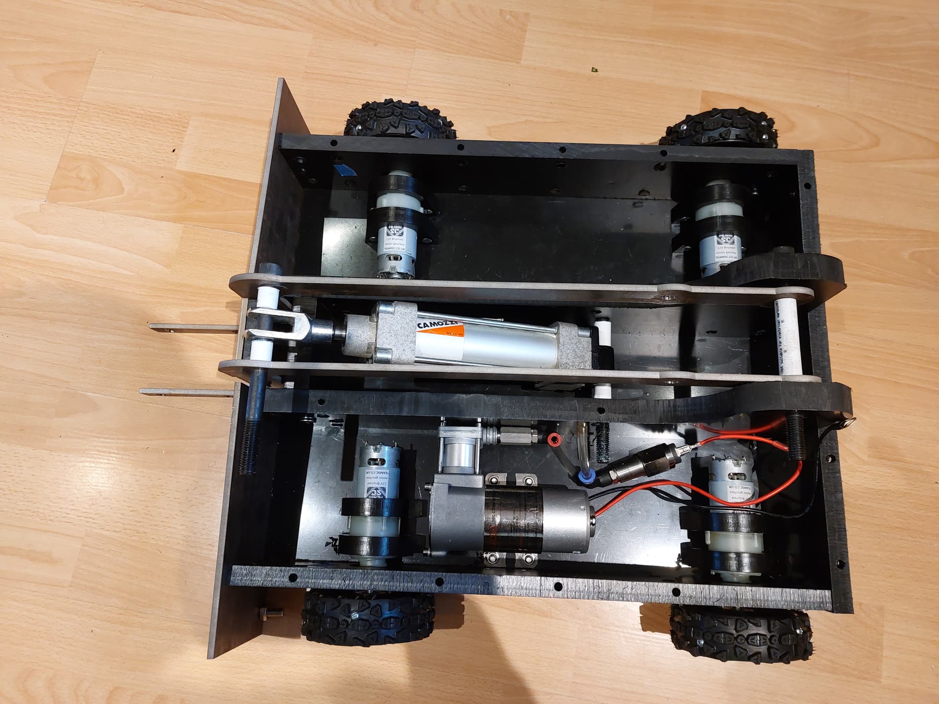
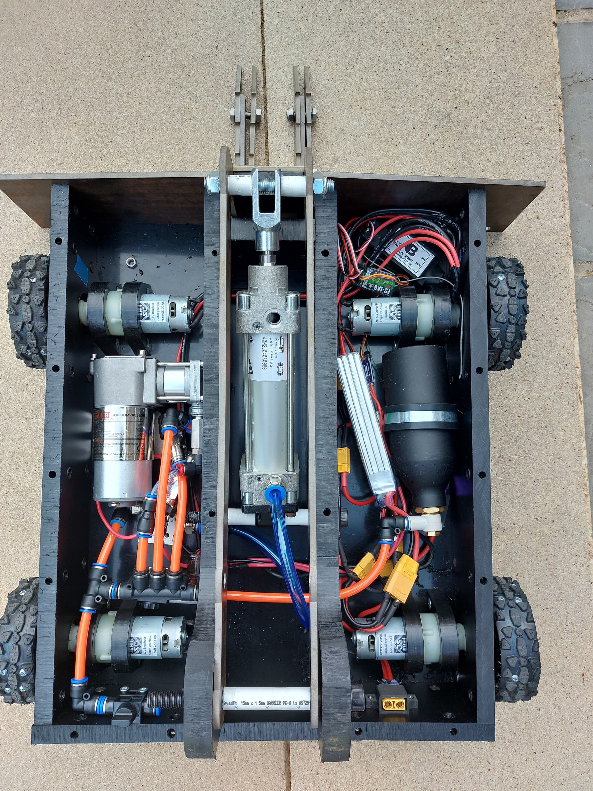
Backplate drilled with motors and compressor mounted
HDPE gets everywhere
Water jet parts arriving
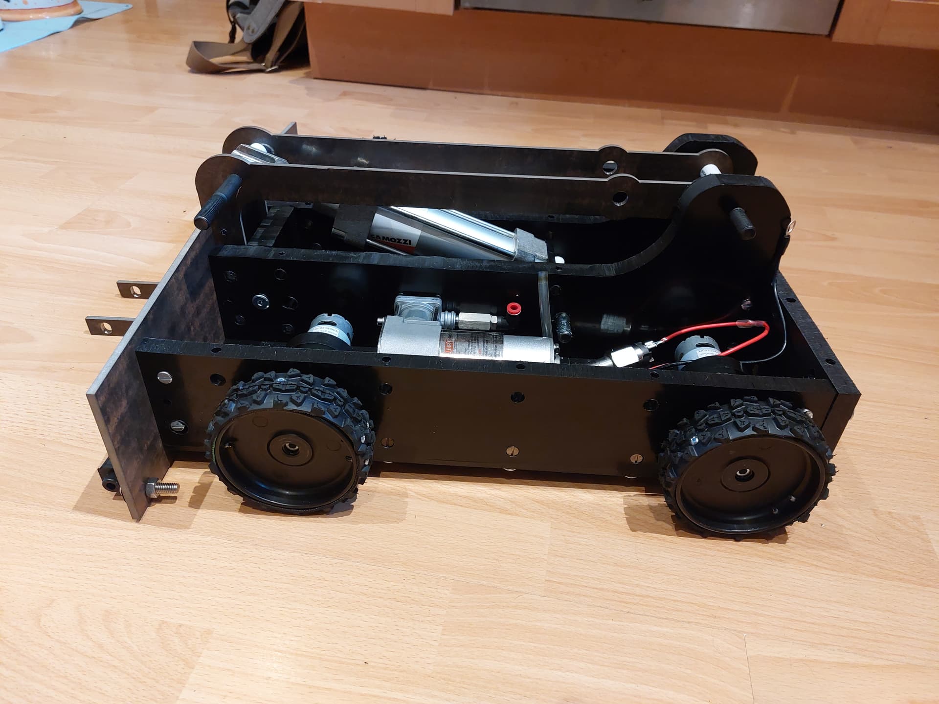
Uprights and front plates mounted
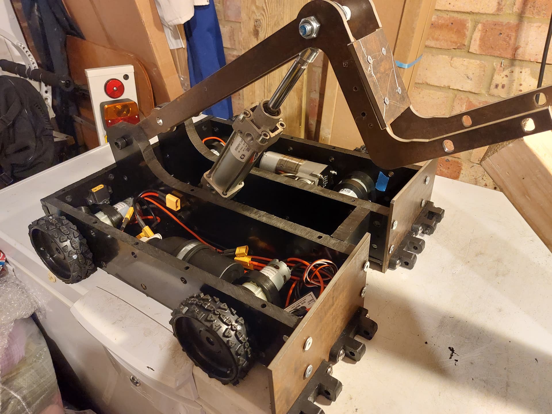
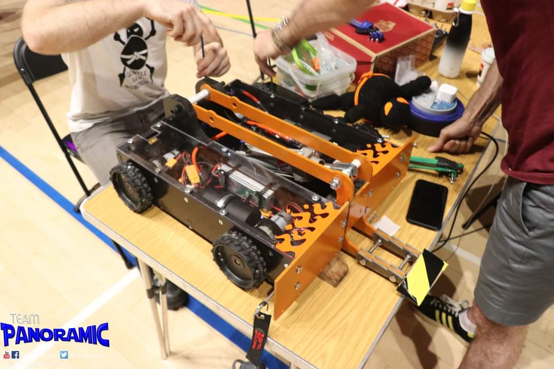
Arms and ram mounted
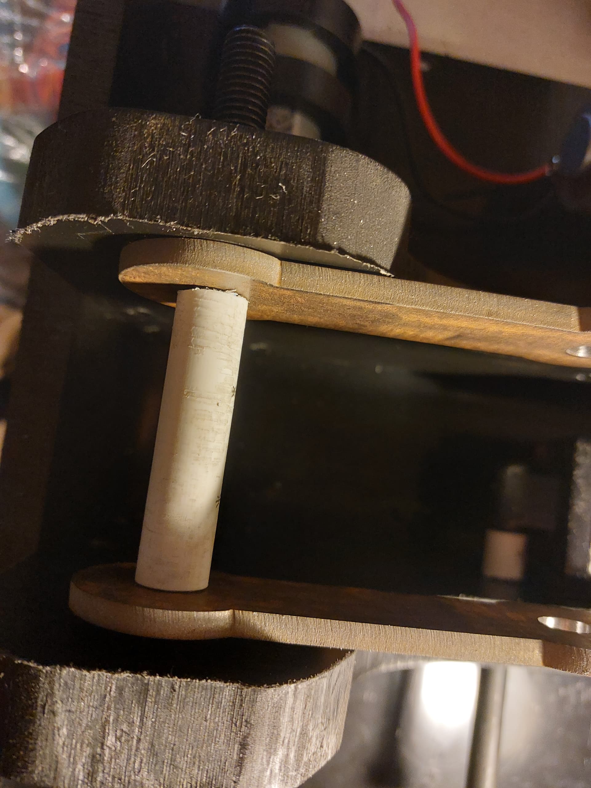
A spacer was made using a piece of PVC tubing that happend to have the perfect inside diameter.
These ESCs are fantastic, much better than the Chinese ones I used previously.
Breakout cable for the drive and weapon wiring.
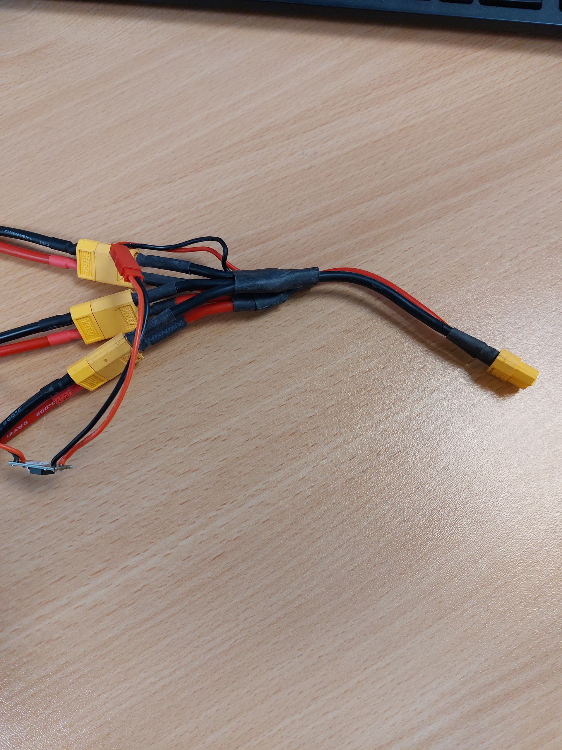
RC switch used to trigger the solenoid valve.
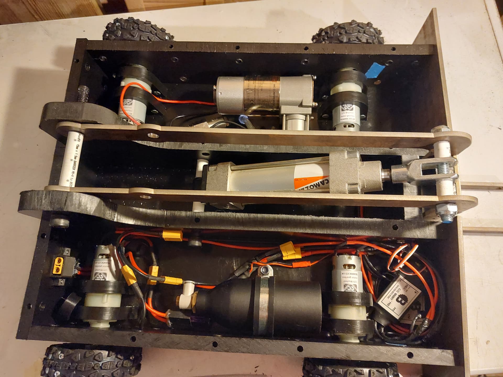
Air tank and drive wiring added
Testing the ram’s mechanism
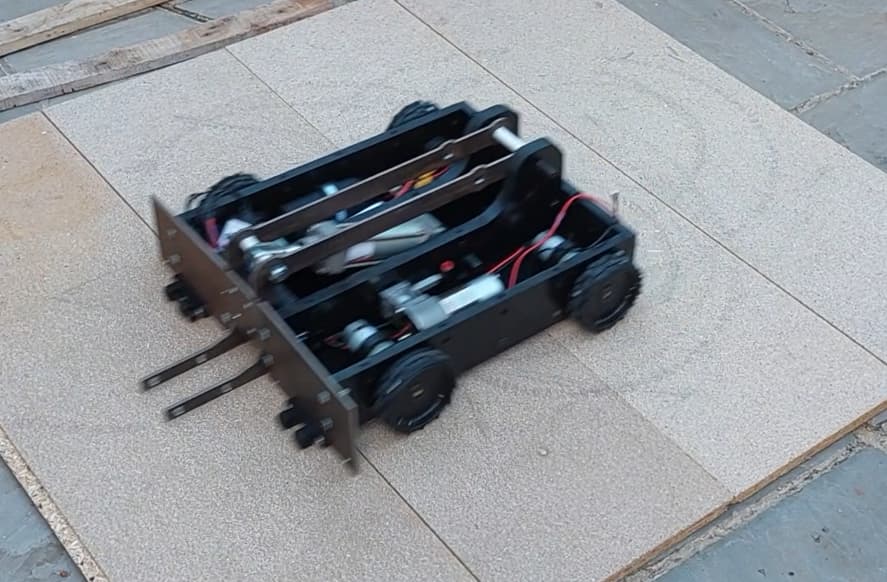
Drive testing
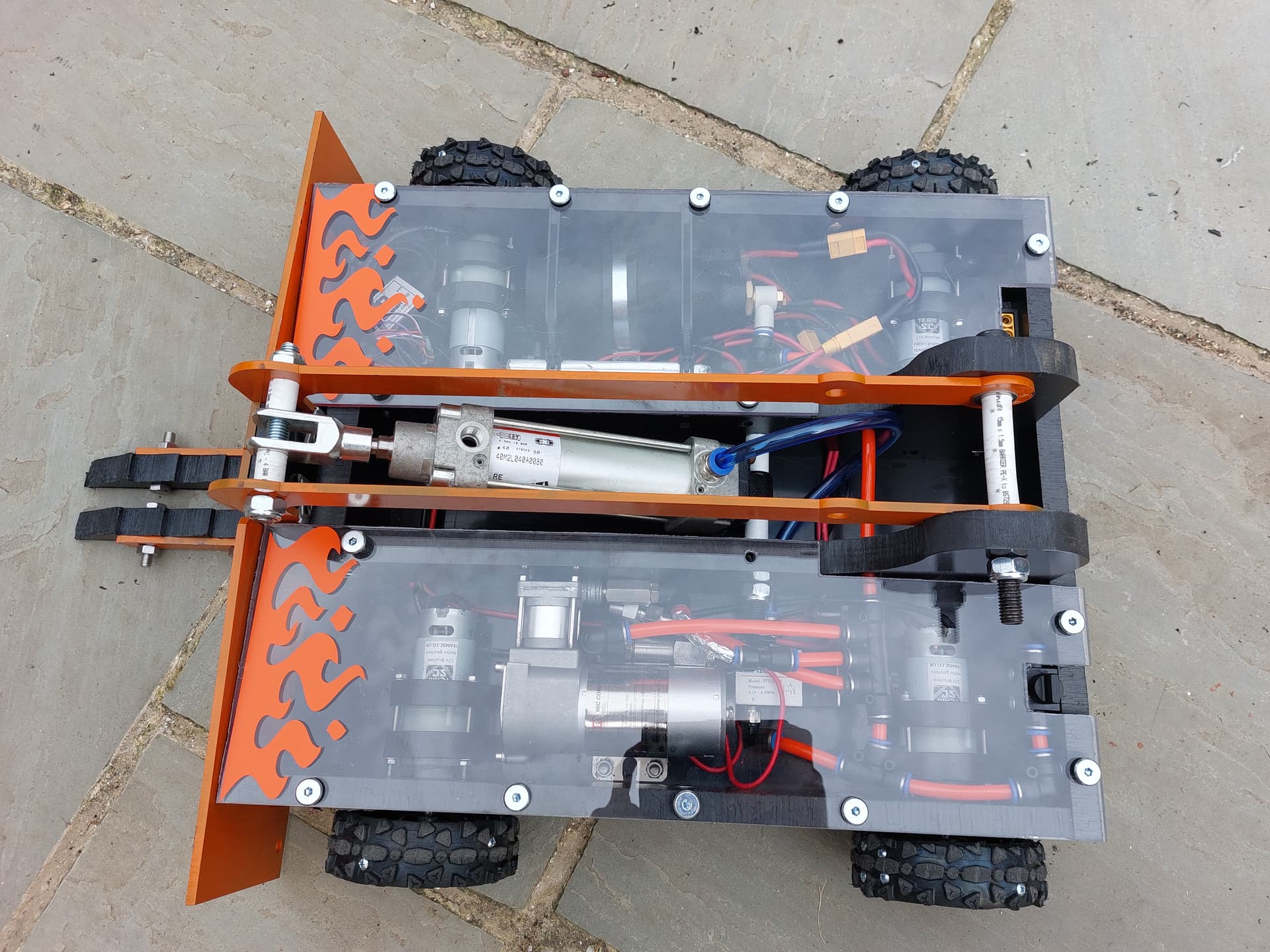
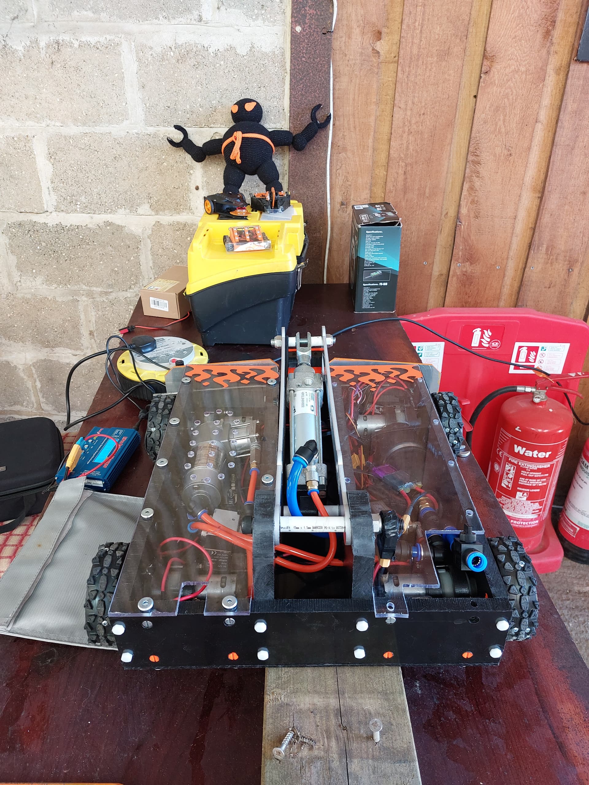
All pneumatics added
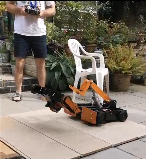
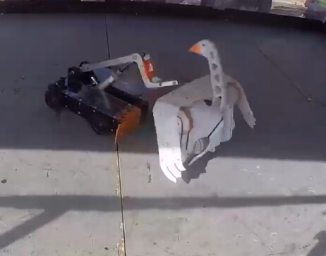
Flip testing.
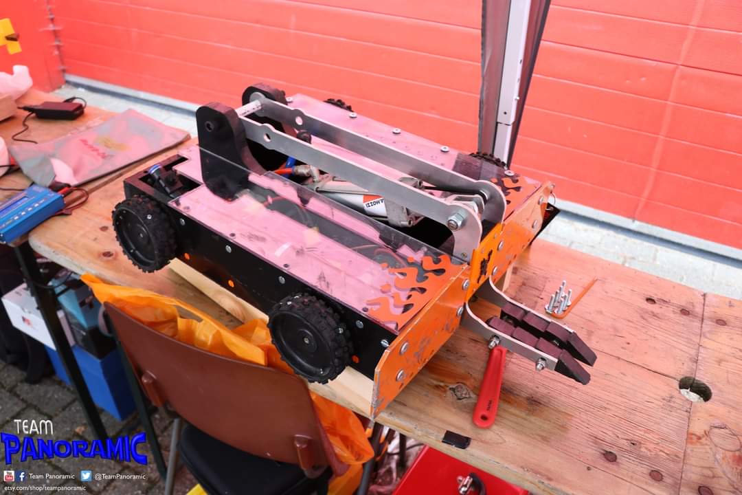
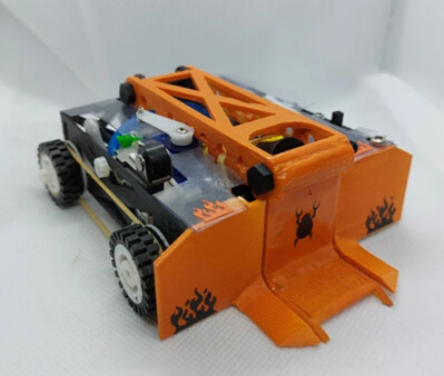
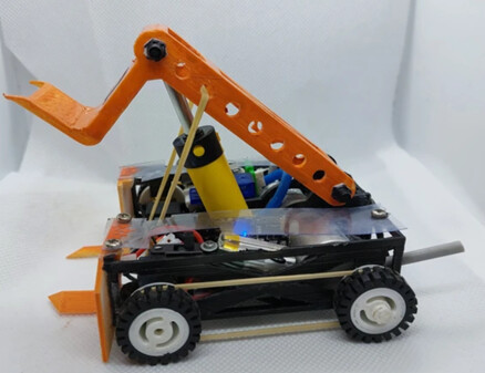
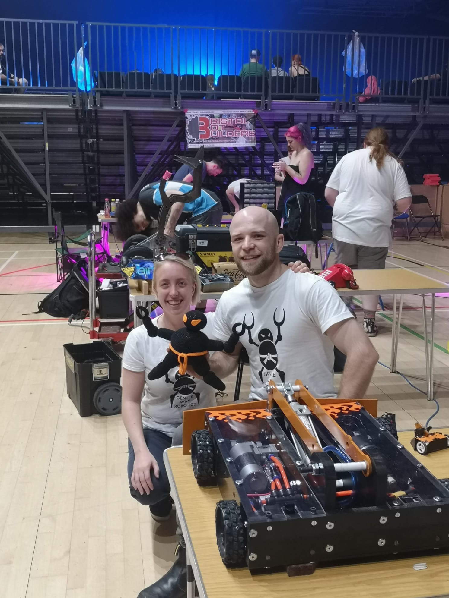
Finished robot photoshoot
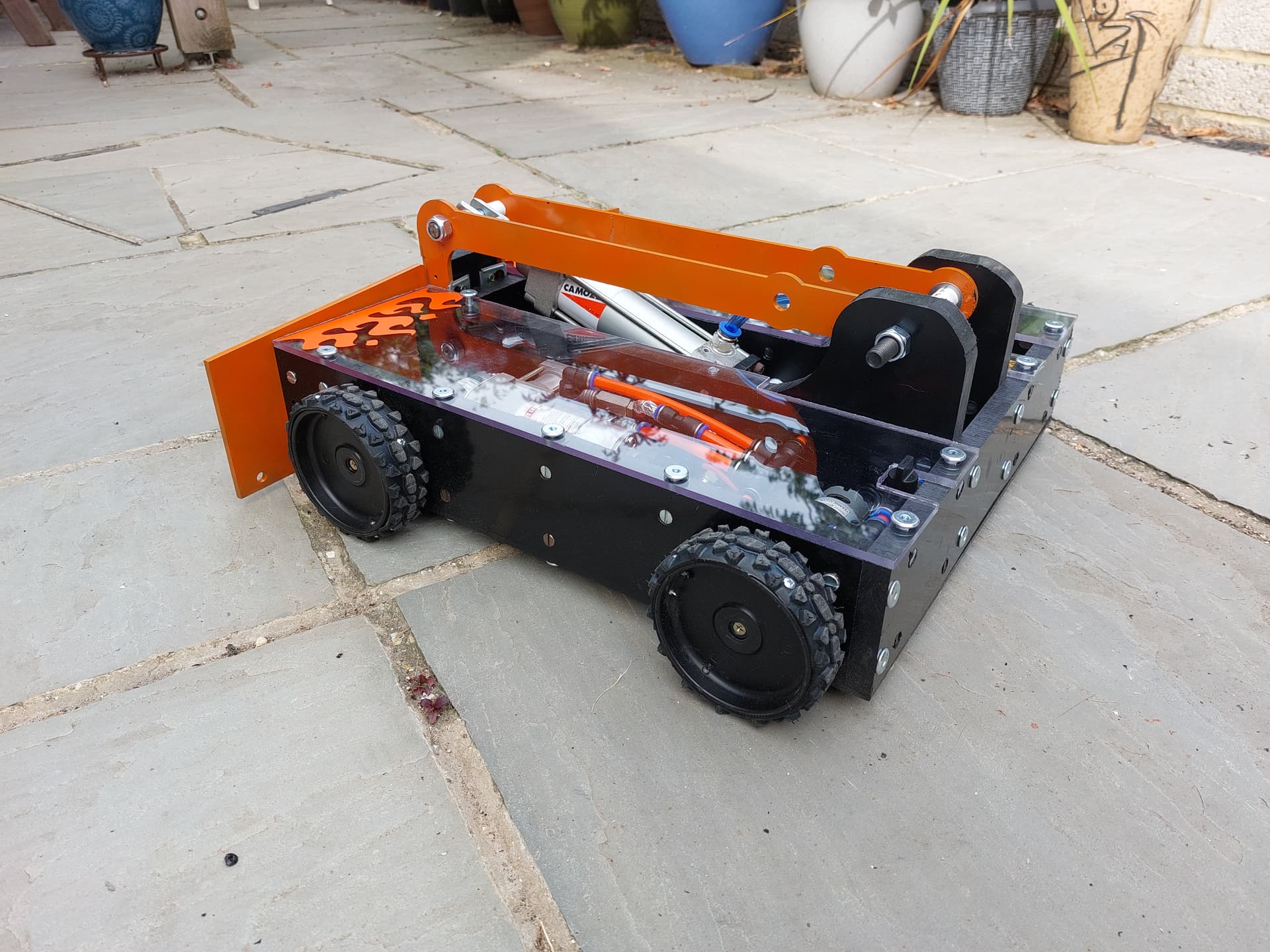
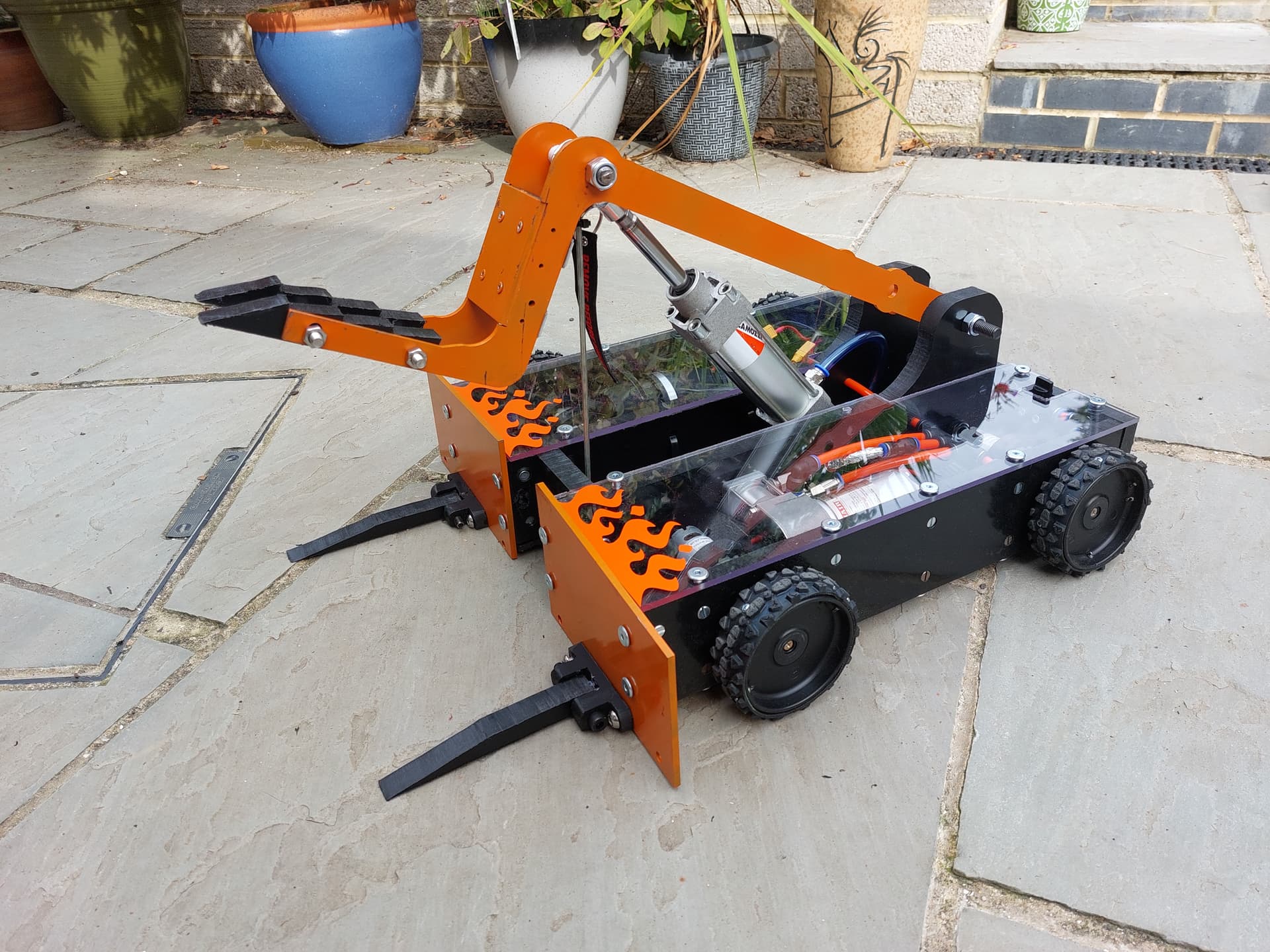
More Pictures: https://www.gentlewayrobotics.com/copy-of-propellant
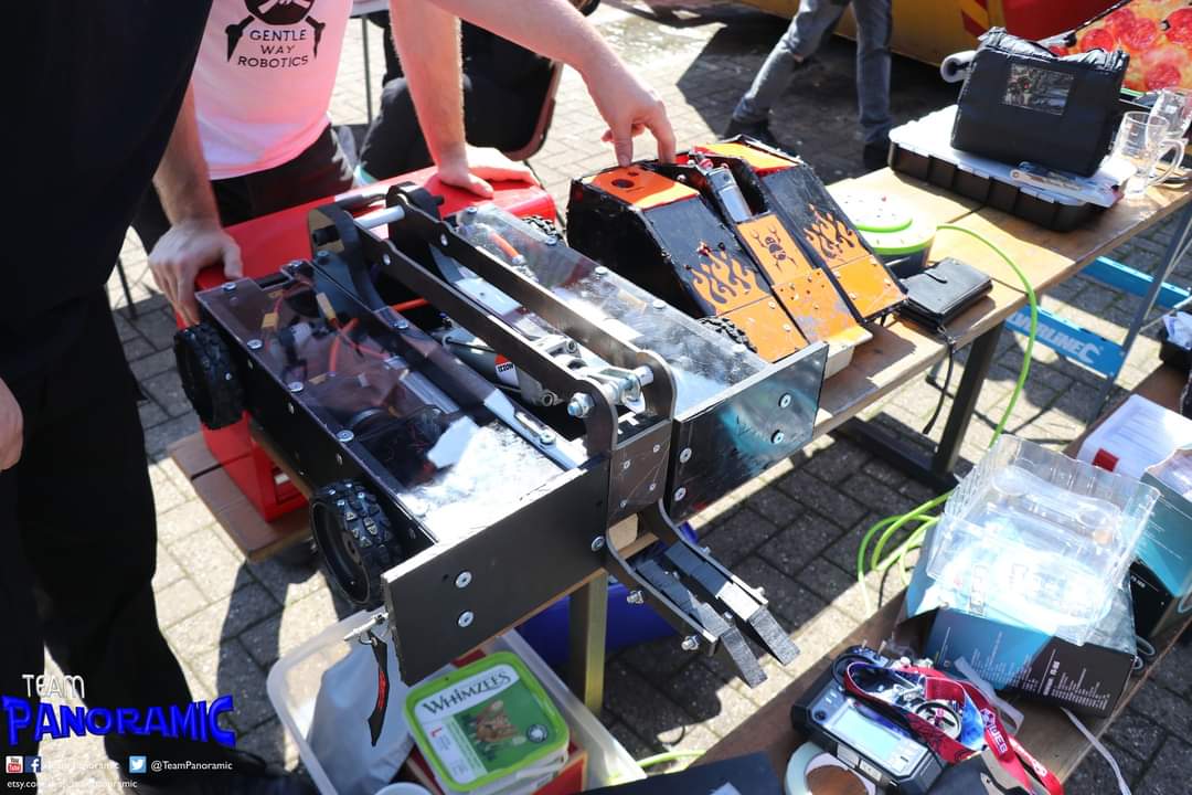
1st Event
The first event Fliperpool took part in was the BBB event BEVs at the left hand screw.
The event went about as badly as it could…
Firstly the robot was a massive 3kg over weight, I had assigned the wrong material to the Hardox on my CAD model and the whole robot’s calculation was wrong. I didn’t have time to get more parts ordered before the event, I made some makeshift HDPE front plates to get some of the weight down. Fortunately the organizers let me send it in anyway.
Testing went well in the arena but as soon as it had its first fight we lost both drive and weapon within a minute…
The loss of drive was due to the gearboxes separating from the motors when the robot met resistance. This was because the grubscrews were not in tight enough into the clutches. Unfortunately the screws had ripped the thread out of the gear boxes and they could not be repaired on the day.
The loss of weapon was because the air hosing being to close to the compressor. The compressor got extremely hot and it melted through the hose.

Fortunately I had another featherweight propellant I took with me so I still got some robot fun at the event.
Post 1st Event Upgrades
After the event the gearboxes were repaired by adjusting the grub screws and adding bolts to the motor mounts to prevent them from separating.
The hose was re-routed around the compressor to prevent the heat building up and the Hardox parts were replaced with aluminium to bring the weight down.
2nd Event
The 2nd event was Robots live at Crawley. This is my local event, I can almost walk to it!
This event went a lot better.
The weight was much better, we were still 500g over weight but robots live is a lot more relaxed about weight.
The drive worked the whole time and proved very nice to control.
The weapon worked, but proved very underwhelming. It acted more as a slow lifter and even more disappointingly failed to self-right the robot on several occasions. Unforgivable for a flipper robot!
UPGRADES
After Robots live was a long break with plenty of time to upgrade the robot. I was now very happy with the drive of the robot, but these areas needed improvement:
- Flipper needs more power
- Weight needs to be reduced
- Heat needs to be better vented from the compressor
To improve the flipper it was deemed the issue was with the air flow, it had enough power to lift other robots but it requires greater airflow to increase the speed of the flip. To do this the 8mm air hose was upgraded to 12mm hose to get the air into the ram faster.
However simply changing the size of the hose was not enough, the size of the ports on the solenoid valve were smaller than the inside diameter of the 12mm hose, that means the airflow would be limited at this point and upgrading the size of the hose would be pointless.
Using a larger port 3 way value was a solution, however this valve was so big it would have been impossible to fit into the robot.
Instead a pneumatic dump valve was utilised to quickly dump as much air into the ram through its large orifice. The Quick Exhaust Valve (QEV) is typically mounted right on the ram retract port. It passively allows gas to flow into the cylinder to retract the ram, but as soon as the gas pressure in the line from the solenoid valve drops below the pressure in the ram, the QEV pops open a BIG port for the gas to rush out.
The concept of using a dump valve for firing a pneumatic flipper is explained brilliantly under Drop-Pressure Trigger Systems on website: Combat Robot pneumatic weapon systems - Tips and Tricks.
This allows us to run 12mm hose and ½” fittings directly from the tank to the ram but we can keep the 8mm hose for everything else. You have to be careful with this system to put the pressure vent valve between the QEV and the buffer tank or the weapon will fire when you attempt to vent it.
The diagram for this system is shown here:

Cooling down the air compressor was a simple fix, a grouping of holes was drilled into the top plate around the component to stop it cooking inside the robot.

Losing the remainder of the weight was proving tricky. Adding the quick dump valve set up to the robot added extra weight and it was becoming increasingly difficult to find areas to cut away weight without re-designing the fundamental aspects of the robot. With only a week to go until the next event we found we could lose the weight if we removed all the barrel nut and bolt fasteners and replaced them with 3D printed nuts and nylon bolts, this lost 1kg.
Doing this obviously weakened the structure of the robot but since it was not fighting spinners at this event we though it was an acceptable risk. We tested the barrel nuts and nylon bolts by hanging gym weights off of them and it took a weight of 120kg without snaping.
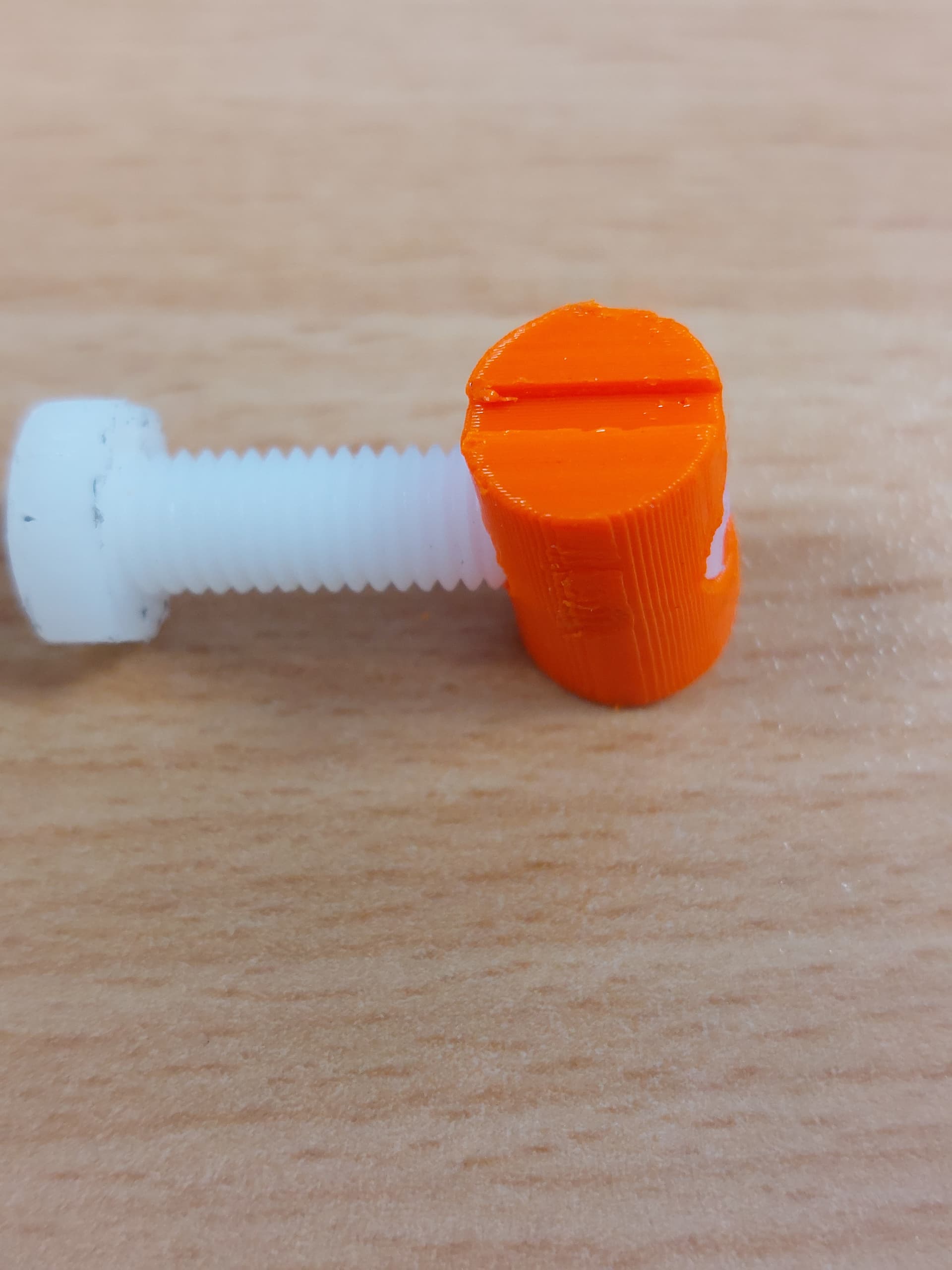
As long as the nuts are printed at the correct orientation (Length ways) they seem to be at least acceptable for sportsman style robots. We could have just put wood screws into the frame, but since we had already drilled all the holes for the barrel nuts we gave this a try. The orange printed nuts also fitted the robots design nicely.
3rd event
The 3rd event was BEVS at the North Down Orchard. Without doubt the most enjoyable event of the robot fighting year this one for me.
The Robot made the weight! That felt like the first battle was already won.
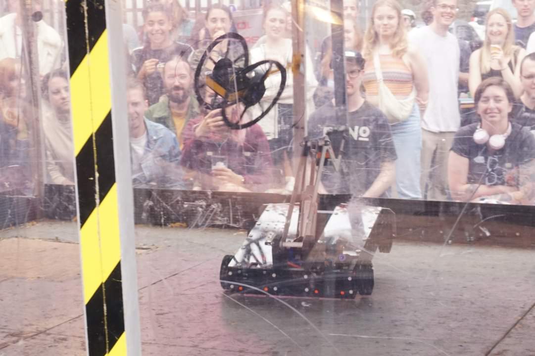
Flipperpool had a great day and finally lived up to its potential.
The upgrade to the air flow on the flipper ram worked a treat and the robot was pulling off exciting flips instead of lifts and self-righted with a backflip instead of laying there looking sad…
The whole system takes about 8 seconds to fully compress to 10 bar.
At full compression you got 3 very strong flips before you start to see a drop off.
If you flip once at full compression it takes about 3 seconds to fully compress and so it is very usable in a fight, you never run out of air and it makes an intermediating growl the whole time.
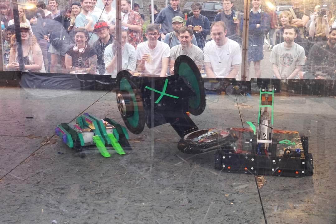
We got two wins in the main rounds including our first time flipping someone out of the arena. We only lost by judges’ decision to the overall winner (and 3 time champion) and were the only robot to take them to the judges.
Overall a lot of fun.

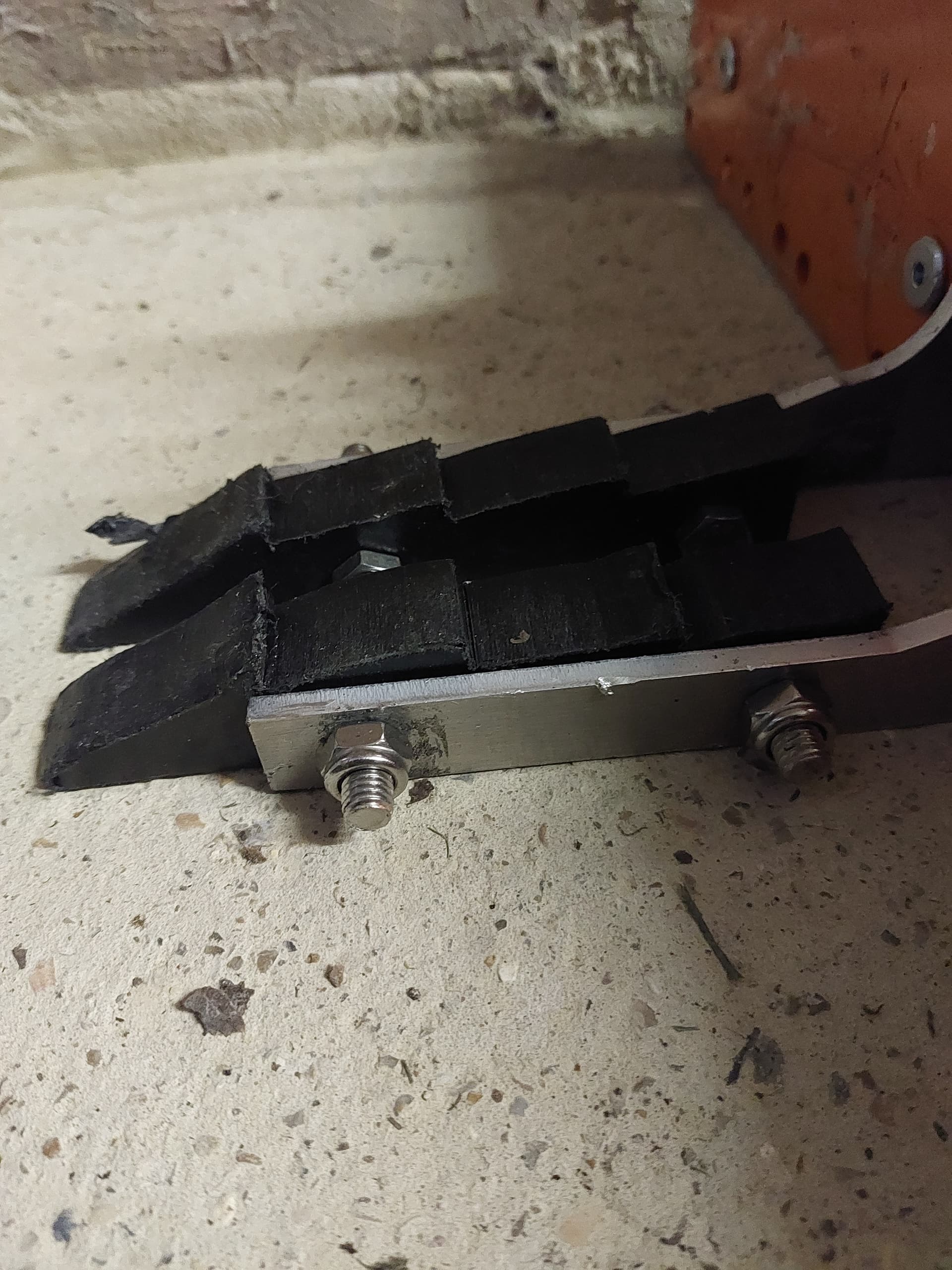
The 3d printed barrel nuts held up well, they were rock solid in all the fights. The nylon bolts were not as great as we lost a front plate during a fight when one sheered… it got a great reaction from the crowd through! Potentially going forward a combination of the 3D printed nuts but aluminium bolts might work better.
The other potential upgrade after this event could be with the ground game, we lost our fight against Terabyte because we only managed to get under them once. Terabyte is a very well designed and driven machine but perhaps a redesign of the front forks might allow us to get under them better. This could be difficult to do with the BEV rules of no metal forks, maybe some 3D printed TPU? Or additional mounted wedglets?