Been a little while since my days of posting on RW101, back when all I had were questions and some questionable design choices. In the six years since, I think the design choices are still questionable - but hopefully in a different, more interesting way. But I thought this might be a fun, less ‘formal team page post’ kind of atmosphere to share my build progress, since folk seem keen to ask whenever they see me.
Ok, so what?
For the last 8 or so months, inbetween life stuff, I’ve been working on building a new version of my 4-bar beetle Crossblow, with a weapon powered by a Blip-style flywheel.
Uhhh, Why?
A mix of boredom, hubris, and a sense that I’d really done all I wanted to with a brushed, 4wd servo lifter. Crossblow III was my most successful bot so far, and I’d gotten to a point with it where I’d resolved most of it’s flaws, at least as far as the construction and design were concerned. The chassis was getting tired, and I could either build a new version with most of the same parts and only minor tweaks, or jump head first into trying to really level it up, and hopefully teach myself new skills along the way. Doing something different is what drives me in this hobby, and I think it’s fair to say that this concept is pretty unique!
What follows is a brief, yet rambling summary of the journey so far, intended for your entertainment, and to catch you all up. Comments, criticisms and ideas welcome.
Attempt 1 - Burgh '22
I forget when the genesis of this idea came about, but probably sometime between Scouse 1 and Rapture '22. And when a badly wired borrowed ESC blew out the whole wiring loom of Crossblow 3 midway through Rapture, the course was set in my mind. I took a break from Crossblow, focused on the Barber Surgeon, and eventually got around to the CAD stage for a Crossblow successor. The first part required understanding how Blip even worked. For those not in the know, there’s a great video explainer from Battlebots here: https://fb.watch/kShQgCCTo7/, but in summary, there’s a flywheel, engaged by a clutch, that dumps it’s kinetic energy into a cord, which twists to pull a rack-and-pinion, which fires the weapon. I poured over every still frame from the Blip Reveal video on Youtube, which got most of the basics down, and a discussion with Thomas Yau about his Blip-style shuffler ant, Crash to Desktop, gave me the final pieces.
One big concern was weight. I wanted to directly scale the weight of the flywheel in Blip - 16lbs in a 250lbs robot - to beetles - 96g in a 1.5kg robot. So the decision was made to cut weight from Crossblow 3 in as many areas as possible, starting with the drive. 4 brushed 22mms became 2 brushless 1806 conversions, belted to the rear wheels with a 3d printed pulley I designed to replace the FT twist hub ring. The wheels became smaller, and I adopted a Lucky inspired silhouette to remove more material from the bot and save on weight, hoping that the new weapon would have the power to self right.
I reached out to Jeremy of Team Zanbots to machine a cone clutch in mild steel - to roughly match the 96g weight target. I deliberated on printing the ‘female’ part of the clutch to save weight/provide a grippy clutch surface, but I ultimately decided for full steel to avoid the high risk of melting the printed parts. Then I spent time diving into gear design, in hopes of trying to understand how best to create the rack-and-pinion part of the weapon. I focused on the wiring, opting for two 2s batteries split across the each side of the robot to be more economical with space. I even selected a UHMW-based fishing line for the twist cord. Things were starting to come together.
Then Uni got insanely busy and 'Burgh crept up. I wasn’t able to get my plastic machined where I usually would. I wasn’t able to get the weapon motor I wanted and had to opt for something of similar dimensions (but a completely inappropriate Kv) to save me redesigning the whole robot. Huge shout-out to Scott Anderson, by the way. Together we cut the chassis out by hand, and made as tidy a job of it as anyone could. But I’d made several design decisions that presupposed that the chassis would be cut on a CNC machine, and it’s a miracle we even got it close to working. Ultimately, I ran out of time to complete even a compromised version of my vision, and probably took on too much. The robot was unable to make it into the arena and I began the long and laborious process of trying to improve everything that I had just rushed together.
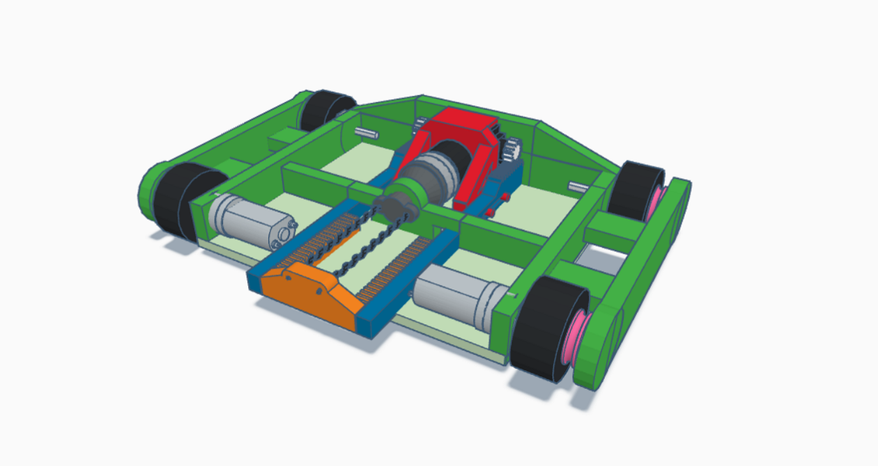
An early version of the Crossblow IV CAD
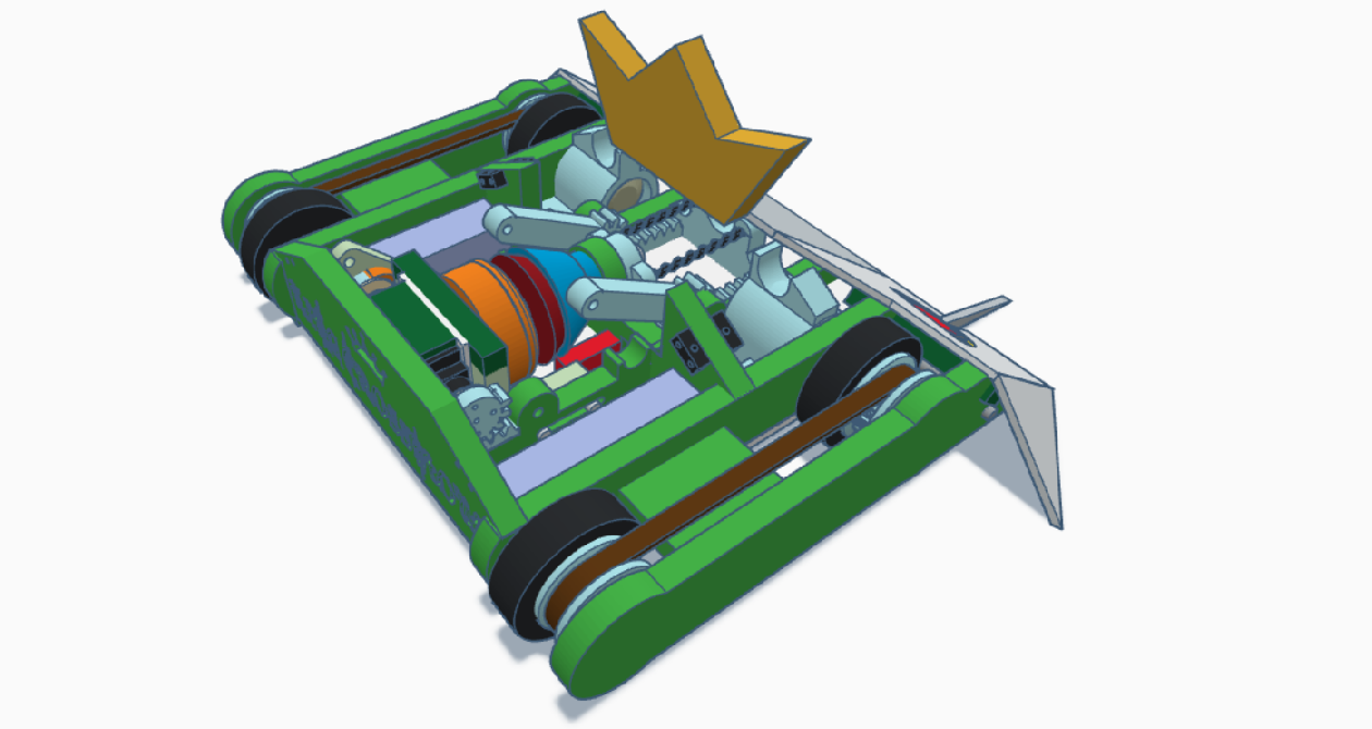
The final design for the compromised King Crossblow built for Battle in the Burgh
Attempt 2 - Ongoing
I wanted to redesign almost every part of the weapon. The motor was the easiest change to make, and I selected a 2826 outrunner by Overlander, partly due to it’s small form and availability, but more importantly, it’s high Kv rating. According to the spreadsheets shown in the Blip Reveal video, it’s weapon motor runs at ≈24,000rpm unloaded, and at about half that with the weight of the flywheel. The 1900Kv motor I had sourced ran a bit higher - at around 28,000rpm unloaded, but it seemed to be the best compromise I could make. The ESC is a Spedix 35A running BL_Heli32, which should allow me to fine tune the ESC with BL_Heli suite and the mini arduino provided to me by Ben Hay.
Next on the chopping block was the clutch engagement. The Burgh spec design used 2 antweight servos on a mini rack-and-pinion to engage the weapon, and I’d designed some simple runners to be CNC’d into the robot to keep it in place. Unfortunately, I was unable to execute that by hand, and at Burgh it was just held in place by some loose shoulder bolts in some short slots. I started by CADding and printing some interlocking pieces to create linear slides, having looked into pre-made slides, complete with bearings, and being unable to find something with the right form factor. With a little silicon grease, they seemed to work well, but I wanted a more elegant solution to power it, and settled on linear solenoids.
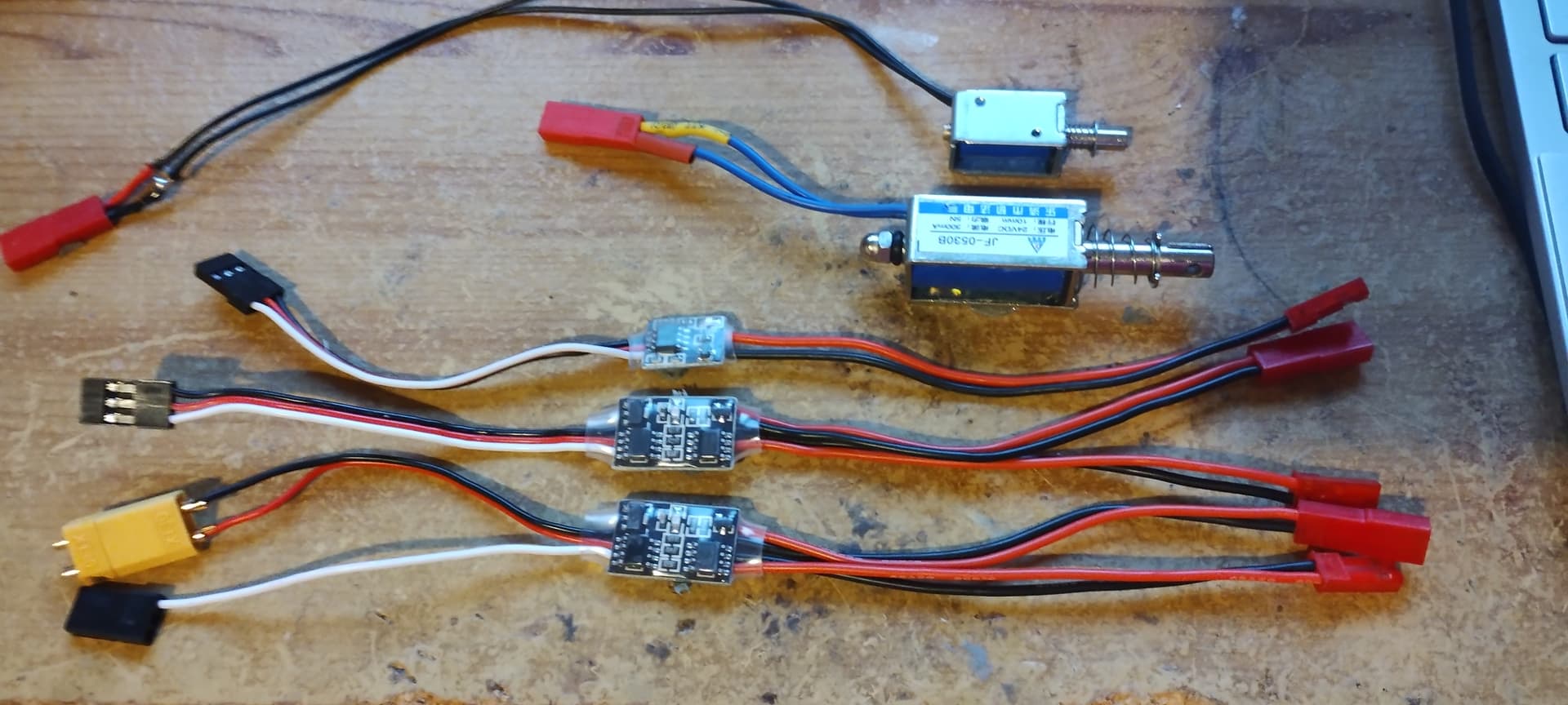
These too, have proven to have their own challenges. The first set I bought had very weedy return springs that were unable to disengage the clutch at all. I bought some stronger springs and swapped them in, but they were then too strong for the solenoid to engage at all. Small spring sellers online seem to provide frustratingly few details on the spring’s force rating! I’ve now moved on to some larger solenoids provided by David Harrison, which look like they will perform better, but I’m waiting on a new control board for them before I can do a real test. I did, however, have to move away from the linear slide concept, since it simply created too much friction for the springs to disengage the clutch again, but fortunately, these solenoids have enough mounting points that I can mount the whole clutch ‘floating’ in a purpose printed cradle. The solenoids I’m using currently are the JF-0530B’s. There’s a chance that these too, won’t be up to the task, in which case, I’ll return to the servos and the mini rack-and-pinion, this time mated to a printed linear slide, to see if that will produce the desired results.
Meantime King Crossblow did make it to an event, albeit with a servo powered weapon. Some of you may have seen, but it drove just fine the night before, but died on the testbench on the day of the event, with the cause suspected to be broken stator wires within the drive motors. Frustrating. But new motors have been prepared, and a new chassis is planned, if not yet designed.
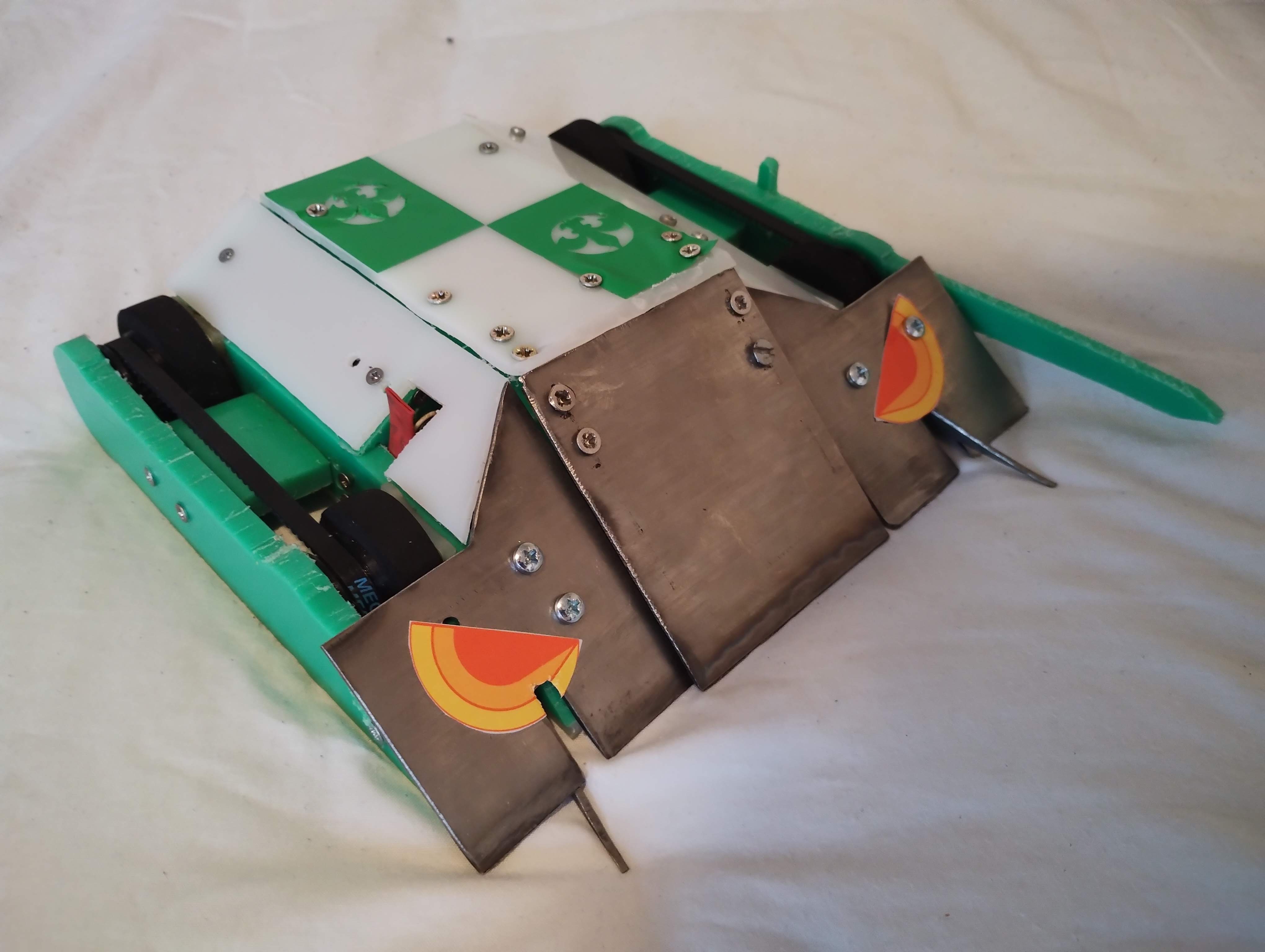
King Crossblow, still working, a few days prior to Scouse Showdown 2
Lastly, I’m experimenting with clutch linings. It wasn’t something I could find much details on online, so for now I’m trialling some massive heatshrink! Next up for me is to test the clutch changes, and redesign the rack-and-pinion section to use herringbone gears. I noticed from the Burgh prototype that simple spur gears didn’t have enough contact area to move the four bar smoothly, so I felt I wanted to increase it to increase the transfer of torque and to more smoothly. This requires me to improve my skills in Fusion360, which is going well! A combination of guides, friends’ advice, and chatGPT is setting me on a path to much better CAD skills, which should stand me in good stead going forward.
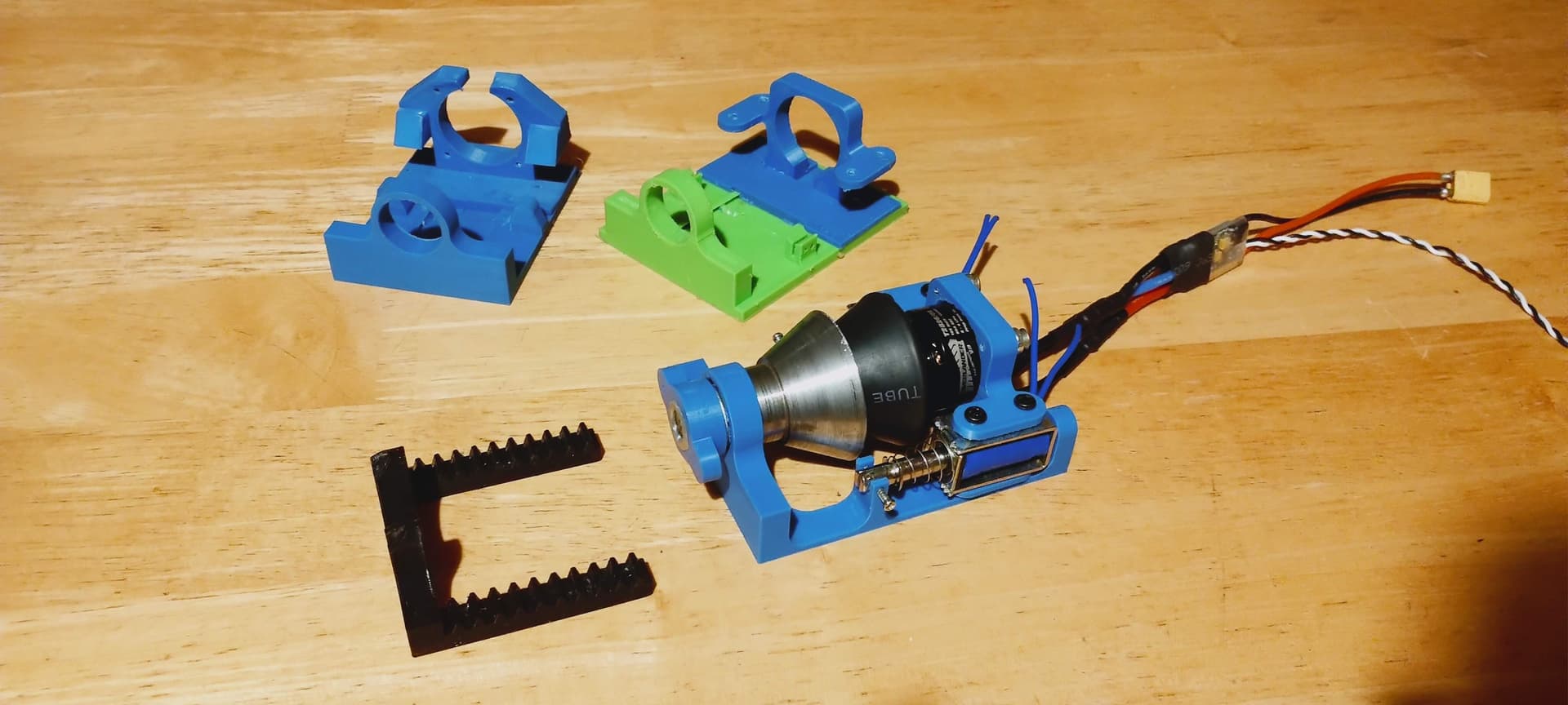
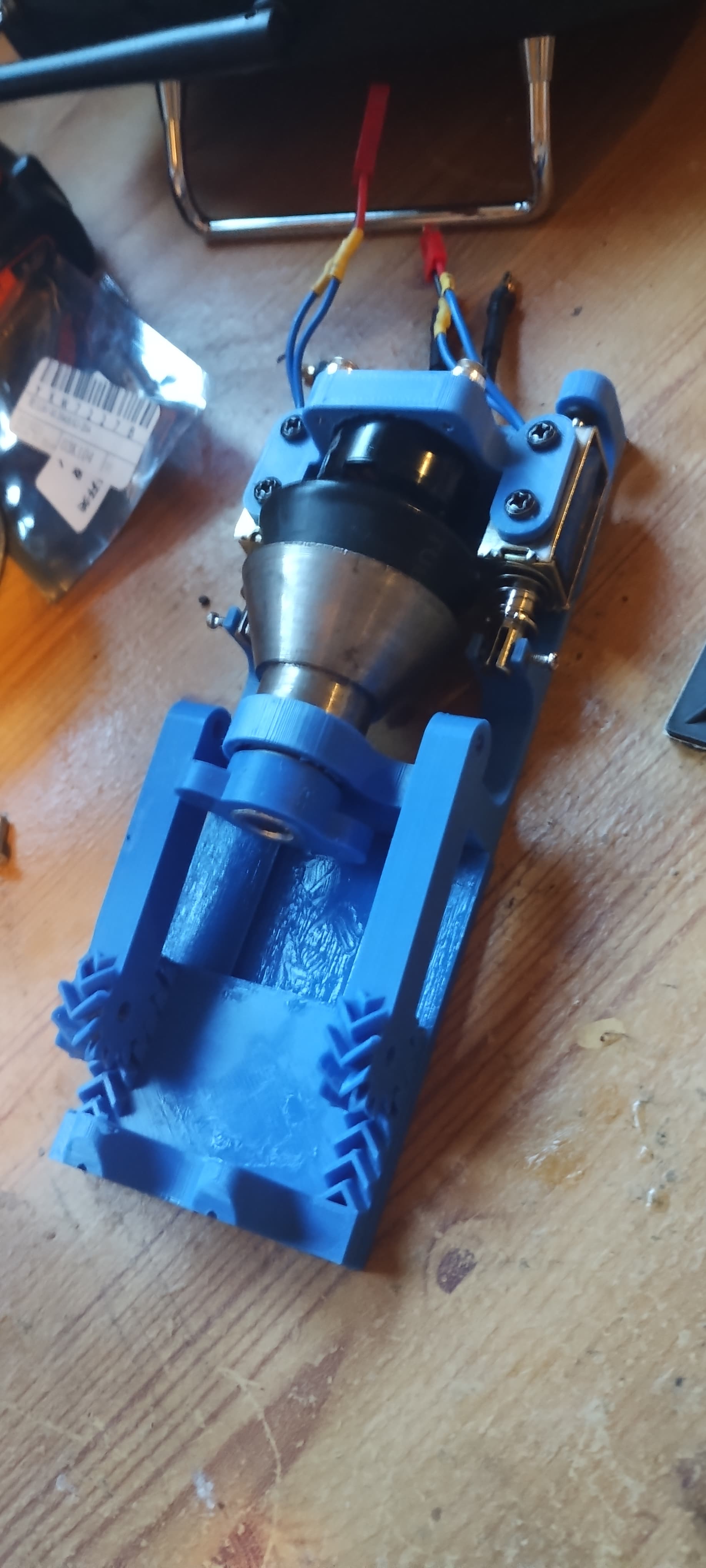
The current iteration of the ‘floating’ clutch, along with a couple of previous revisions that used the linear slide
That brings us to present-day. I’ve had other focuses - Lego Wars robots, ants, and personal things, but this is my priority now! My schedule is such that I don’t have any big beetle events planned until much later in the year, so I’ve got plenty of time to try and make this work. All going well, I hope to have a full prototype of the weapon running in a couple of weeks time! I hope this has been an enjoyable read. If nothing else, I’ve learned a lot and grown as a builder throughout this process so far, and I’m crossing my fingers that it will all pay off. I’m not an engineer, I’m a humanities student, and, as the title says, I feel like I’m building heavily on the work of others, some with a better understanding of the maths, some offering help where they can to bring this mad idea into being. I just want to say a massive thank you to anyone and everyone who has been involved in this project so far for everything you’ve contributed. I’ll answer what questions I can, update this thread as I make progress, and I look forward to taking on any advice you all may have to optimise this further. Thank you for reading this far, if you have. It’s not quite War and Peace, but getting on that way!
I’m wrapping up. Until the next one!