Typical Soldering Operations
XT60, XT30, and MR30 connectors
Probably the most common connectors in combat robotics are the XT60, XT30, and MR30 - XT30s and MR30s use the same pins, but the MR30s have three of them. They’re pretty great, and far easier to solder than the old Deans plugs from RC car racing back in the day (OGs will remember, and probably still have T shaped burns on their fingers, also and lots of slightly melted connectors that don’t quite fit together in a box somewhere). They all use the same solder-bucket style pins, but since XT60s are a lot larger and easier to see I’ll start with them.
I’ll also add that a lot of this is stream of consciousness, so it’s best to read through the whole thing before focusing on specific sections, as later sections may assume that you’ve read previous ones!
XT60
Your first step is to find a mating half for the connector you want to solder. While they’re pretty heat resistant they are thermoplastic, so you can melt them, and the brass connector pins will wander off, leaving you with a connector that doesn’t plug into anything. A mating half keeps it all indexed if things get a bit melty.
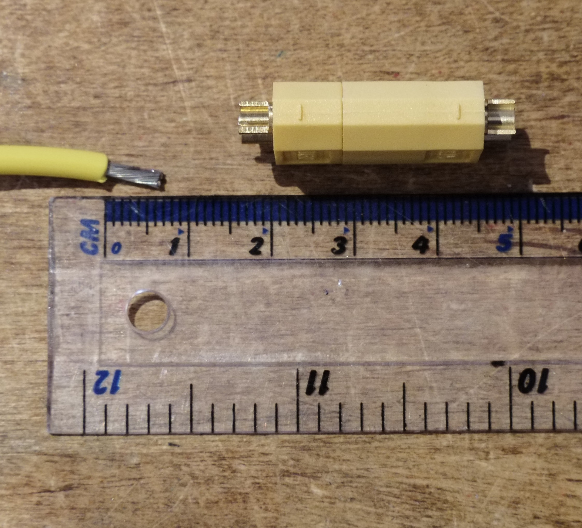
Next, strip the wire. For an XT60 and with wire sizes up to AWG14 or so you want the exposed copper strands to be about 6mm long, which is roughly the depth of the solder bucket. You can make AWG12 work, but it might not fit all the way inside the solder bucket - if this is the case you’ll want to only strip about 3-4mm so that it sits inside only the open section of the solder bucket. Twist the strands together a few times with your fingers so they stay together. It should look like this:
Next you’ll want to tin the wires. Don’t forget the general steps of cleaning and tinning the iron.

(Animated clip, open in new tab if it doesn’t move for you)
You can see how easily the fresh solder flows from the iron into the wire. The fumes coming off the iron is the flux - this is good, and an indicator that there’s flux on the iron. If the smoke stops, the iron needs more solder (and the flux that comes with it). You’ll also notice I’m trying to feed the solder into the wire, rather than onto the iron. Solder flows towards heat, and will wick onto copper wires and connectors if they’re hot enough, so you’re trying to get it to soak into the wire with all the flux it contains, in preference to sitting on the iron burning off the flux as you try in vain to get a blob to soak in.
When tinning wires you ideally want to keep the solder to the exposed portion of the wire. If it enters under the insulation you can end up with a hard section of wire that produces a single point of strain. You’re also trying to do it quickly enough not to melt any insulation, but thankfully we mostly use silicone insulated wires for combat robotics, and these don’t melt like PVC insulated wire does.
Next you want to tin the solder bucket on the XT60. Ideally you want the solder coating the whole inside surface, with the surface tension holding it in a nice dished convex meniscus. For whatever reason this isn’t always possible with XT60s, as it doesn’t quite like to stick to the top surface of the solder bucket, but you can usually get pretty close:

(Animated clip, open in new tab if it doesn’t move for you)
Now that both sides are tinned, you can easily reflow the two sides together in one operation. You’ll want to do this quickly while there’s still flux on the iron, but if it’s a little crusty afterwards (like my joint, as I took my time trying not to knock the camera over) then a little dab of fresh solder once the joint is soldered will work wonders.
Also, unless the other ends of the wires are still bare, this is the time to slide heatshrink over them, but you will forget occasionally. I’ve been doing this kind of thing for years and I still forget every now and again and have to desolder and wait for everything to cool before starting again…

(Animated clip, open in new tab if it doesn’t move for you)
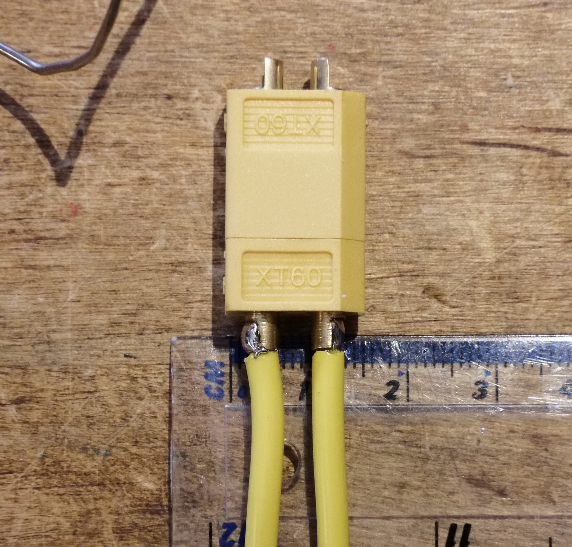
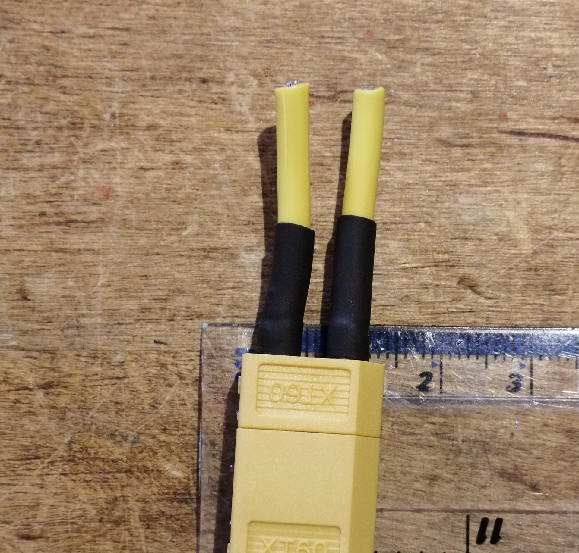
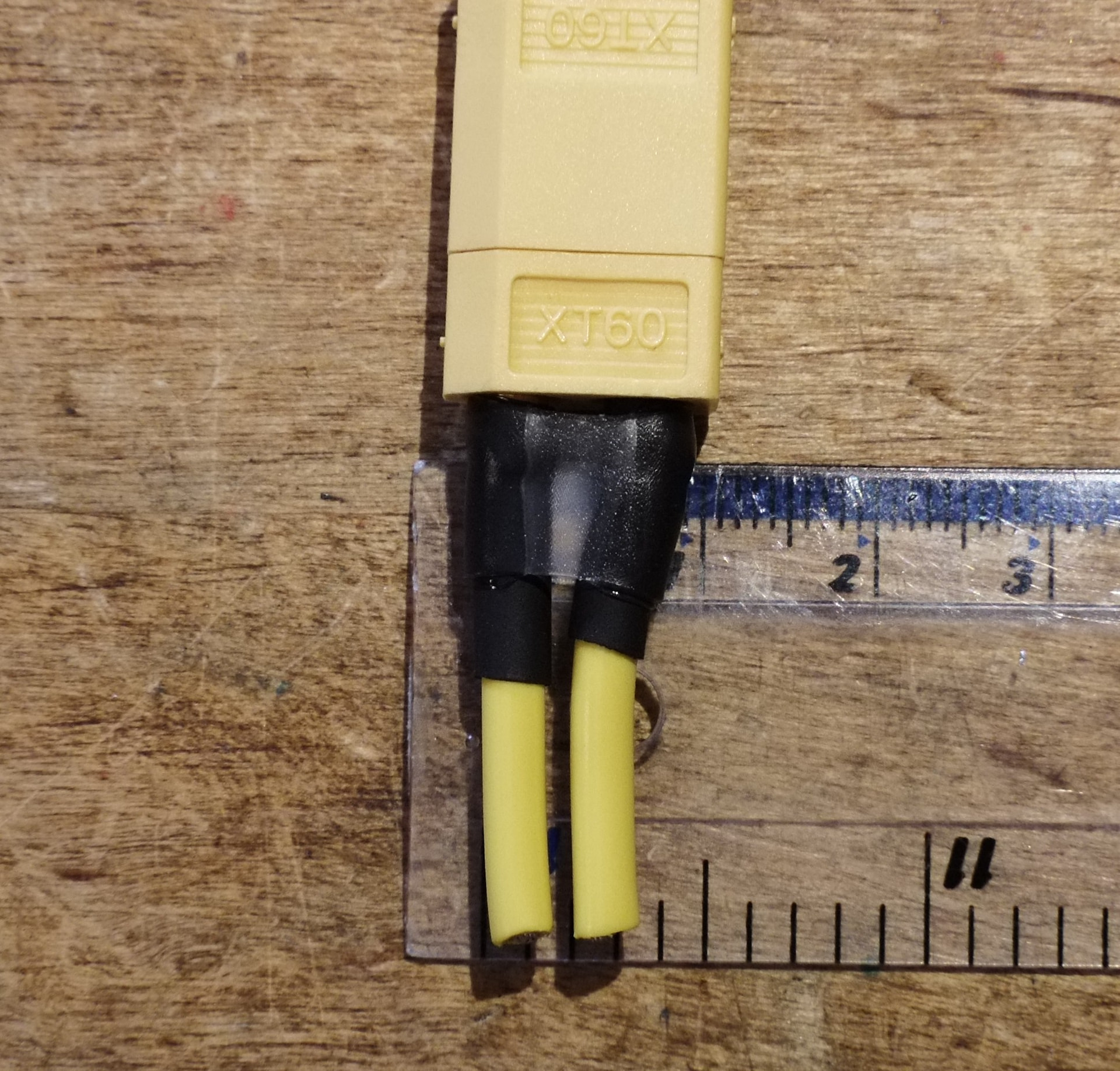
You should now have some relatively neat solder joints, and once they’re cool you can slide the heatshrink over. If you’re impatient (like I sometimes am) and don’t wait the heatshrink will shrink onto the wire before it’s all the way over the pins, and you’ll be forced to desolder and fit a fresh piece. If you’re worried about the wires being tugged around, a second layer of heatshrink that holds both wires together is a good idea. I like the glue lined stuff for this use, as it has more structure and doesn’t slide around.
XT30/MR30
The process for an XT30 or MR30 is much the same, just smaller. You’ll want maybe 4-5mm of tinned wire up to AWG18, and 3-4mm for AWG16.
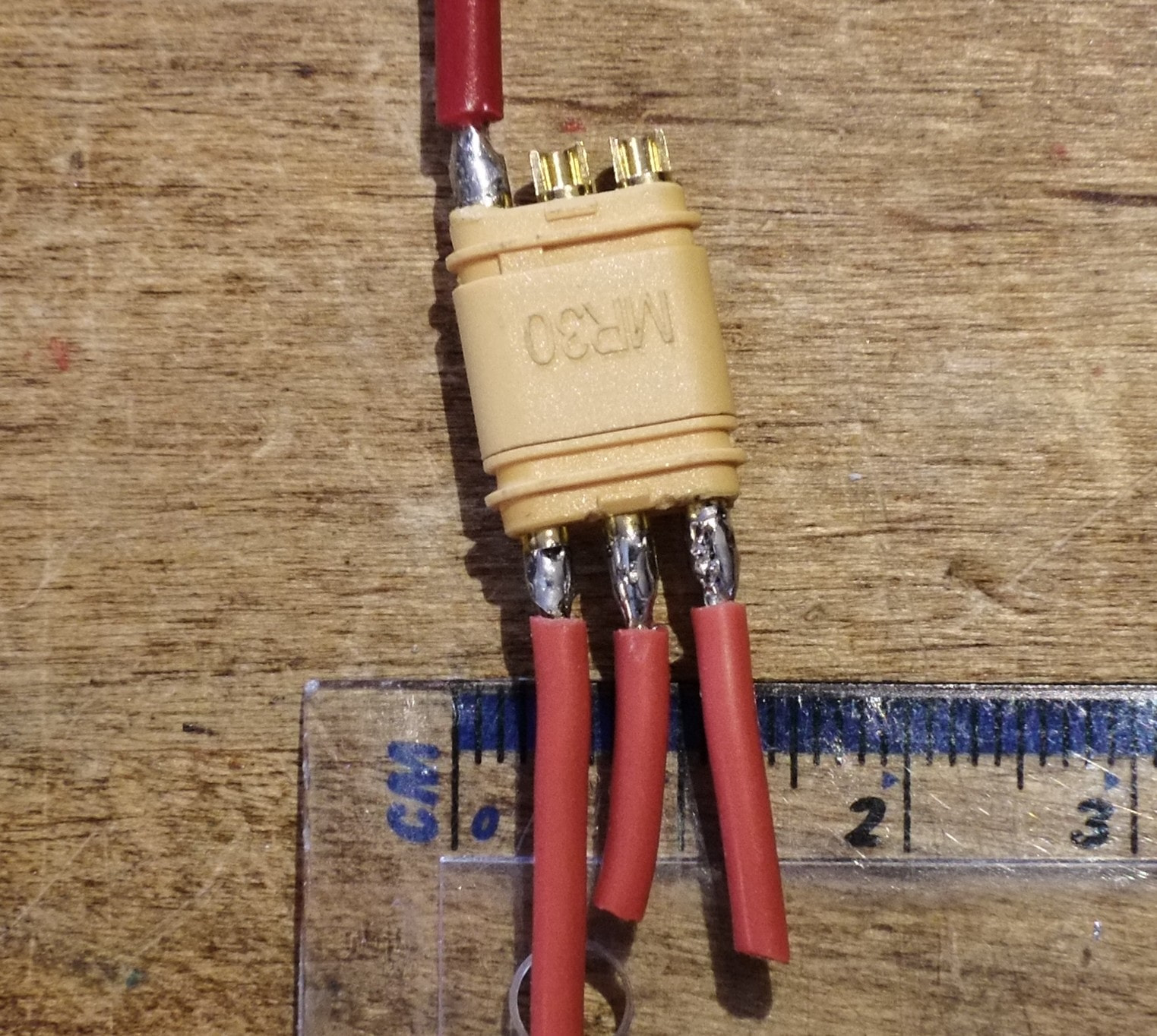
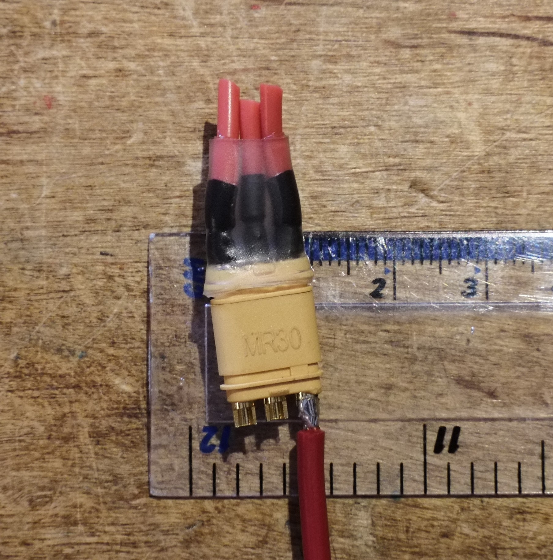
While MR30s come with a little plastic cover for the pins, it doesn’t fit over heatshrink on larger wire sizes, so I prefer to use heatshrink as the plastic cover can come off and expose the bare solder joints. Like the XT60 you can use glue-lined heatshrink for some extra strain relief on the wires, but for the smaller connectors you’re able to slide it over the connector body as well as the wires and pins:
Wire Splicing
Whether it be an “oops too short” moment, or a broken wire during a fight, or you need somewhere to connect a power LED, you’ll probably need to join two wires together. You’ll often see people just stick two tinned wires next to each other and melting the solder together (lap joint), sometimes with some tape to hold them together, or those crocodile clip “Helping hands” stands, or sometimes a friend with asbestos fingers. This works if you’re in a rush but it kind of sucks. Solder is a really bad mechanical connection, and often the two lap jointed wires don’t sit parallel, meaning the entire joint is held together with a little tiny connecting blob of solder. There are better options!
*Lap joints are covered in IPC7711, but crucially they require a piece of very thin single core wire to be wound round the joint before soldering. Not really practical at a pit table.
Hook Splice
Also known as the Western Union splice from back when Western Union ran telegraph wires across the US. Crucially for this splice, the wires themselves provide the mechanical connection, and the solder exists just to stop any minor movement and to provide good electrical conductivity.
While it works better for single core wires, and can end up a little messy with stranded wires, this is the best option if you’re doing wiring at home before an event. It’s absolutely the strongest, as the resulting joint will be stronger than the wire itself. The downside is you need to strip a lot of insulation for it to work correctly, so it’s not so great for emergency repairs where you might not have much wire length.
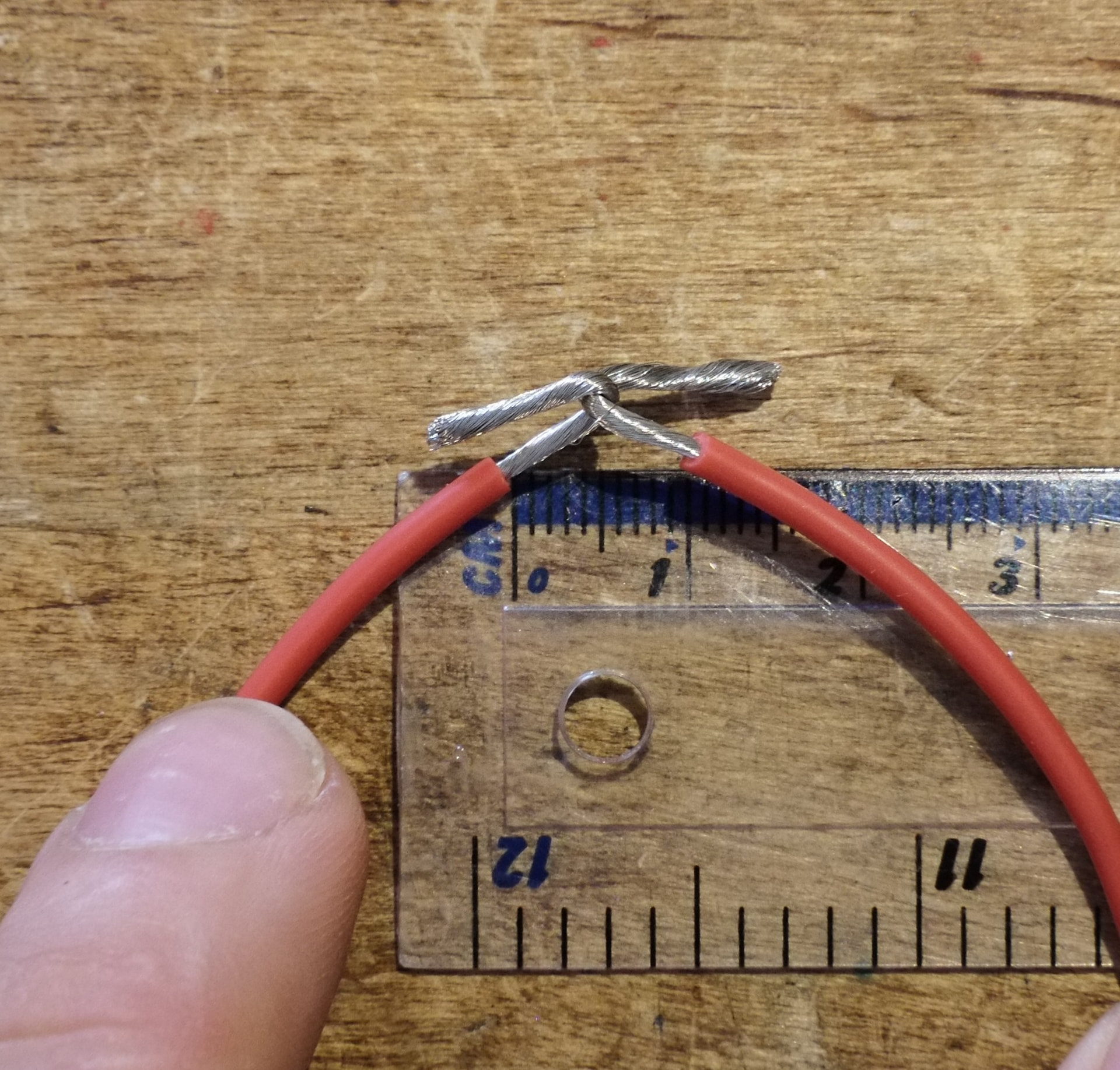
First, you want to strip about 20mm of wire from each end, and twist it together tightly. Then, put a 90 degree bend in each and interlock them:
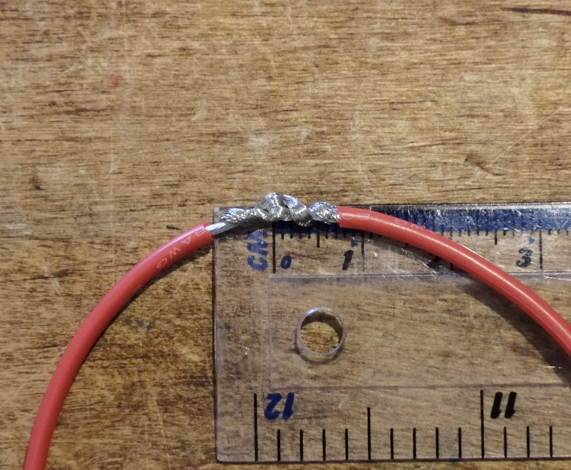
Then, take each wire and wrap it around itself. The spec says three times, which is achievable for something like a 24awg receiver or power light wire, but for this 20AWG wire a single wrap is good enough. You’ll want to make sure the loose wire ends are all tucked away neatly, as they become tiny little heatshrink-slicing knife blades when soldered otherwise:
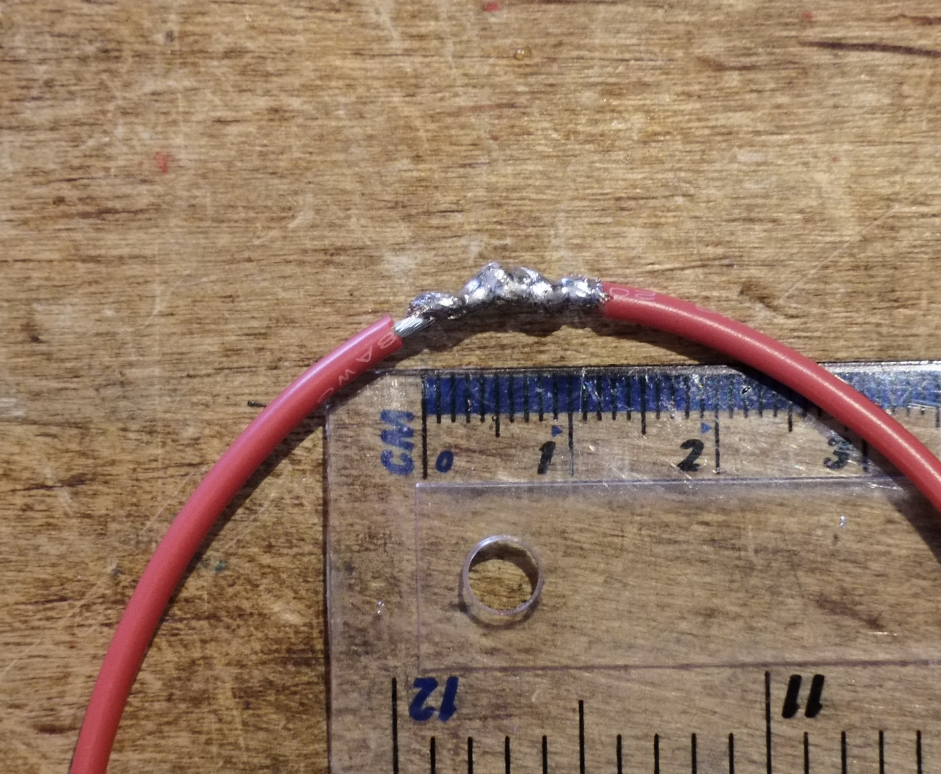
Then, solder it. It will take more solder than you expect, so check both sides of the joint to make sure the solder has wicked all the way through.
Finally, heatshrink it - you should make the heathshrink about three times longer than the joint so it has a decent overlap with the joint on either side. You did slide heatshrink over the wire first, right? Right?
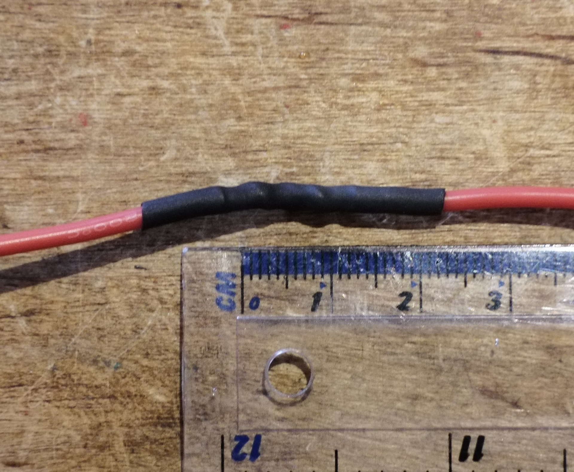
Mesh Splice
This is my preferred option for emergency repairs. It needs less spare length than a hook splice, and fewer hands than a caveman-style lap splice (the average number of hands required for this is about three and a half), while also being far stronger than the lap splice due to the sheer surface area contact that the solder has to grab.
First, strip about 5-10mm of wire. Don’t twist it! Instead, push the ends together so the strands are interlocked, and carefully roll it back and forth between your fingers. The friction between strands will keep it together:
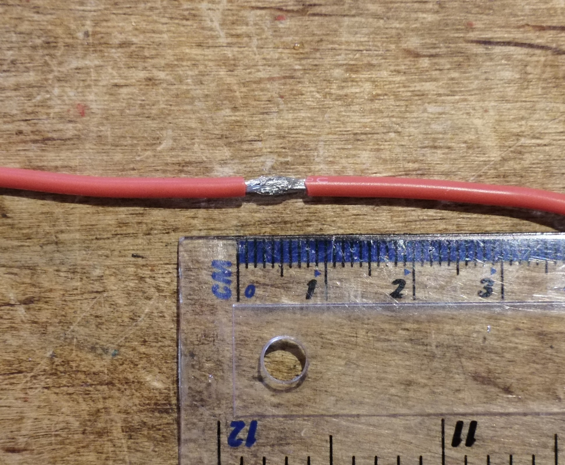
Then solder as below and heatshrink, following the same 3x joint length heatshrink rule as the Hook splice.
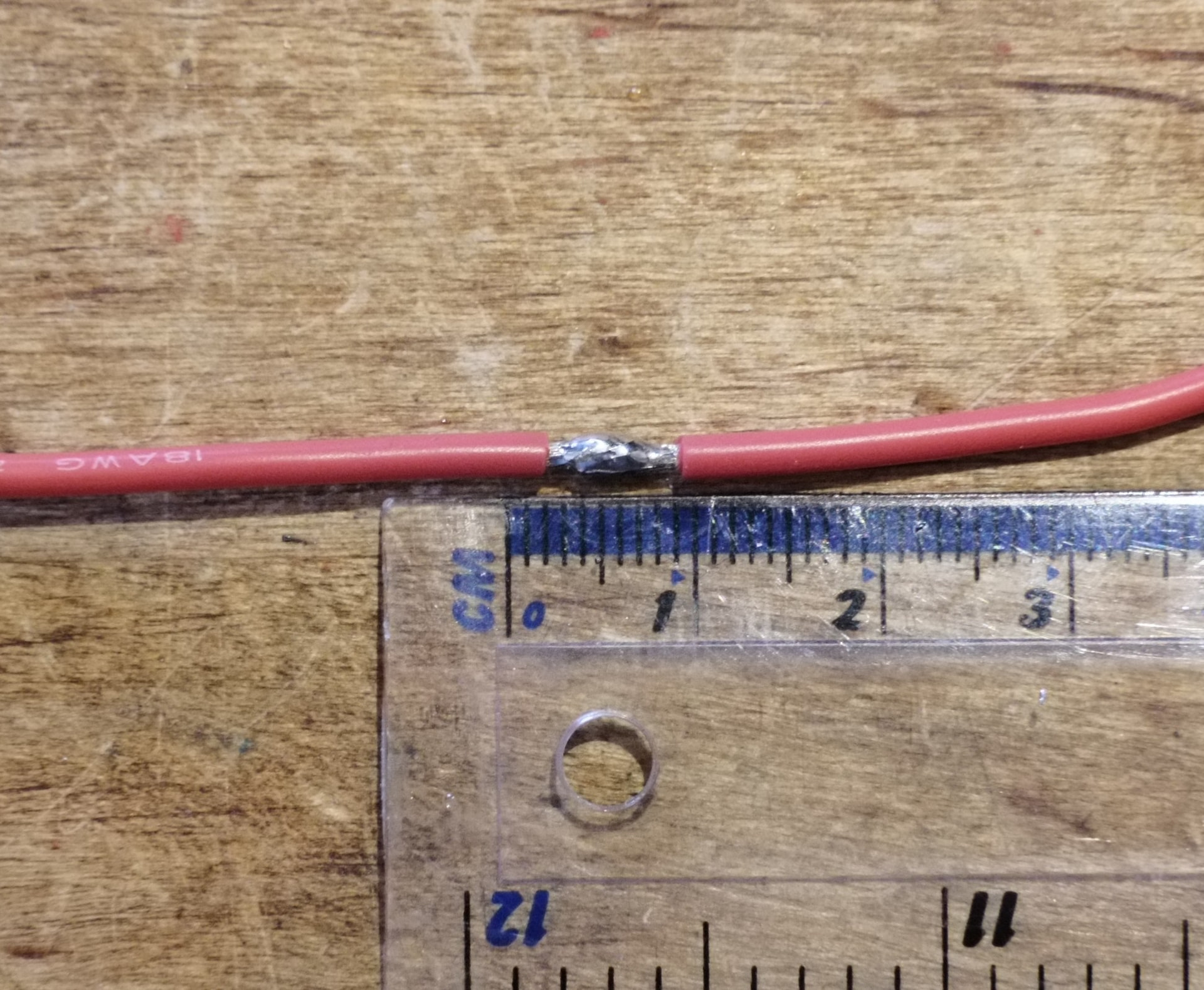
Three Way Splice
Sometimes you need to split a wire two ways. This works best with a smaller wire (ideal for a power light) as the third, but if you’re careful and don’t mind a lumpy splice then you can do it with equal-sized wires.
You’ll want to follow the same process as the hook splice, but before soldering you take the third wire and wrap it around, ideally 3-4 times for a smaller wire, but do your best with a larger wire - it can help to have some extra insulation on one end in these cases, as you can wrap round that rather than the main splice:
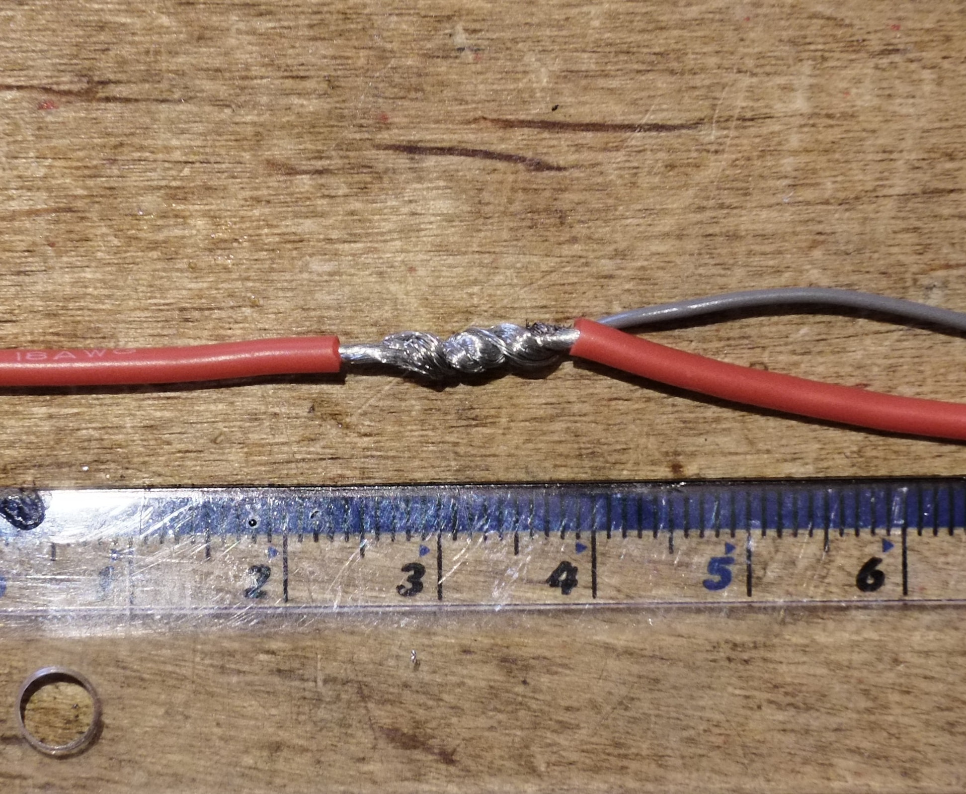
(RIP my ruler)
>3 Way Splices
You might be able to get a four way splice going if you mirror the three way. For any more than four wires, may I introduce you to our lord and saviour the Wago Connector? They are the only thing preventing The Luggage (and a few other bots - I know Forkhead uses Wagos) becoming total spaghetti inside.
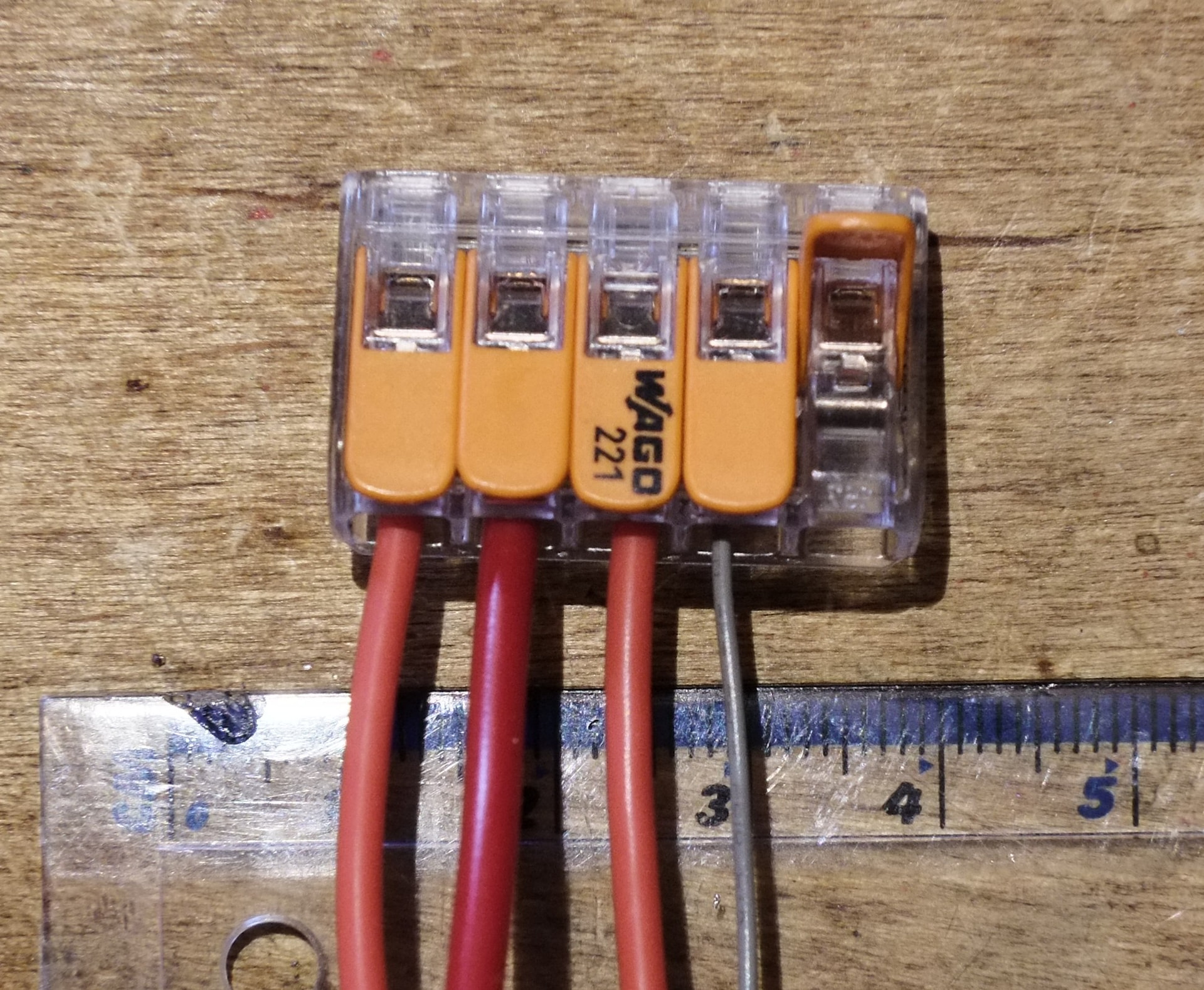
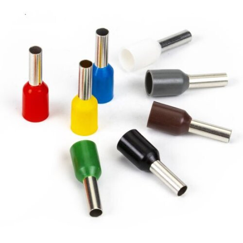
If you’re feeling extra you can use bootlace ferrules to hold the wire strands together and provide strain relief, but wagos work pretty well without them.
PCB Solder pads
SMD (surface mount) and TH (through hole) pads are probably the highest risk connections in a robot. There’s no easy way to strain relieve them like there is with an XT series connector, so they’re liable to flex and crack where the insulation ends, and especially for SMD pads you risk pulling a pad off a board entirely. Thankfully there are a few solutions!
SMD Pads
You’ll usually find these on ESCs. For this example I’m using an Emax Bullet 12A as found in Ultimate Ninja and Birdemic, but the process is the same for beetleweight and larger ESCs with the same pads. This technique also works if you want to run wires off a TH pad parallel to the board for packaging reasons - just ignore the hole and treat the top or bottom of the TH pad as an SMD pad.
First you want to tin the pads. If the ESC came pre-soldered it likely came with lead-free solder. If you’re using leaded solder you’ll want to remove as much of the old solder as possible with a solder sucker or solder flux, add fresh solder, and maybe repeat the process a few times until the solder on the pads cools to a smooth shiny blob. Lead/lead-free solder alloys do weird stuff, but thankfully they let you know what’s going on by looking like absolute trash.
To get a consistent amount of solder on each pad you can lean on the surface tension of a good, well fluxed solder blob, and the tendency of solder to move to areas of lower concentration. If there’s not enough solder on the pads or they look blobby and crusty, put more iron on the solder (and maybe some flux on the board) and drag it around a bit. If there’s too much, clean the iron and dab it at the pads and it’ll suck any excess back onto the iron, where you can wipe it off in your tip cleaner.
You’ll notice I remove the iron away from the pads very quickly. If you linger on the pads too long you can burn the flux off, and when you remove the iron slowly it leaves a little point or tail behind. Moving quickly lets the solder flow back into a nice smooth blob before it cools. Don’t stay on the pads too long or you’ll risk lifting them off the board.

(Animated clip, open in new tab if it doesn’t move for you)
Next you’ll want to strip your wire to about the same length as the pad, and then tin it. You stick them together the same way you stick a wire into an XT - by melting the solder on the pad and jabbing the wire into it, giving it a second for the temperature to equalise, and removing it.
If some of the joints look a little crusty that’s fine, what can help there is to get all the wires stuck down in the correct position, then tape them/weight them down to your workbench to keep them stationary. It’s then a lot easier to come in with the iron and some fresh solder and/or flux and reflow them to be prettier and more secure.

(Animated clip, open in new tab if it doesn’t move for you)
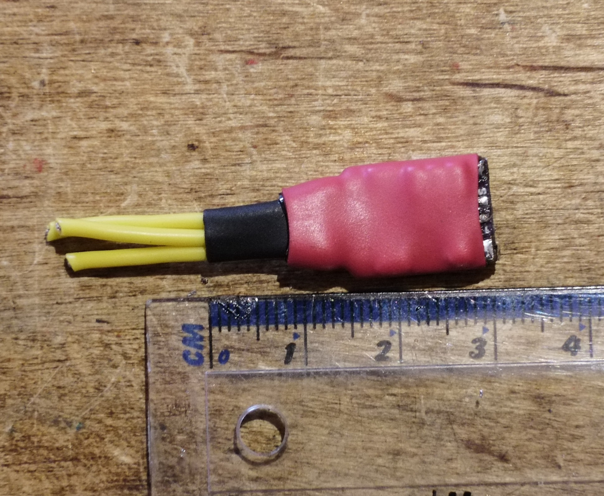
To aid in strain relief it can be helpful to angle the wires (rather than have them all exit parallel) so that they converge and run away from the board closer together. This lets you slide some heatshrink around them to bind them all together.
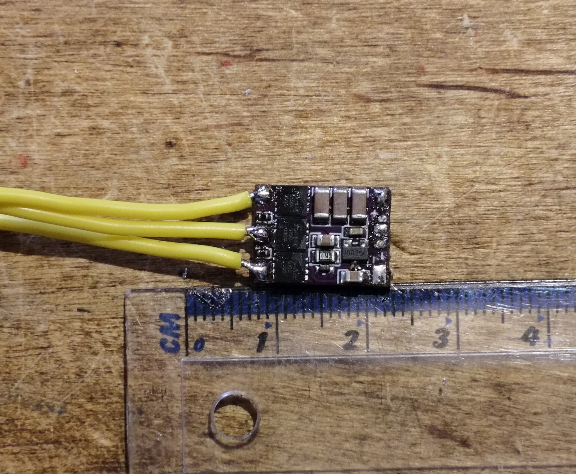
You can then overlap the heatshrink that covers the ESC with the heatshrink that covers the wires, so that any flex is induced in the floppy silicone wires rather than near the solder joints. Again, this is glue-lined, but the glue lined stuff can be too bulky or heavy for compact, min-maxed antweights so YMMV here - kapton tape works too.
TH Pads
For soldering wires to TH pads you’ll want to strip your wires to about 5mm length, twist them tightly, and tin them. Then, pass them through the board, and give them a little dab of solder - less is more. If you couldn’t tell, I’ve just been reaching for the closest suitable parts to demo these processes, so this random Adafruit ADC board that is totally unrelated to robots was just the first thing I found in my box of dev boards.

(Animated clip, open in new tab if it doesn’t move for you)
Ideally you should have a nice little Mount Fuji shaped joint on the bottom side of the board:
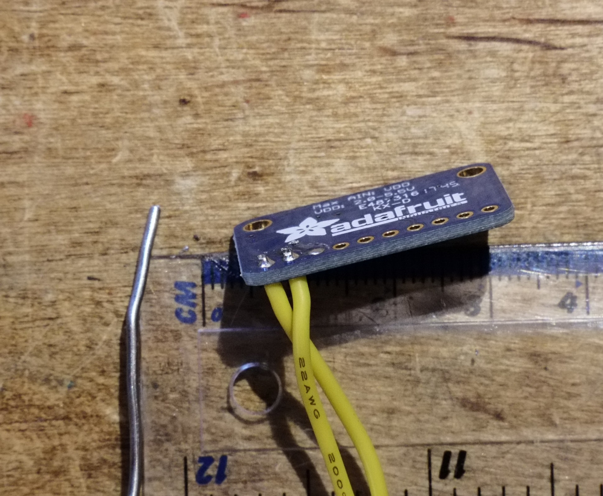
If it’s gone a little Mr Blobby, just clean your iron and come in with some flux or fresh solder. The joint will flow itself back into shape without much drama:

(Animated clip, open in new tab if it doesn’t move for you)
While TH pads are much less likely to rip off the board than SMD pads, you don’t get the benefit of being able to wrap the whole board in heatshrink to constrain the wires. You can however bundle wires together in twos or threes, which moves the majority of flex away from the board and into where the wires diverge:
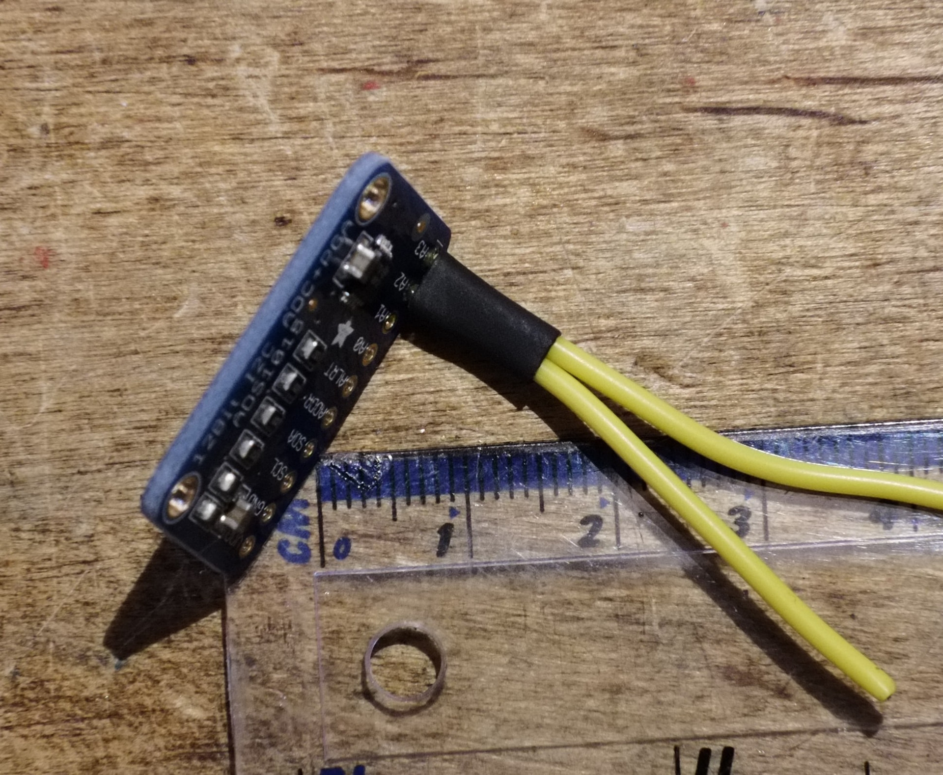
Solder Tags
Brushed motors and switches often have little solder tag connections. They sometimes have holes, but not always, so here we just have to do our best. Otherwise, the process is very similar to soldering to SMD or TH pads, depending on if your solder tags have holes in or not. Strip your wires to about the seme length as the pads and tin them. If the tags don’t have holes, or if the holes are too small, tin them too. Note that after I took this photo I noticed the tags were bent outwards, and bent them a little straighter to help with wire routing.
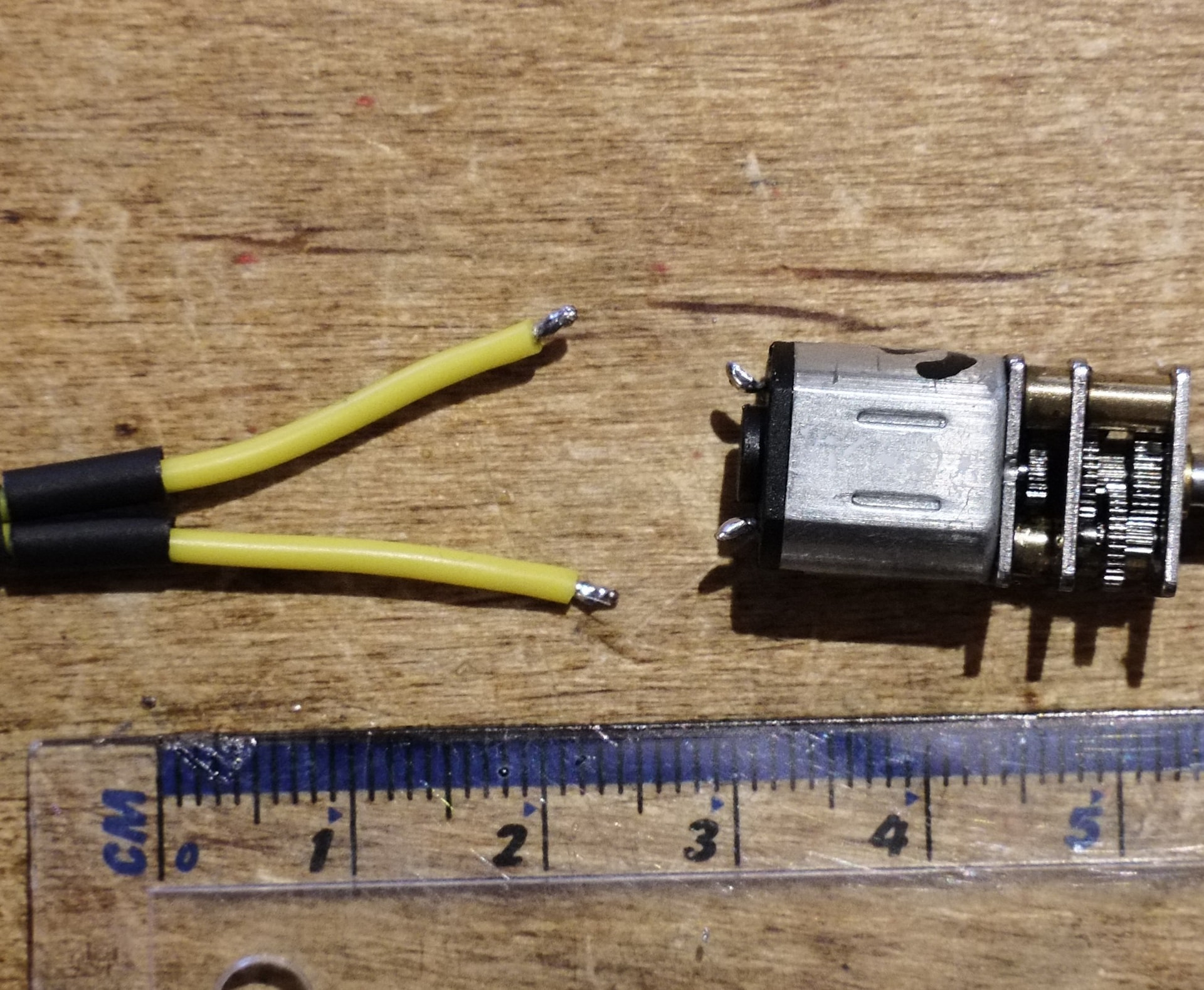
Solder the joints. If you’re not using the tag holes, reflow the two sides together, otherwise you’re applying solder to the tag like it’s a TH pad:

(Animated clip, open in new tab if it doesn’t move for you)
You should have some nice smooth joints, with wires that exit in line to the tag. These joints are a little crunchy and needed a dab more of fresh solder:
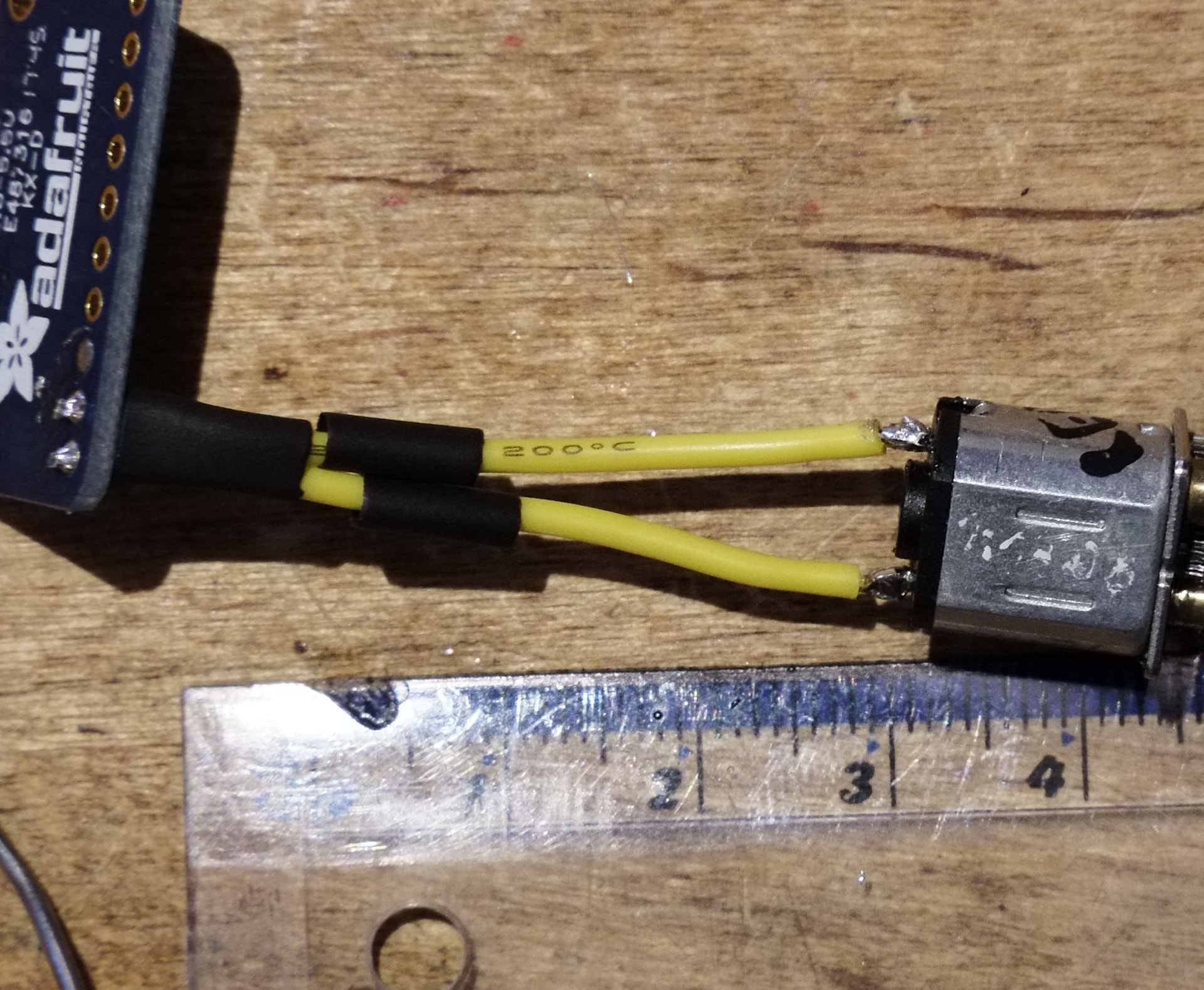
Apply the heatshrink you thoughtfully applied before soldering the wires.
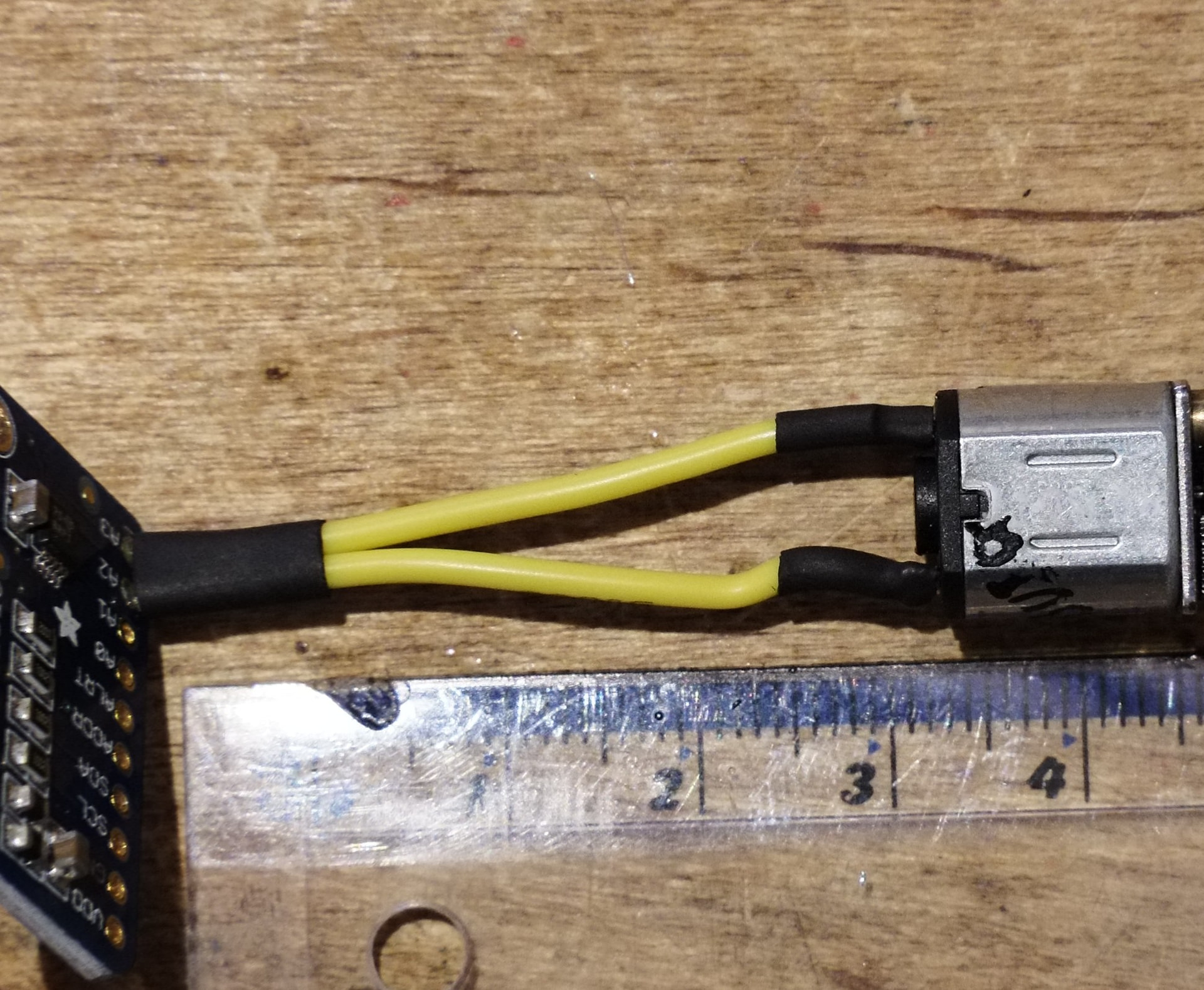
The End
I think that’s all the basics I wanted to cover! The real TL;DR here is that if you keep your iron clean, use flux, let the heat and the flux and the solder do their thing, and (this was the big one for me personally when learning) are OK with telling yourself “no that’s fugly, I need to do it again and do it right” you can go a long way towards reducing solder joints as a point of failure in your robot. I’m not going to say you’ll never lose a fight due to bad soldering, because robots are chaos, but you can remove as much risk as possible. I can confidently say I’ve never had an issue with robot wiring inside the arena, only while being a doofus at the pit table and yanking on stuff.
I photographed, videos, and wrote this all in one day, so I should probably go do literally anything else right now. Thank you for reading what has become an unexpected epic. As I think I’ve said already, please let me know if you think I should cover anything else and I’ll do my best to accommodate!