Hello everyone! In my time at various events round the country I have seen many many robots, and while everyone is super cool and so are your robots, good lord I have seen some crimes against electronics. Not only can bad soldering look nasty and really stand out against an otherwise top tier build, it really sucks to short a couple of pads and blow up a speed controller, or lose a fight due to a broken solder joint. A little while ago I decided to put this guide together as a quick reference on how to solder some of the common joints and connectors you’ll find inside a robot, which is not really something that most generic soldering guides (like the excellent Adafruit guide) explicitly cover.
First, some background on myself and my experience with soldering. When I was about 10 my Hornby train set broke, and rather than fixing it himself, my dad (who himself started his career with a brief stint as an R&D tech for an aerospace company) thrust a soldering iron into my hand and taught me the basics. I’m 33 now, so I’ve been inhaling lead fumes for over 20 years at this point. I also persuaded my previous employer to send me on an IPC-7711 course, which is the industry standard soldering/assembly/rework course, and between myself and a colleague we ended up teaching the basics of through hole and surface mount soldering to many of the undergraduate/intern/junior engineers that came through our lab. Many of them insisted that for various reasons they were terrible at soldering and would always be terrible, but as a rule we’d have them sticking down millimetre scale components under a microscope within a couple of hours.
The result of all this is that I’d like to think I have a pretty good understanding of the things that beginners need to know, and how to explain it in terms that make sense to the person actually holding the soldering iron. Soldering is still one of these skills that is mostly passed on in person, usually in the workplace between technicians and production operatives and engineers, and as a result many people learning it for the first time at home with no outside influence develop their own (often esoteric and weird) techniques, and subsequently struggle. I have found that once you teach someone the “correct way” it all suddenly gets a lot easier and makes a lot more sense, and that’s what I’m hoping to do with this guide. If you’re interested in going deeper, picking up a copy of IPC7711 is a good move - the more recent versions are paywalled (although if you work in the industry or industry-adjacent, ask around!), but thankfully the internet archive has a vintage 2001 copy available to download, and much of what I’m about to go over hasn’t really changed since then (or even since 1970, really).
Things I am going to cover:
- Equipment and consumables
- Safety
- General tips and tricks
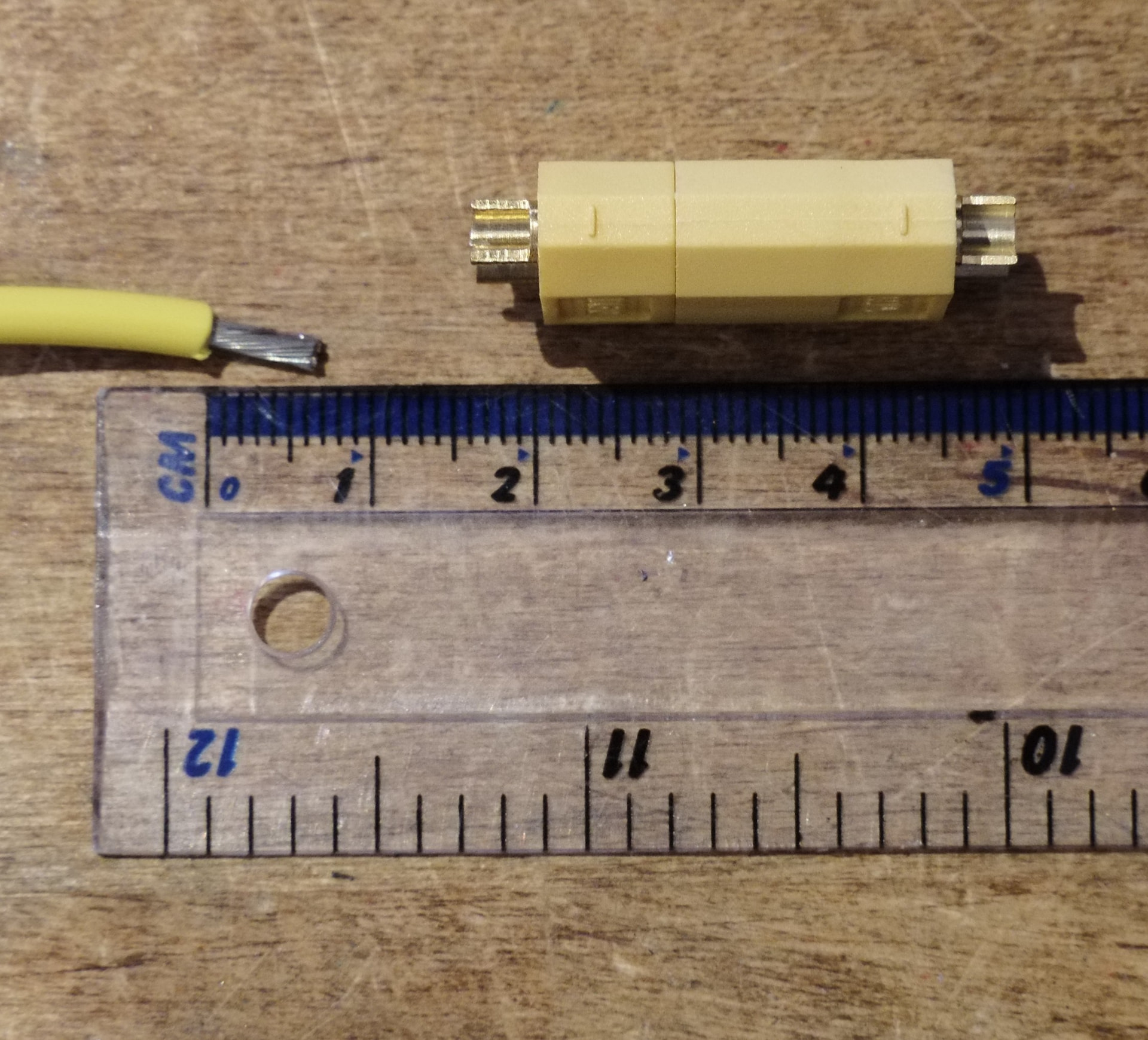
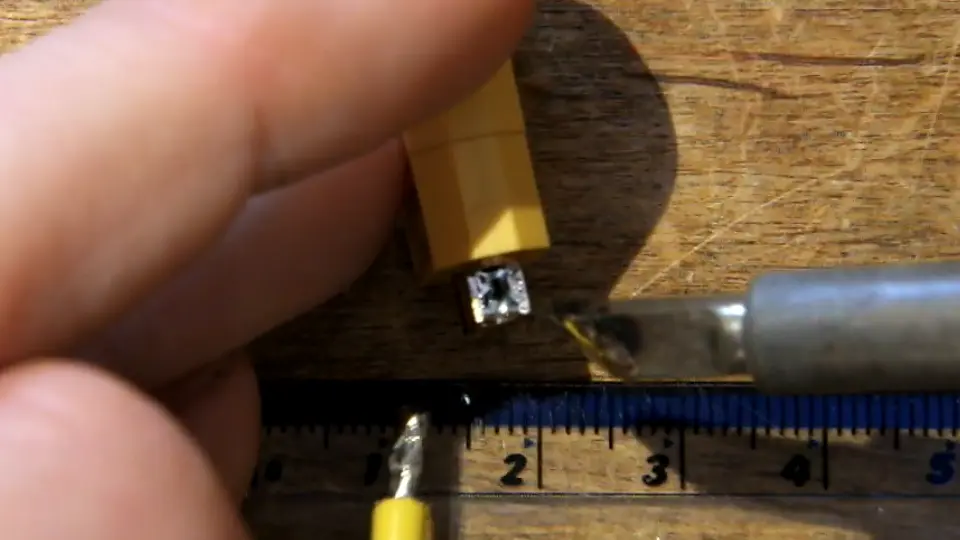
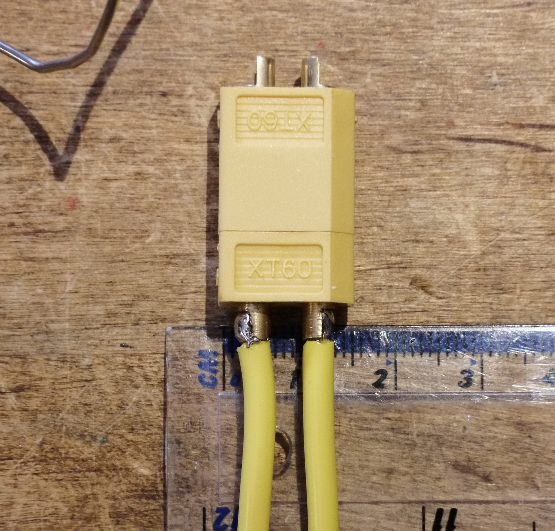
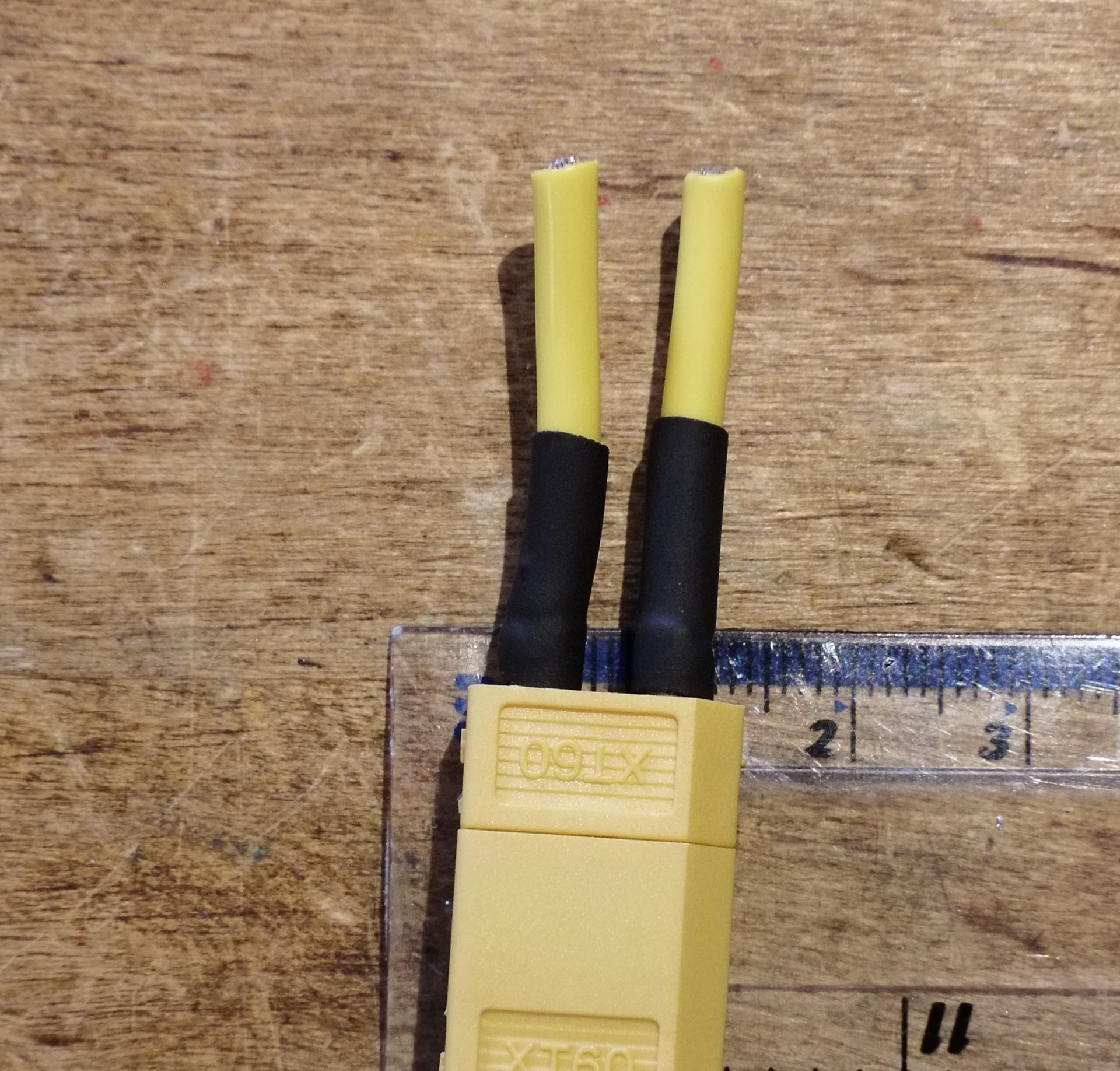
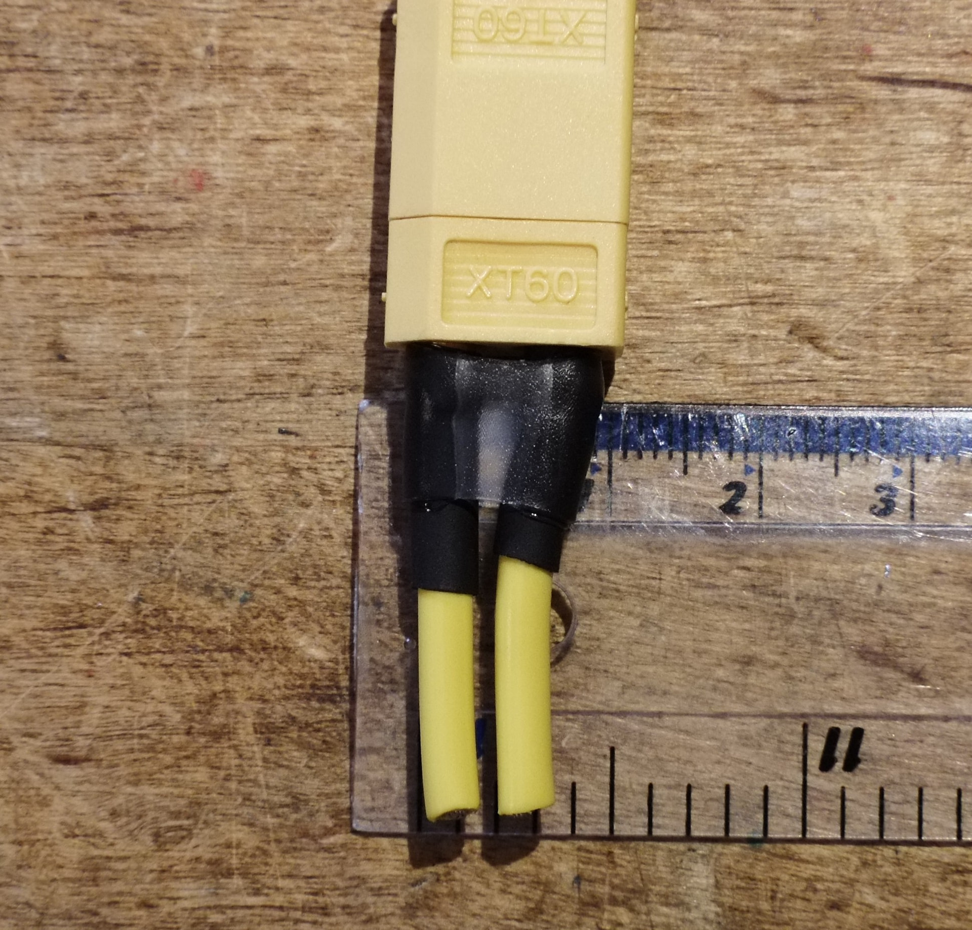
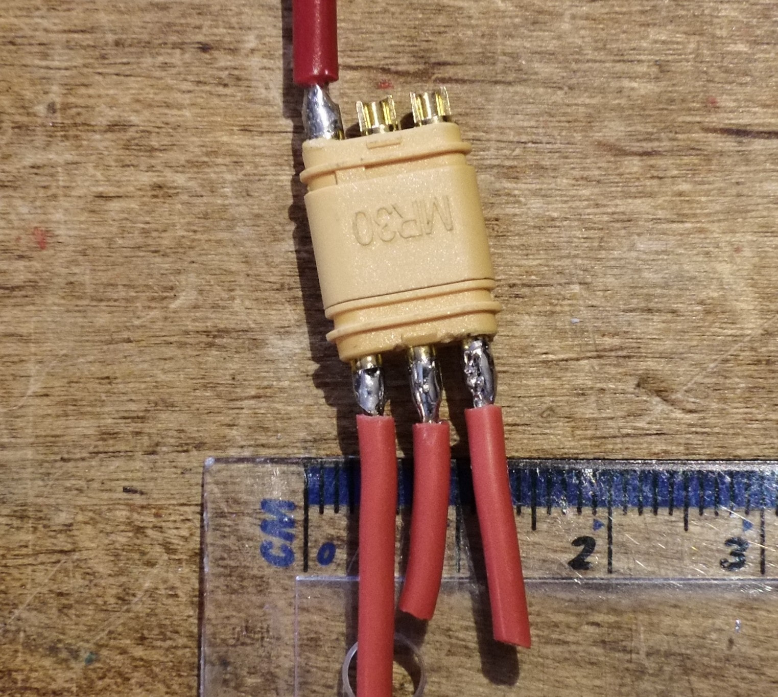
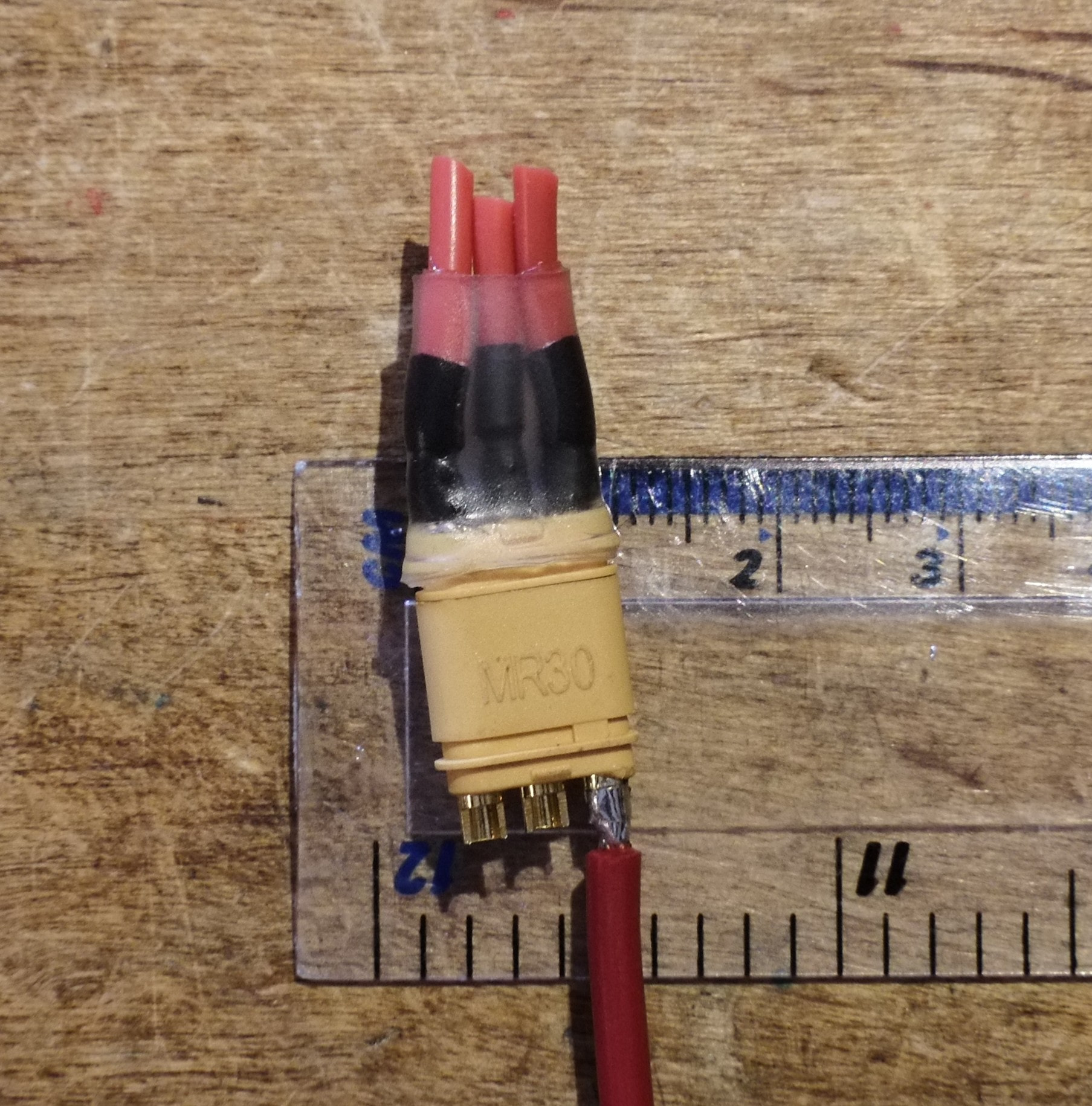
- XT60/XT30/MR30 connectors
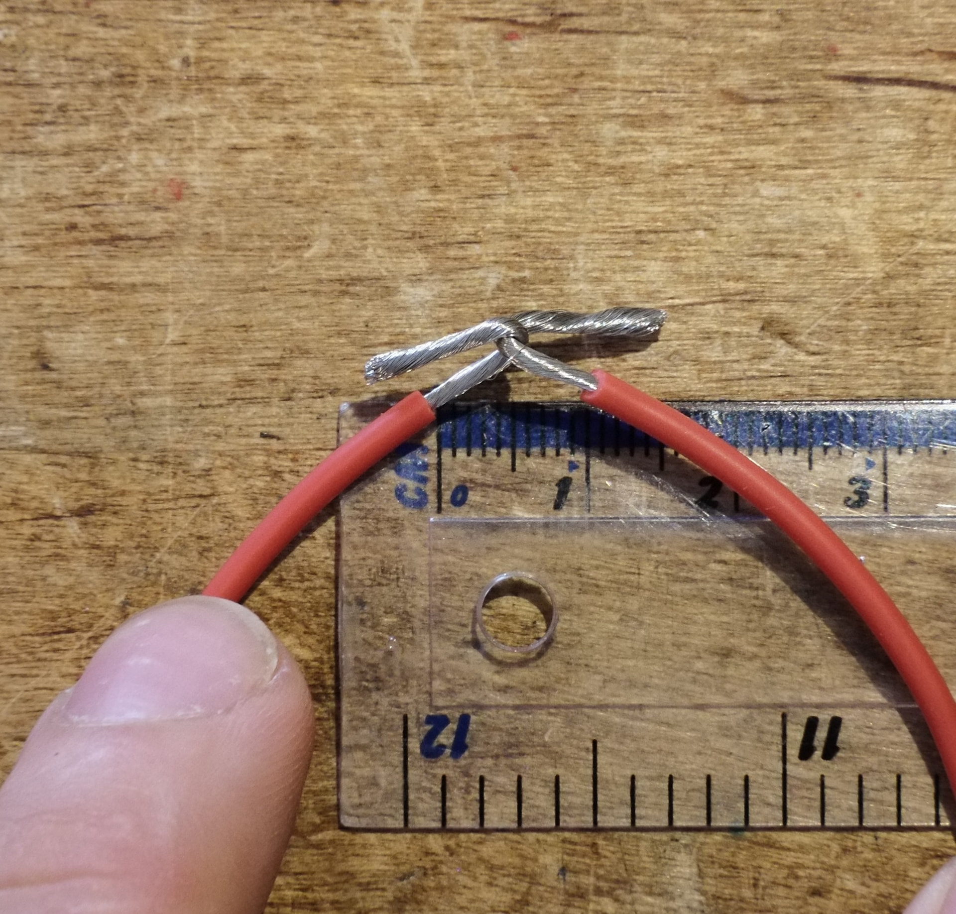
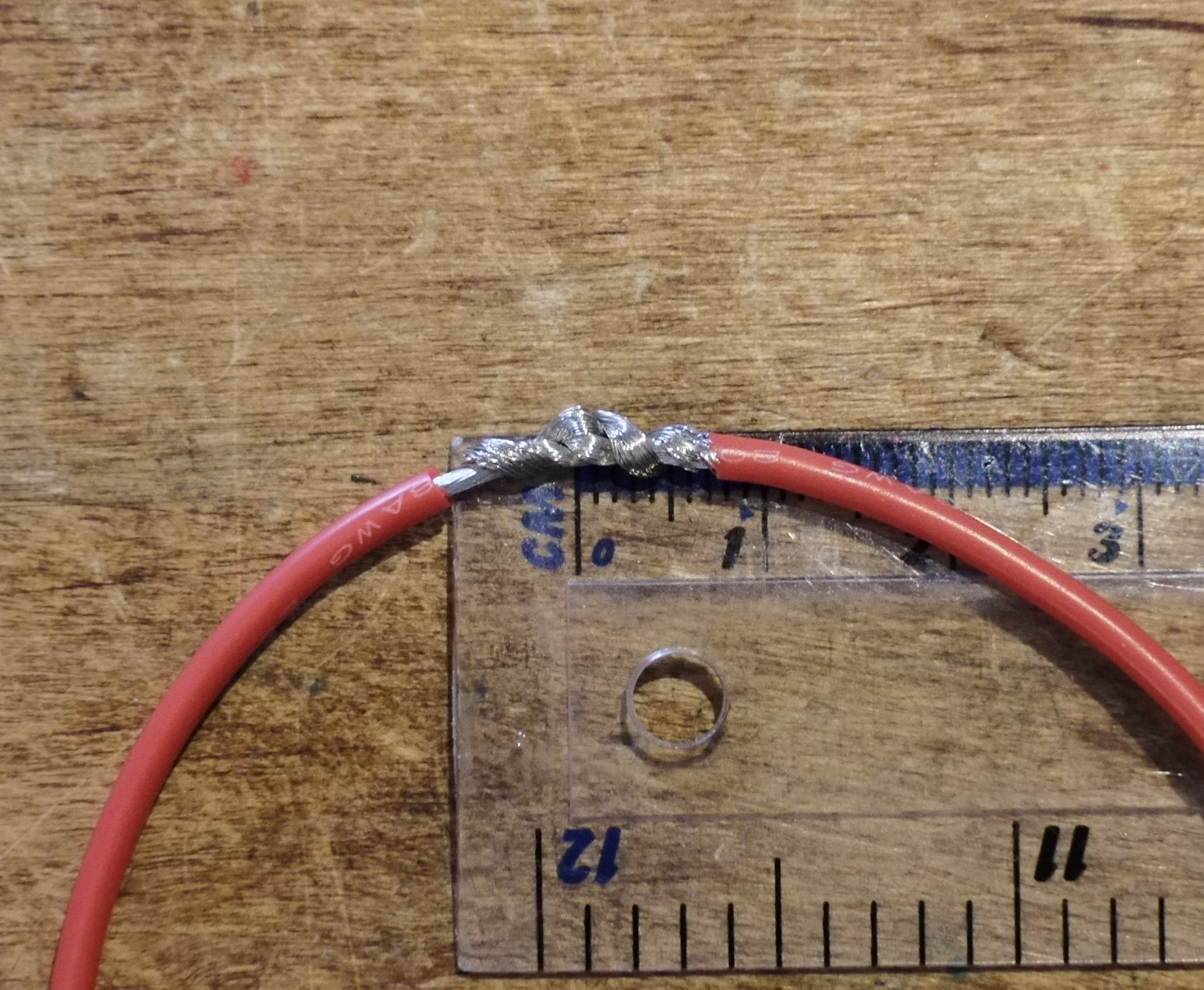
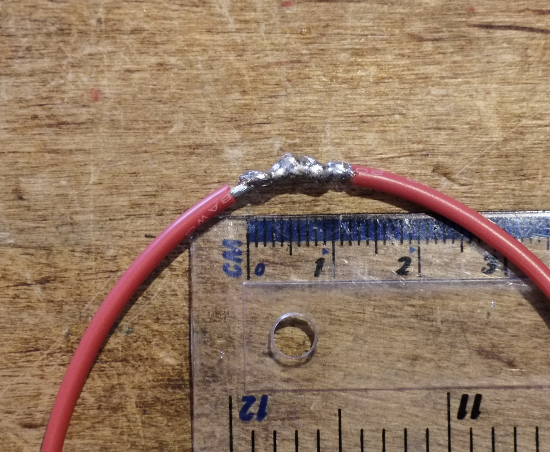
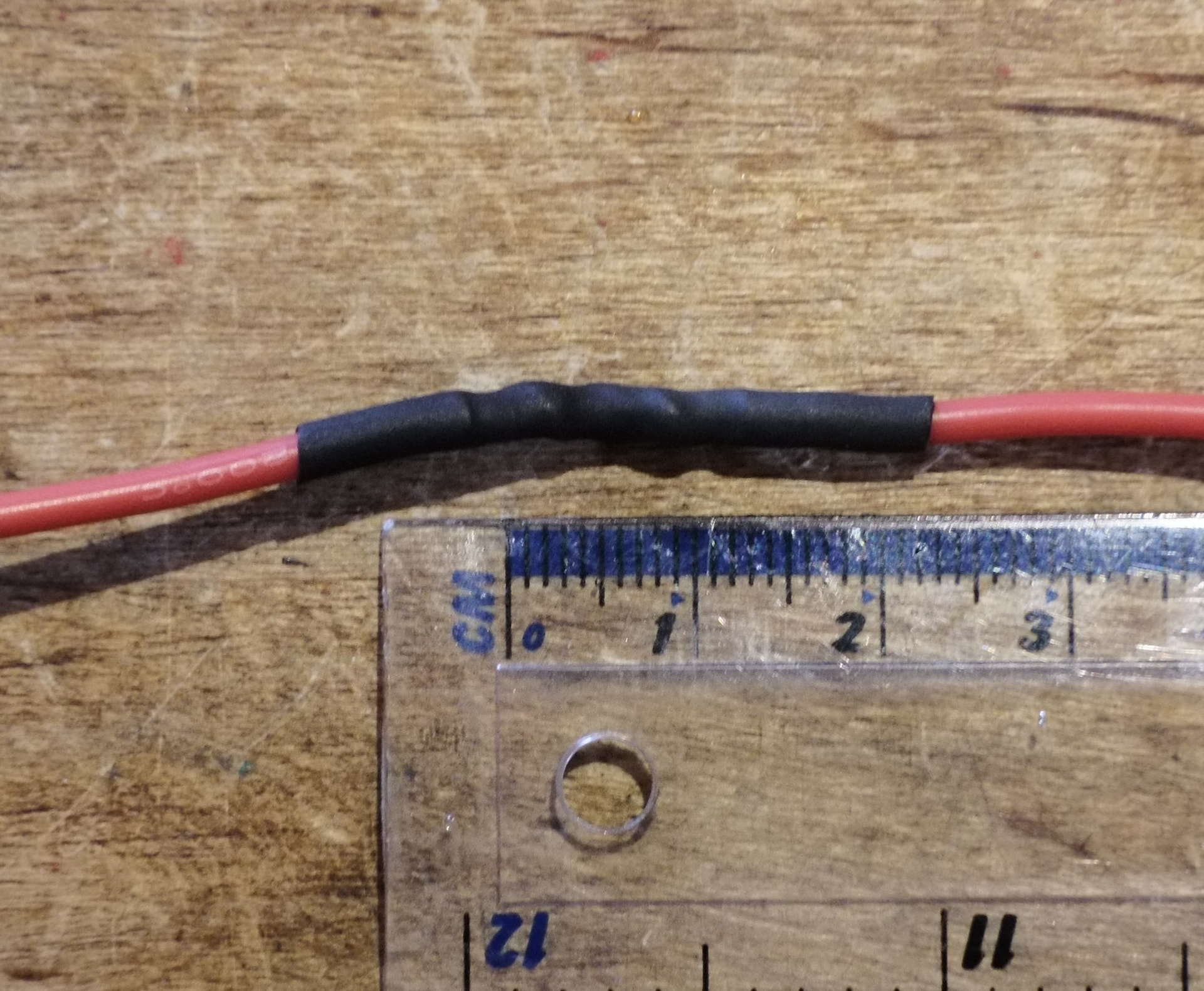
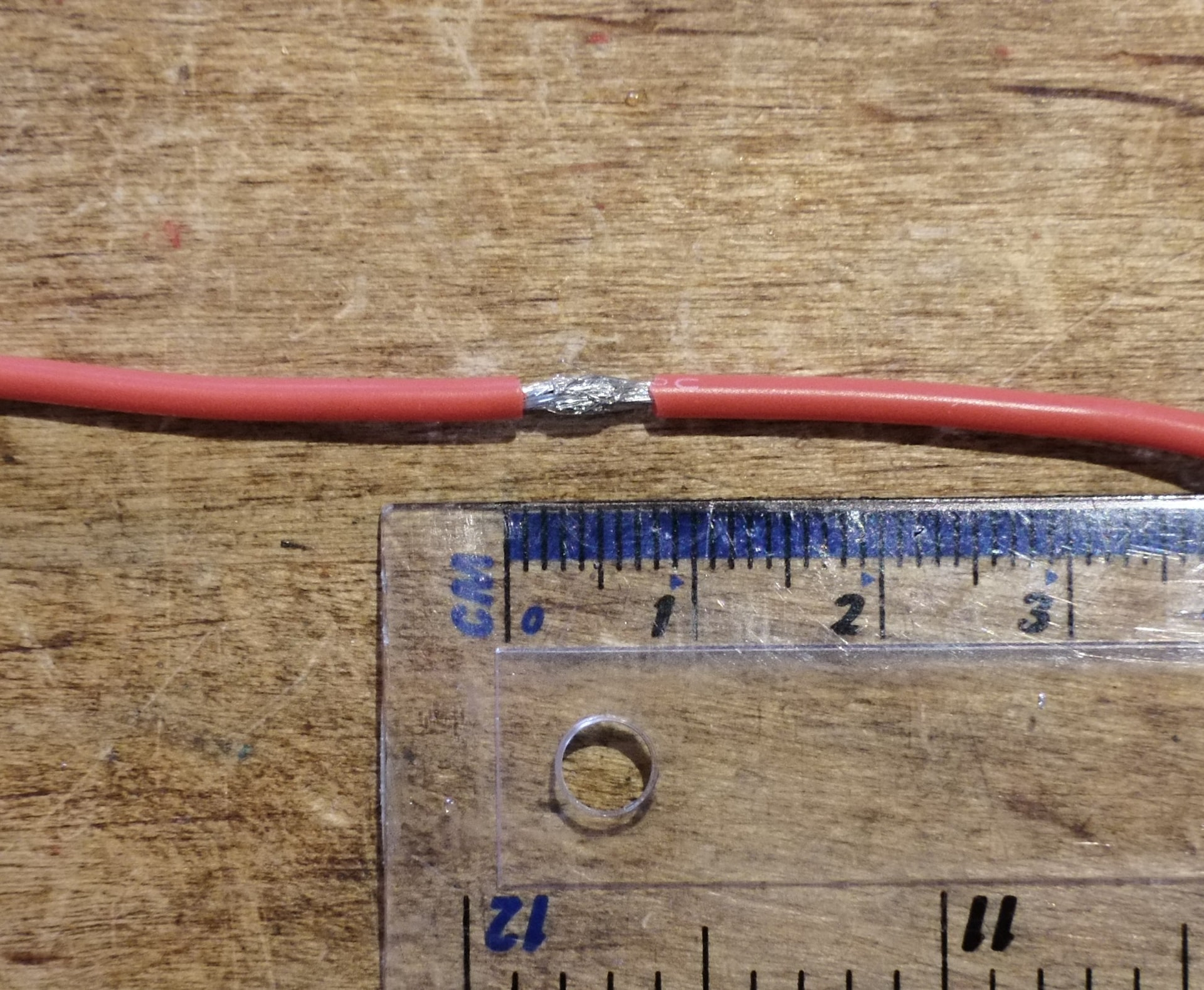
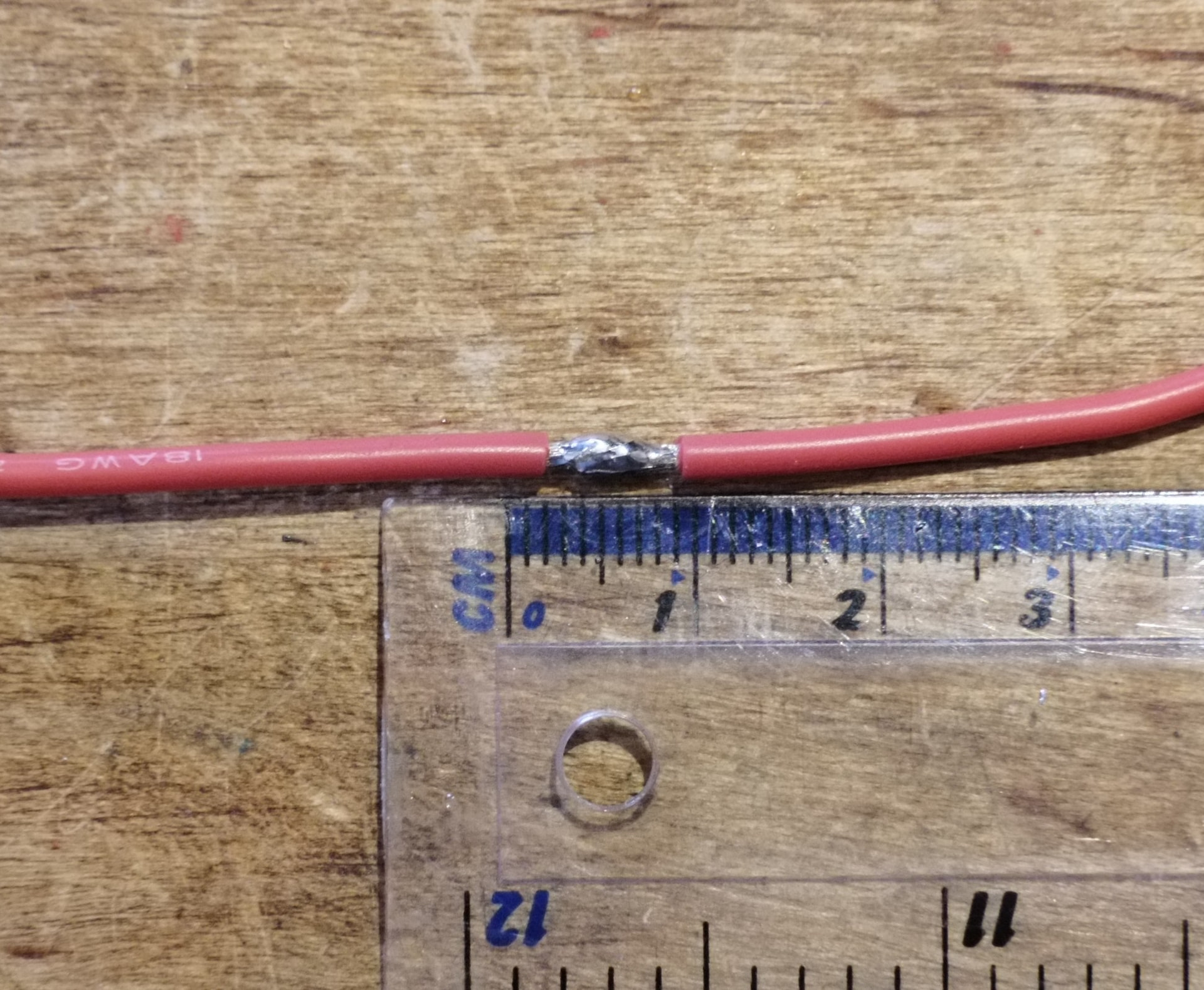
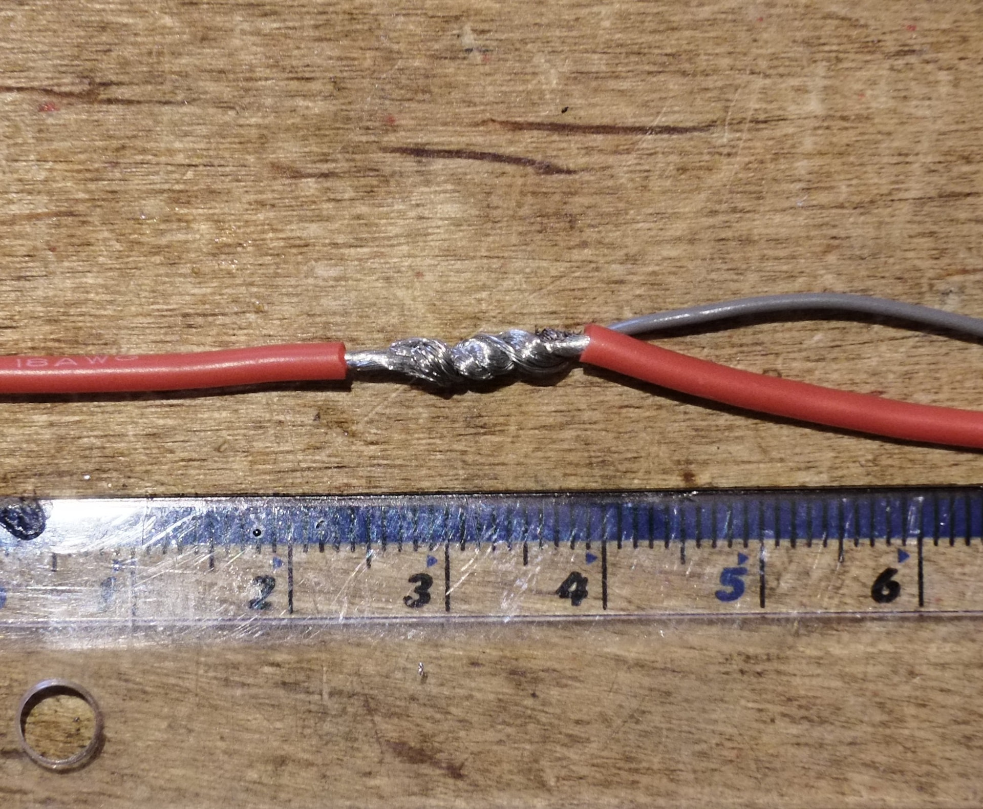
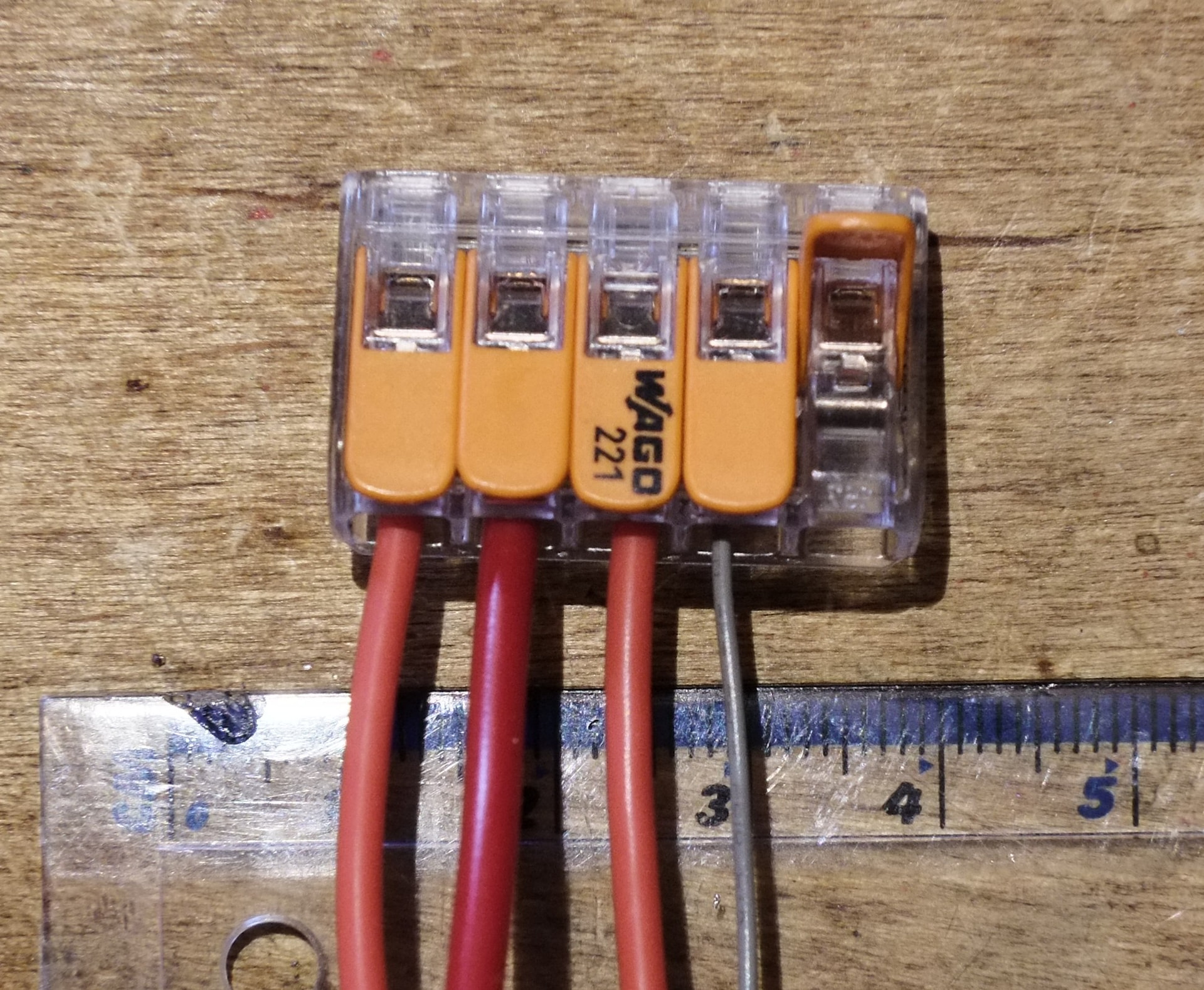
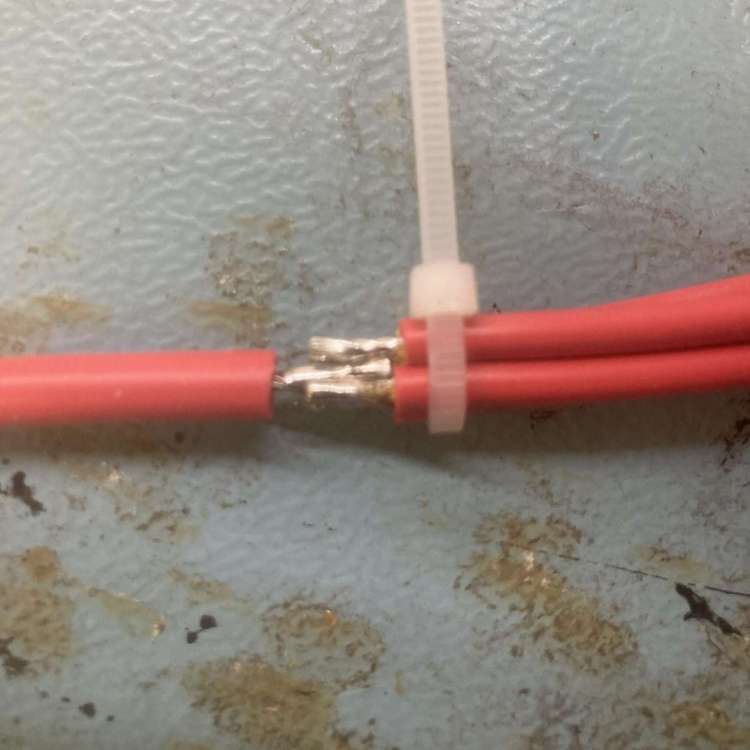
- Wire splicing
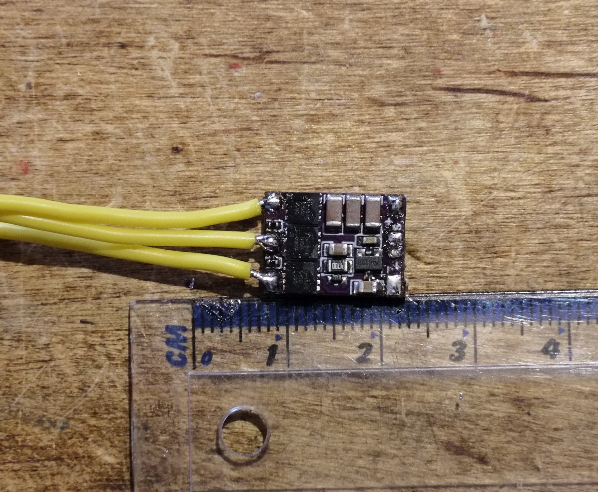
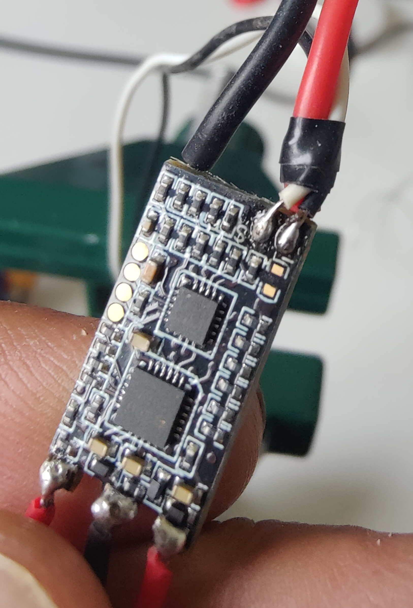
- Surface mount wire pads (ESCs etc)
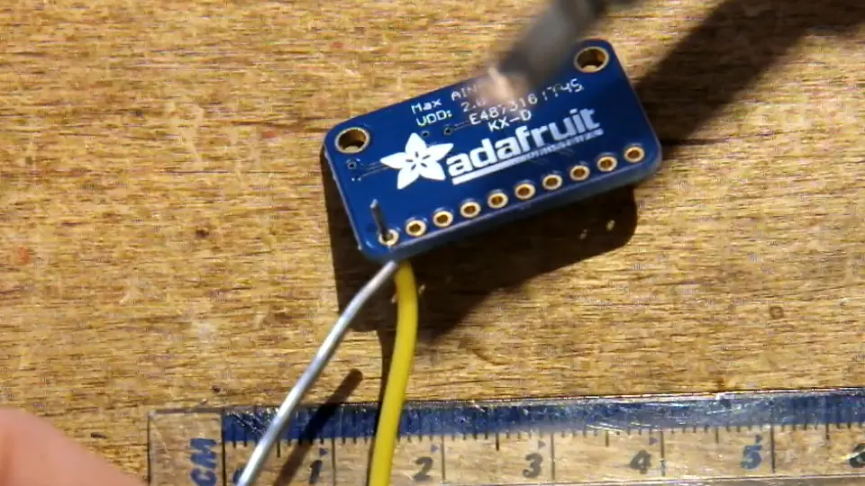
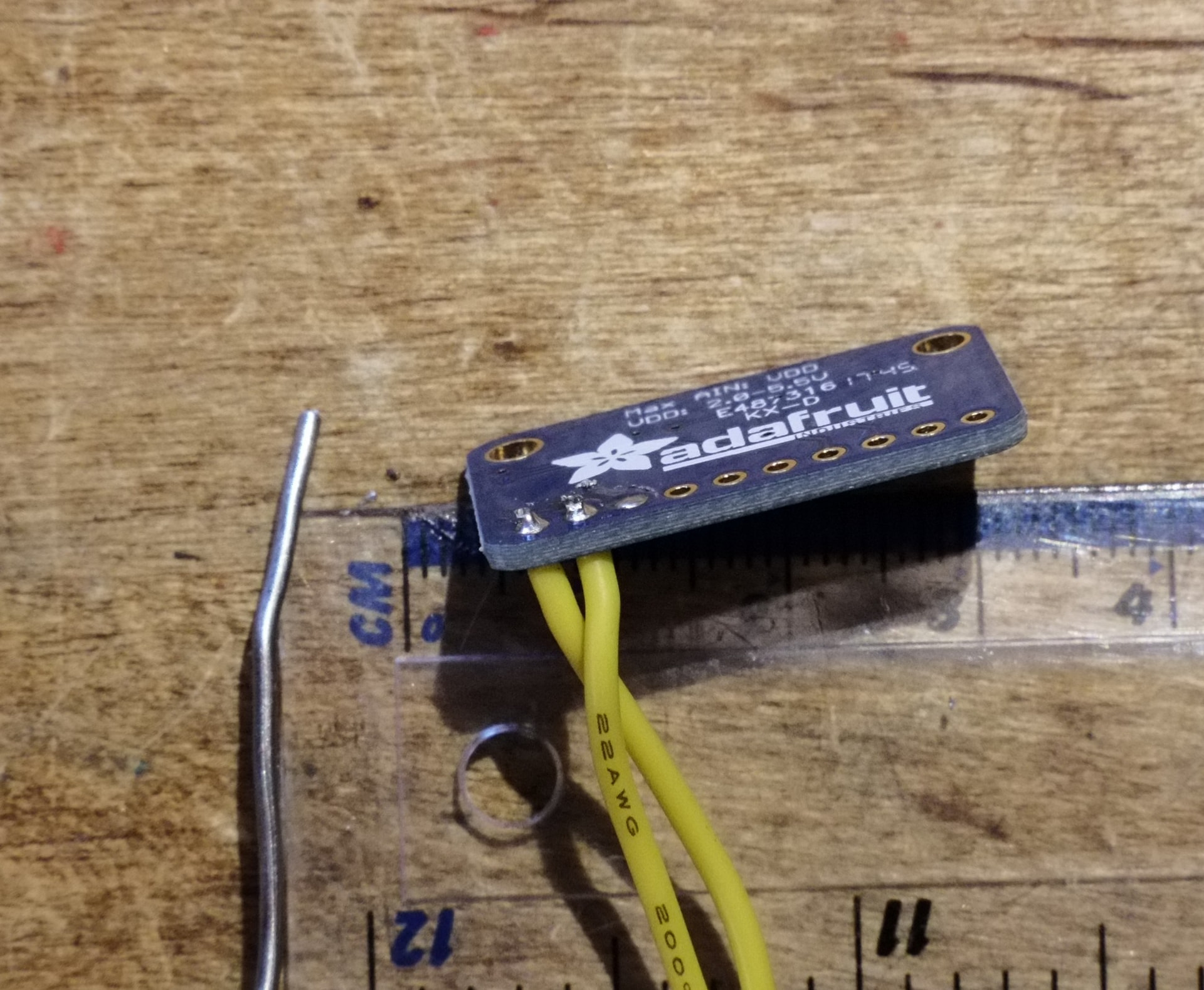
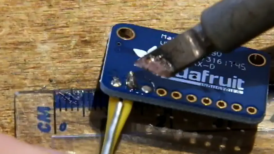
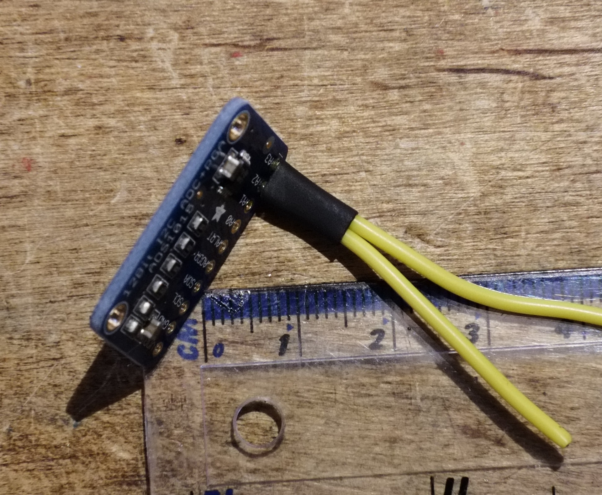
- Through hole wire pads (Receivers, Malenkis etc)
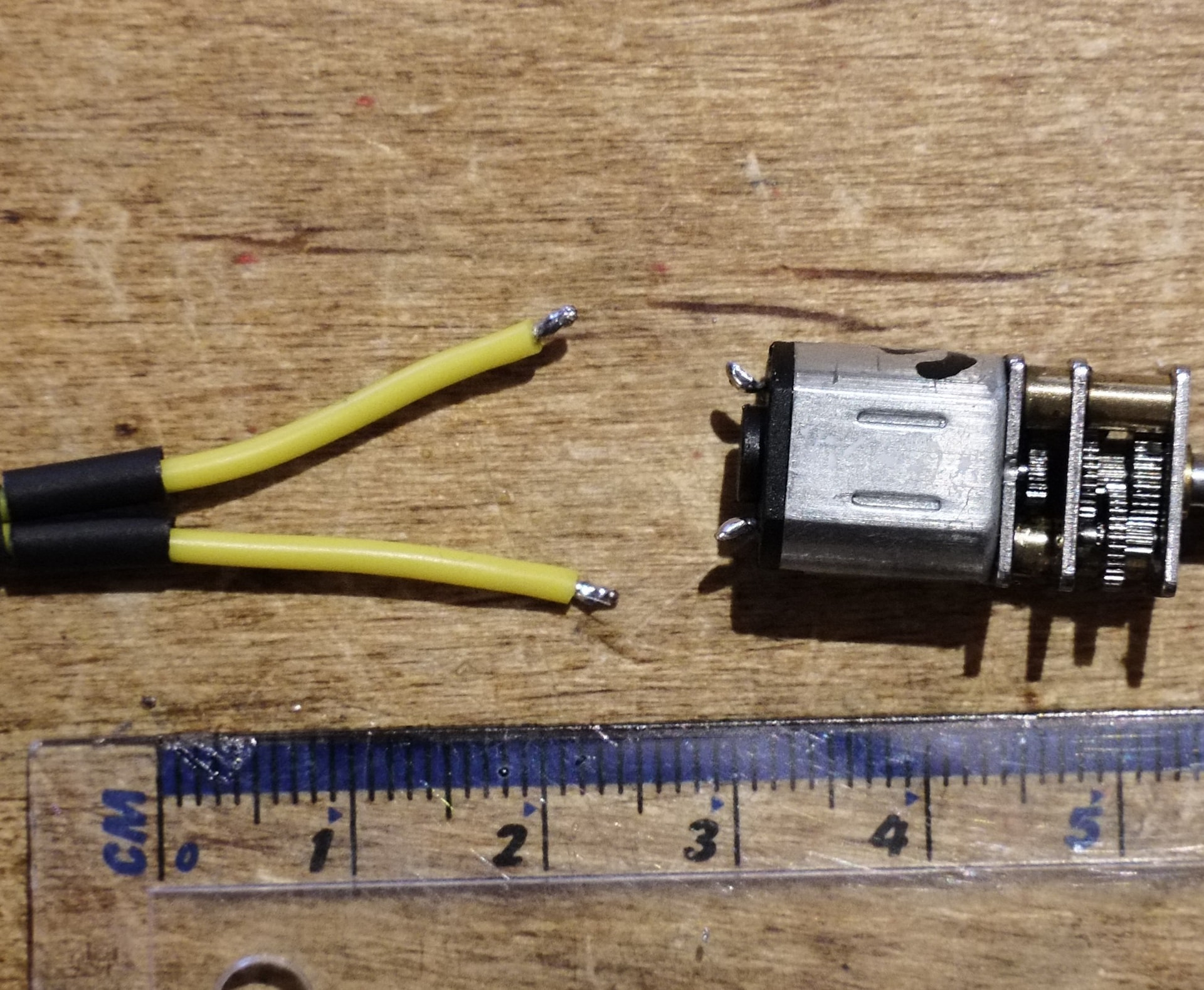
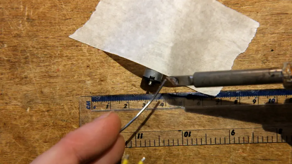
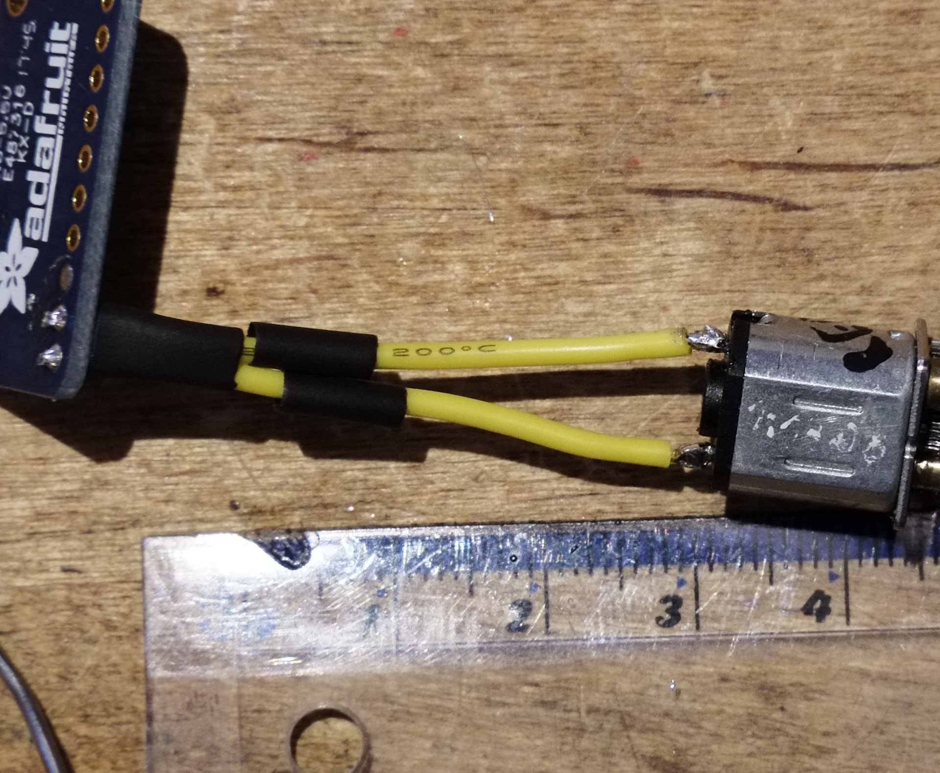
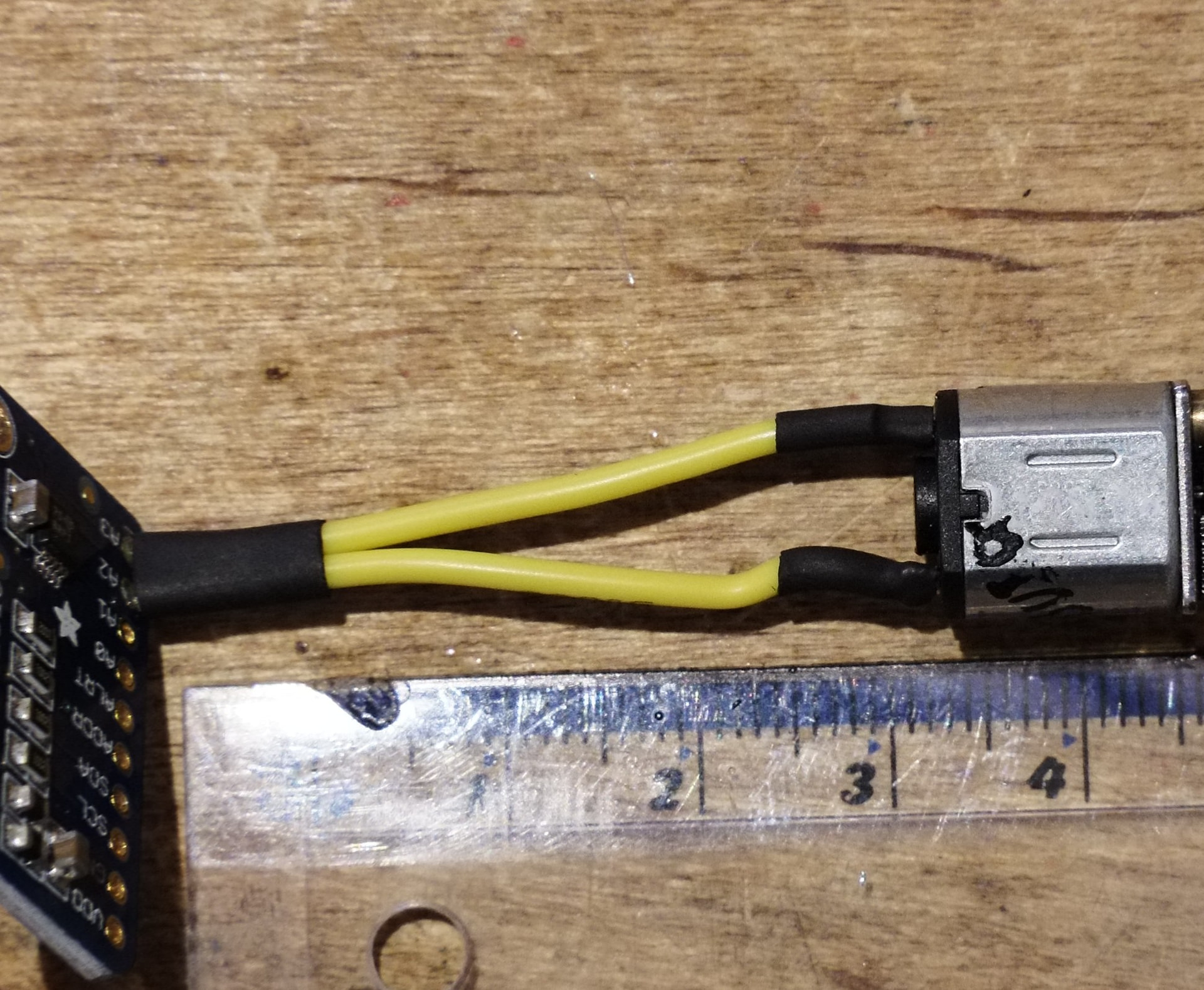
- Solder tags (Brushed motors, switches etc)
I believe that covers the majority of your everyday robot soldering, but if I have missed anything please let me know - I will be taking requests!
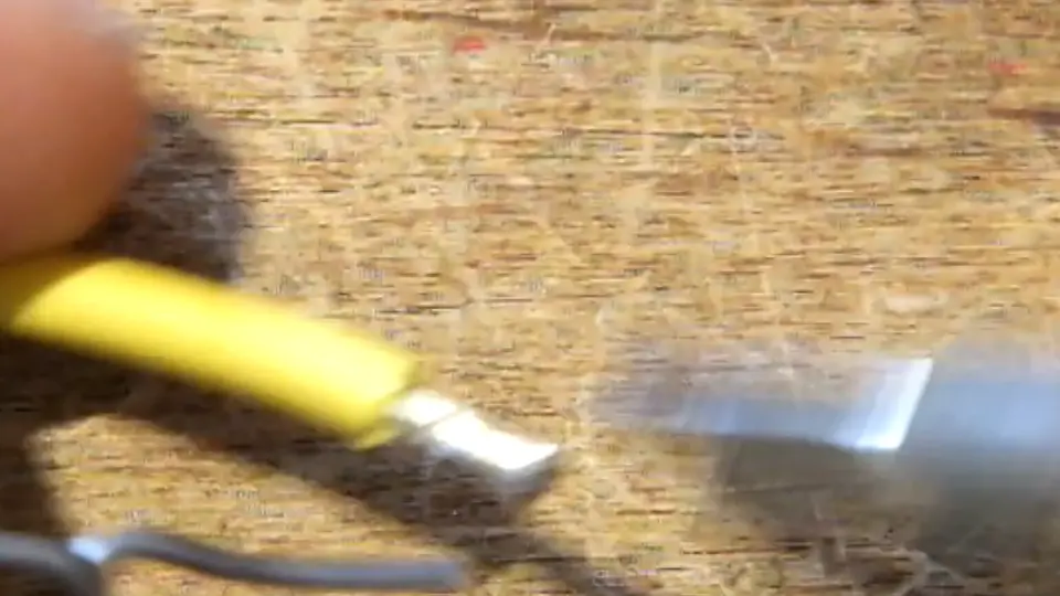
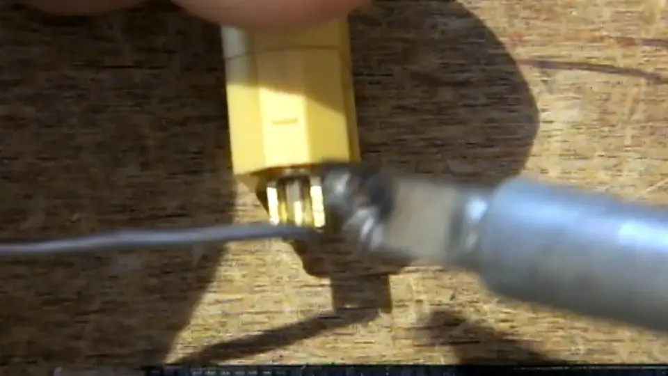
I will also apologise in advance if any of the photos or video clips are out of focus, badly lit, or obscured slightly by my hands. I had to do all of this with a camera on a tripod between me and the work, and at times it was more than a little awkward!
Equipment and Consumables
Soldering Irons
IMO one of the most pervasive and detrimental myths in soldering is that for vaguely small stuff you need a really tiny iron. Unless you are doing really, really tiny surface mount stuff under a microscope, this is simply not true. Below is a photo of the two iron tips I use most, for everything from surface mount (down to 0603 passives and 0.5mm pin pitch ICs) and tiny 26AWG antweight wires all the way up to 14AWG featherweight wires.
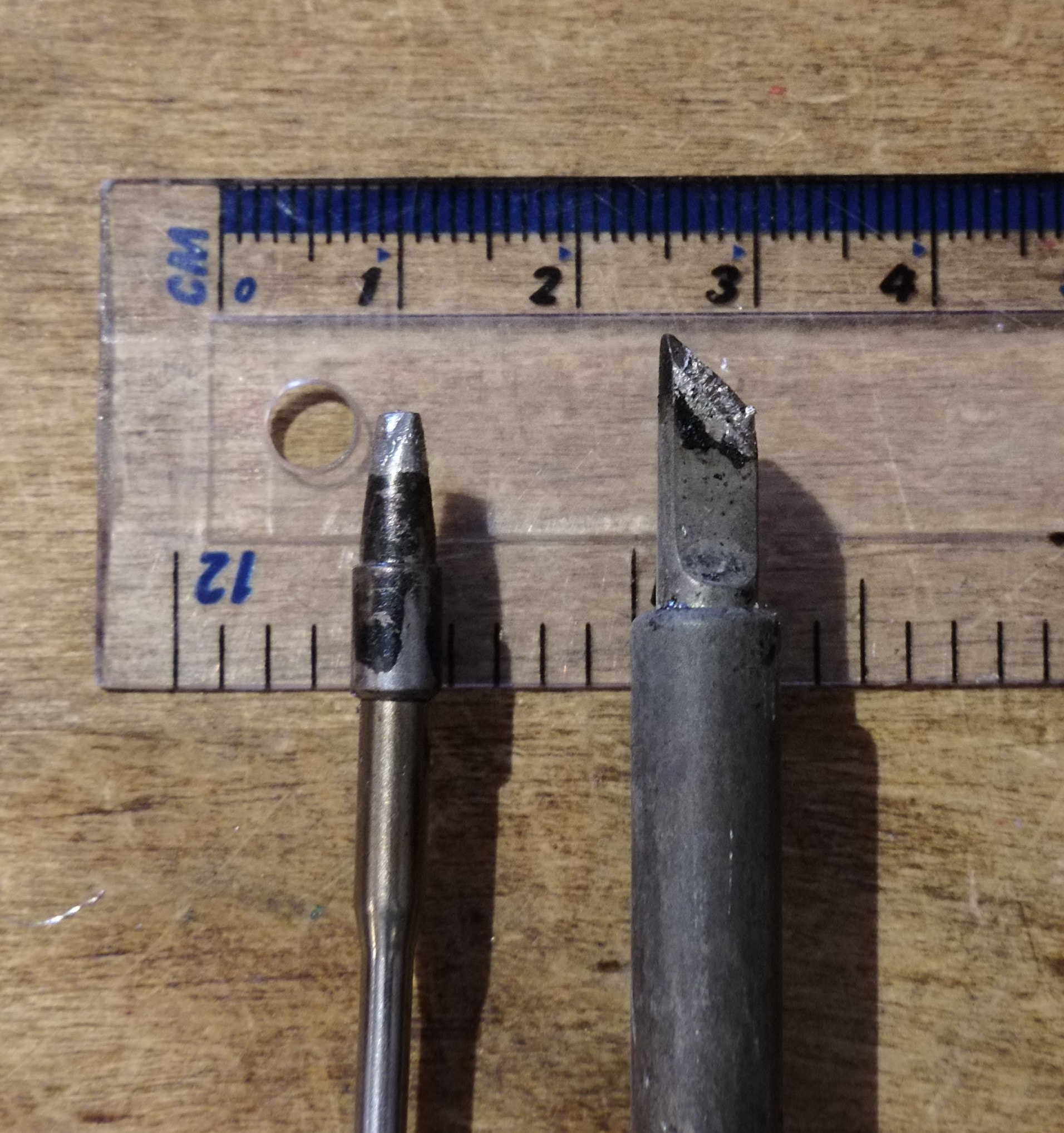
Left is a USB-C powered TS80 I use at events, right is a benchtop generic ebay jobber I use at home. The large tip size provides a bunch of thermal mass, so even the tiny 18W USB-C iron can punch far above its weight, as when you dump a bunch of solder into a joint, the iron stays hot. If you use a tiny tip, just touching it to the joint is sometimes enough to bring the temperature down below the melting temperature of the solder. This means you have to keep the iron on the joint for far longer than a big tip, which increases how much heat is pumped into the board, and can cause blobby ugly joints, melted insulation, and lifted pads - remember PCB pads are only held to the fibreglass substrate with glue!. The important thing here is that both tips have sharp edges, so you can still get a corner of the iron into a small joint while preserving thermal mass.
When it comes to choosing a soldering iron, something with real temperature control is a huge benefit. An iron with a screen and buttons, or numbered temperature dial, usually means it has a feedback loop inside, which means that it’ll sit at a constant temperature when in the stand, but when you start soldering the feedback loop will crank up the output power as much as it can to preserve the temperature at the tip of the iron. This is much easier to deal with than an unregulated iron, which will fluctuate wildly and can leave you with cold joints and a cooked tip at the same time. You should avoid this style unless it’s literally all you can afford and someone gave it to you for free:
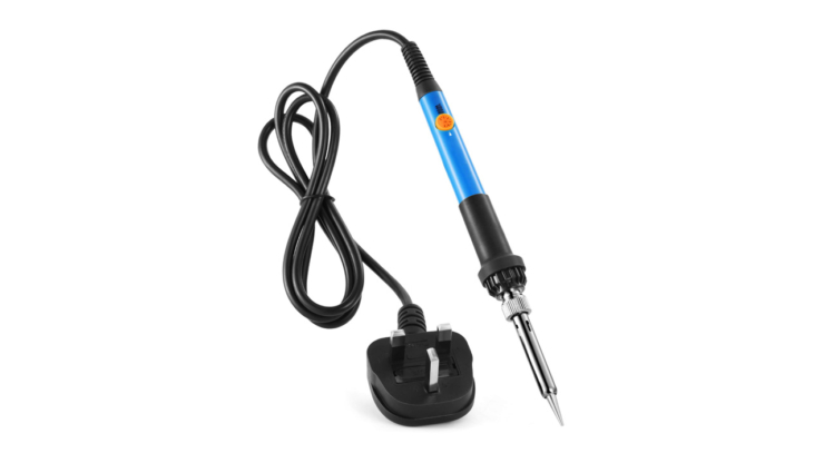
Slightly more usable but still not ideal are power-adjustable irons. While they do have a dial, it’s just a volume knob - the iron might change temperature in the stand, but it does it by lowering the total power, so there’s no way to have a cool iron that can still solder big connectors without it slowly cooking itself in the stand. They can be identified by their vague, un-numbered dials:
Thankfully you no longer have to spend £300 on a lab-spec Weller to get good temperature control, as China makes a whole range of pretty decent adjustable irons for cheap. Ideally you want to pick something of at least 60W, assuming it’s a standard interchangeable sleeve tip and not something more fancy. My TS80 has the heating element baked right into the tip, which is how it gets away with only being 18W, but the downside is that new tips are expensive and have to be treated with some care. The OG TS80 is discontinued now, but the manufacturer Miniware has a range of similar irons (USB and barrel jack powered) for not crazy money. There’s also the Pinecil and a few other options of its ilk, but I’m not massively familiar with those as I’m still happy with my TS-80. TL;DR if you can change the temperature and it wasn’t £12 on Temu it’s probably fine.
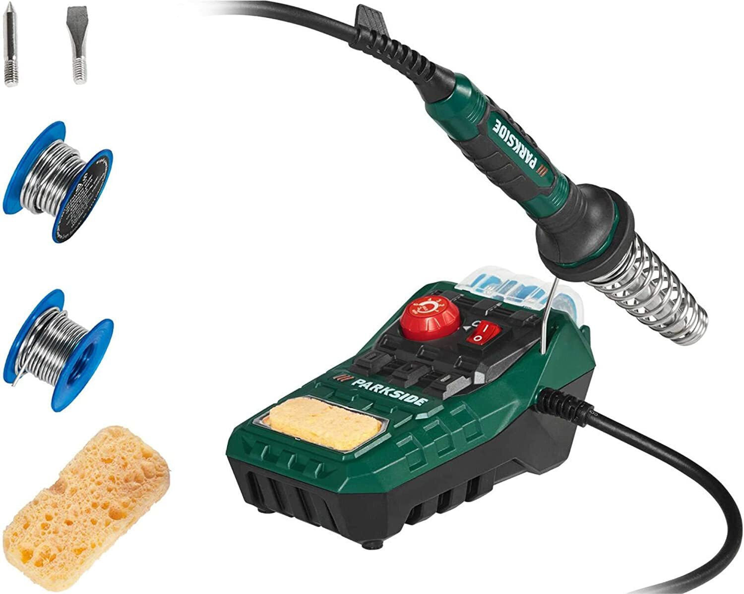
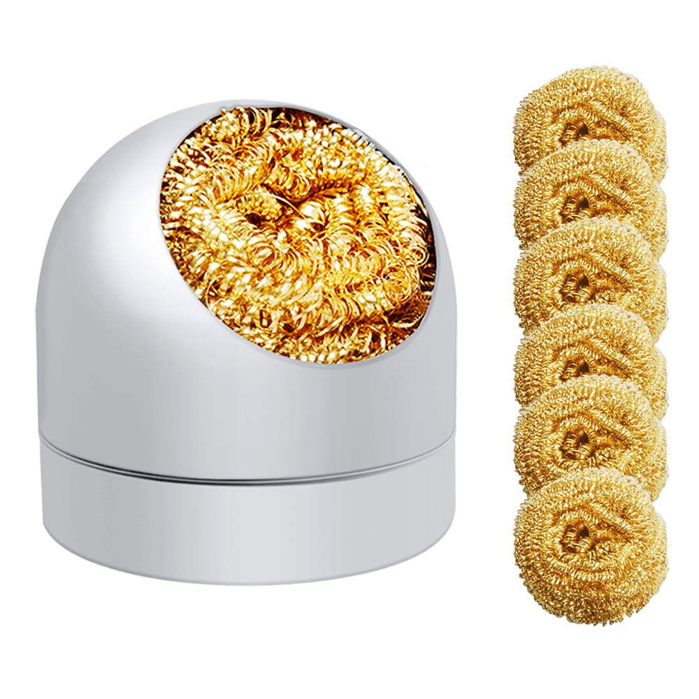
You will notice the Parkside iron photo contains a sponge. This is for keeping the tip clean, which is vital to good joints. Sponges aren’t great, because putting a hot iron into a wet sponge will cause some amount of thermal shock and eventually damage the plating. I prefer these brass pube-style tip cleaners:
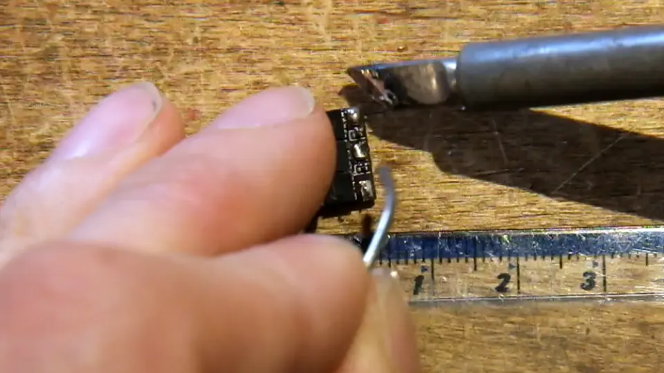
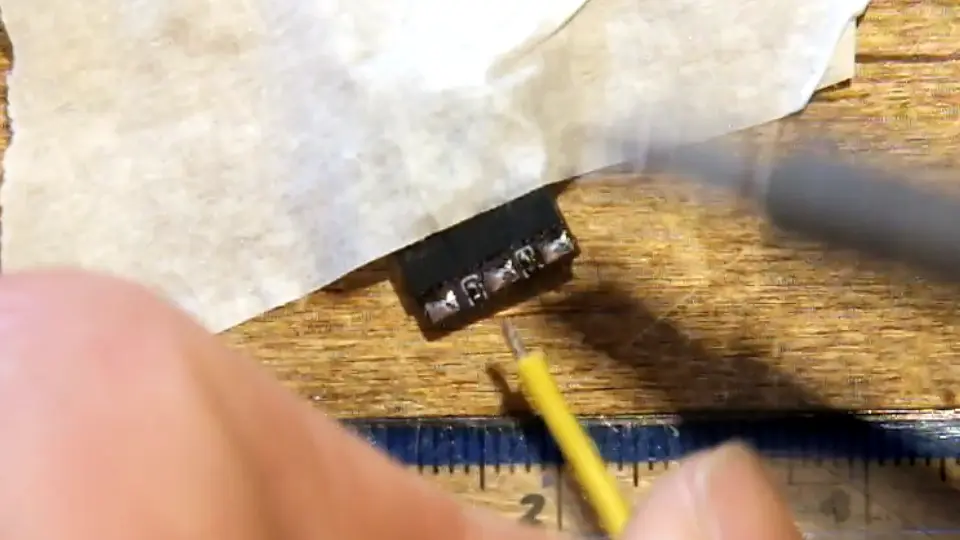
Finally, after getting tired of people’s “my iron is too big for X or Y” excuses on the internet, I decided I needed to make a point that it’s more about heat management and tip geometry than overall tip size, so here’s a video of me soldering an 0805 (2x1.25mm) surface mount resistor with a ~20x30x50mm roofer’s soldering iron that I heated up on a gas stove:

Consumables
There are two main choices for solder composition: 60/40 (or 63/37) tin/lead, and lead-free. RoHS (regulation of hazardous substances) rules mean that manufacturers are no longer allowed to use lead for production stuff, which has made it harder and harder to buy in recent years, but IMHO it’s still the optimal choice for home gamers. While lead free solder is finally good, the real good name brand stuff can be expensive, and the cheap stuff (think the little coil in a tube that might have come free with your iron, or you bought at the high street hardware shop for a fiver) is pretty nasty and makes everything that much more difficult. Yes, the lead stuff contains lead, but it’s not as bad as it sounds - I’ll cover that in the safety bit.
It’s really best to pick a flavour of solder and stick to it. Switching between solder types regularly isn’t really advisable, as the solder bonds with the tip plating and you’ll never really get rid of all the old solder - this can cause bad joints, or damage the plating. If you spend a lot of time working with things that have previously been soldered with lead-free, it’s best to stick with lead-free solder for everything, or at least keep separate irons/tips. Most generic Chinese-manufactured use the same four-pin GX16 “aviation” connector, and new irons aren’t too expensive, so keeping a couple on the rack with tips dedicated to different jobs isn’t the worst thing.
Flux is really, really useful. If you’ve ever watched Louis Rossman repair Macbooks on youtube you’ll know that there’s no such thing as too much flux (until it comes to cleaning time). While solder does (or should, unless you accidentally bought plumbing solder) have a flux core, supplemental flux is a good idea. It’s a high temperature fluid or gel that coats the surface of the joint and prevents air getting to the molten metal and oxidising it. An oxidised solder joint won’t flow right, and will cool in a weird crystalline lumpy mass, but the good news is that if this happens you can just blob some flux on top and re-flow it with your iron and it will reform nicely. Any oxide will be pushed to the surface and stick to the flux residue, ready to be cleaned off later.
I like flux pens, as you can just scribble and squish some out into the board without having to scoop it out of a tub. I like Chemtronics or RS Pro, and would recommend avoiding generic cheap options as it’s a bit of a gamble whether it’s any good or not. Look for no-clean flux rather than anything else, I once bought “water soluble” flux by accident and even when I thought I had washed it off, after a couple of weeks all the numbers coming out of my prototype looked funky. When I opened the lid of the box the flux residue was turning all the copper on the board into green fur.
If you find yourself cleaning up after yourself a lot, solder wick is really useful. It’s a woven copper strip coated in flux, and if you bring a cleanly cut end (with a bit of extra flux soaked into it) into a molten pool of solder it’ll suck it up into the wick and save you a bunch of time.
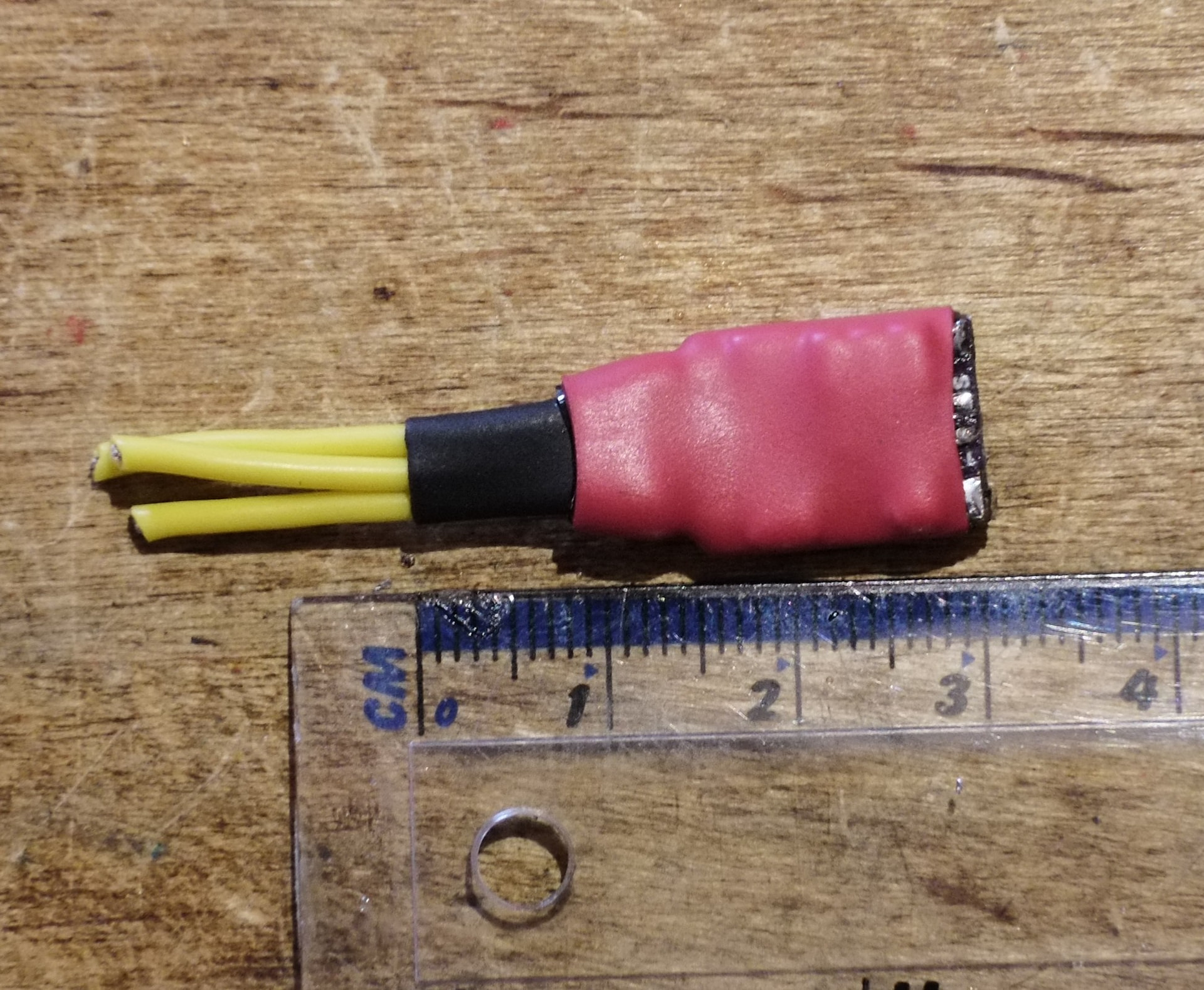
A selection of heatshrink in different sizes is crucial. I like to have some glue-lined stuff in larger sizes for strain relief. Do not use electrical tape - it’s not heat-resistant, so if your bot gets hot it will melt and expose solder joints. It will turn to goop if you leave the robot on a shelf for a couple of months between events. Everything will be sticky. Don’t do it. If you really must use tape, use kapton tape. It’s a little pricey for a roll, but it’s extremely thin so a small reel is miles of tape. It’s heat resistant up to about 350-400c. It’s used on spaceships and is a cool gold colour. Do not use electrical tape.
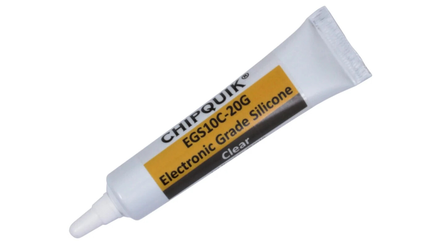
Strain relieving goop is also really useful. Some folks use hot glue, but I don’t like it for a couple of reasons. The first is that it’s actually pretty hard once set (especially if you’re somewhere cold, like Robodojo in December), so it just shifts the strain to a different part of the wire. The second is that it doesn’t stick very well, and it’ll often peel off PCBs and cease to relieve any strain at all, sometimes even making the problem worse as it pulls the insulation back up the wire. Instead I prefer to use neutral cure/electronics grade silicone. This is basically the same consistency as clear bathroom silicone sealant, except it doesn’t release acetic acid when it cures, so it’s safe to use on electronics. My go-to brand is Chipquik, although it’s only worth buying as an add-on to an existing order from Rapid/Farnell etc, as it’s about £4 a tube there (where the free postage threshold is about £30) and about £12 a tube anywhere with free postage.
While I haven’t demonstrated it at all in this thread (due to my tendency to get any goopy chemical absolutely everywhere and also me leaving the lid off the tube and it turning into a solid lump of rubber), do keep it in mind, as for any of the joints in this post there’s probably a way you can goop it up with silicone and add some extra strain relief.
Other Tools
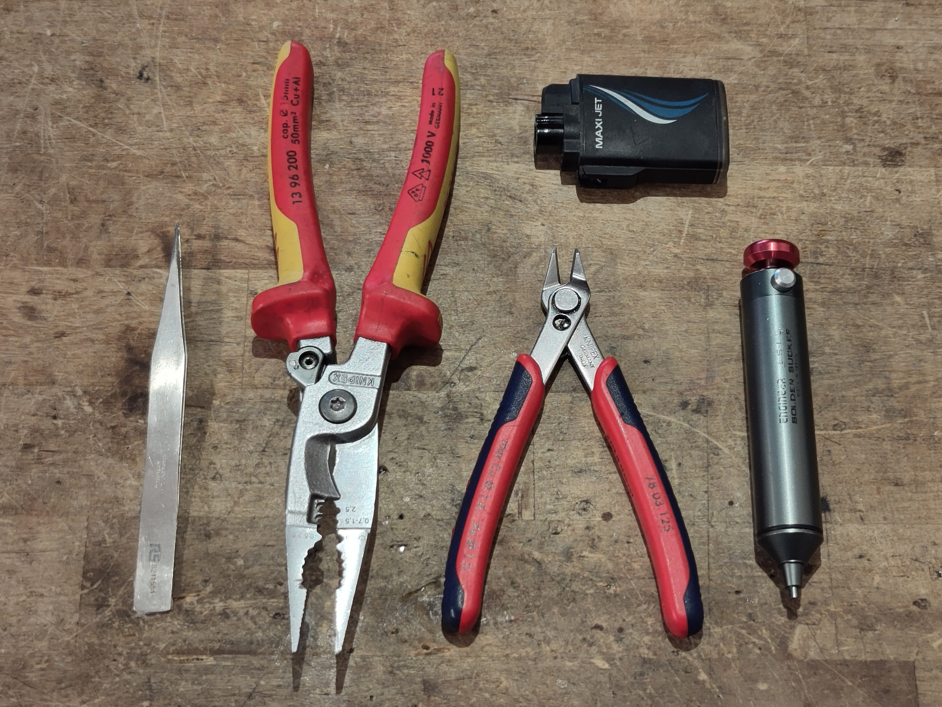
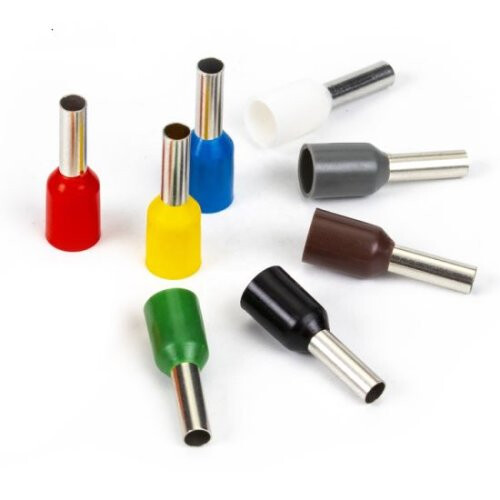
You will need some other tools. Side cutters for cutting and stripping, and something for heatshrink at a minimum. Above is what I keep in my tool kit - the Knipex stuff is a little bougie for hobby stuff (but top notch when you’re upside down under a test rig, yelling expletives at whoever worked on it last), but since I now work freelance I have to provide my own tools that I know I can depend on, and I really like the Knipex stuff. The big cutters/strippers/pliers/ferrule crimpers are probably a hard sell for home gamers, but I do really recommend the side cutters, and they’re not too expensive compared to a generic set. I have always found that the generic cutters you find in in the workbench doom pile at hackspaces to be uncomfortable and fragile, and more than once I’ve tried cutting a wire and had a tip fly off in the opposite direction.
While I use a battery powered hot air gun for heatshrink at home, I keep the jet lighter in my toolkit to use at events and when working in the field. It’s better than a regular lighter as it works in any orientation without burning your fingers, and you can keep the heatshrink well away from the flame and shrink it without charring it.
The grey jobber on the right is a solder sucker. These are amazing for quickly removing large amounts of solder from pads, and from clearing through-holes of solder. I really recommend a genuine Engineer brand sucker like mine - they’re reasonably priced, compact, and have more suck than any other sucker I’ve ever used. There is a knack to using these - some fresh solder on the joint helps a lot, and so does waiting a couple of seconds longer than you think you need to.
Finally, YMMV but I really appreciate tweezers for working on my obnoxiously compact robots without burning my fingers, even if they make me feel like a pretentious chef plating micro-greens while I use them.
Safety
Lead solder sounds scary, but metallic lead on its own is actually not particularly dangerous. It’s so unreactive that your body doesn’t really absorb it very well, so any damage is usually done through A. cumulative exposure to high levels, or B. more bioavailable lead-containing compounds. The Romans all had lead poisoning from lead acetate, caused by heating vinegar and acidic wine in lead pots. Lead in general is pretty low on my list of “ways you can die doing robots”, far below “testing a spinner outside of a safety box while standing next to it” and “breathing lipo smoke”.
As I mentioned above, I’ve been soldering for over 20 years, mainly with lead-based solder as I’ve mostly been soldering at home for hobby purposes or at work with lead for non-production R&D purposes. A couple of years back I volunteered for a blood test for lead at work, as we had a colleague in another team who was worried about sharing a lab with people soldering with lead while trying for a baby, and I wanted to reassure them that they didn’t need to take any special precautions aside from not doing the soldering themselves if they felt uncomfortable with the idea. The results came back as below the detection threshold for the test, meaning that to the surprise of people who know me I do not in fact have lead poisoning. The lady on the phone who gave me the results was actually surprised that we’d bothered with the test, as the company “usually only works with people who are moving powdered lead around with shovels”.
This doesn’t mean you shouldn’t take precautions though - don’t chew the solder, don’t lick your solder joints to clean them, and wash your hands before eating or drinking. Don’t put your coffee next to your tip cleaner, as little bits can fly off the tip of the iron and land in your coffee.
A bigger danger than the lead is the flux, as it’s usually some kind of organic compound (often derived from pine rosin) and you’re likely to inhale it. This is actually slightly worse for lead-free solder as it requires slightly nastier, higher temperature flux. Fume extraction is ideal, but it’s not always practical at home, so I will open a window and my office door to get some airflow through the house while soldering, even when it’s cold outside - you don’t want it sitting around in the air while you work. Sometimes you’ll get a face full of flux vapour, don’t huff this. You can blow on it gently instead to get it out of your face.
Also, it shouldn’t need to be said, but I’ll say it anyway. Hot things are hot. Don’t touch the iron. If you drop the iron, don’t try catch it (ask me how I know), just let it fall and pick it up by the cord. If you do accidentally touch the iron (it’s a minor hazard of the process), you’ll probably be fine, as you get a half second or so to escape while it boils all the moisture and oils off your hand. If you do smell bacon and hear sizzling, get it under a cold tap and run cold water over it for a few minutes.
Finally, if there’s any kids or pets around, try keep them away while you’re soldering. They might try eat the solder, or huff the fumes, or yank on the iron cable and have it land on them. I don’t have kids or pets but I did have undergrads and there’s not much difference between a grumpy toddler and a hungover undergrad but YMMV.
General Tips and Tricks
There’s a few things you should always be doing, regardless of the operation you’re performing. The order of operations is as follows:
- If you’ve just switched your iron on, wait for the iron to get to temperature. Some take longer than others, and if you’re impatient the first few joints won’t flow right. Don’t believe the temperature display - often there’s some delay between the sensor and the tip coming up to temperature.
- Clean the iron tip by sticking it in your brass tip cleaner a few times, or wiping it on your sponge. You don’t want claggy old solder making it onto your joints.
- Give it a dab of fresh solder. A little pool of solder on the tip makes all the difference for thermal transfer, as it will flow to provide way more contact with the joint than a clean, bare tip.
- Solder the thing. Solder flows towards heat, so if the solder isn’t flowing the part is either not hot enough, or dirty - sometimes a little sandpaper action helps, especially if a board has been sat out exposed to humid air for a while.
- Don’t push down with the iron! You shouldn’t need any more force than the bare minimum that is required to keep the iron held down to the joint. Sometimes you’ll see people leaning on their iron with all their might - this generally means the tip is too dry and they’re relying on sheer force to get the iron to make contact and transfer heat.
- Let the surface tension of the solder do the work. If you’ve used enough heat and enough flux, and the goldilocks amount of solder, the geometry of the joint alone should provide a nice clean fillet.
- If there’s a little too much solder, a clean iron with a tiny dab of fresh solder usually fixes it.
- Once the joint looks good and you’ve removed the iron, don’t move it! Any movement during cooling will cause the joint to crystallise and weaken. With lead solder this is obvious as it looks milky and lumpy. This is a downside of lead-free solder, as most types always looks a bit lumpy and milky, and you just have to trust that you did it right. If it does crystallise, some flux and a re-flow will fix it.
- Clean the tip again! You don’t have to do it after every single joint, but depending on the size of the joint, sooner or later you will start to get a smooth blob or rough lumps of solder building up on the tip, and that’ll make subsequent joints more and more difficult.
- Reapply a little solder, even if you’re putting it back in the stand. You don’t want any of the tip plating exposed to the air if you can help it, and some solder helps protect and preserve it. This is especially important for irons like my TS80, where a new tip might be £20+ (
 )
)
I will also cover temperature settings here. Another pervasive myth is that “hotter is better”, especially for big joints. While it might be a way to struggle through a joint that’s too big for your iron and is sucking heat out faster than the element can put it back in, in general it’s a bad idea, as it just cooks the flux off faster. For lead solder you’ll likely not need any more than 330-350c, and for lead-free solder maybe 380c. IPC7711 actually lists temperatures in the 260-280c range for a lot of operations, but that is only 80-100c above the melting temperature of lead solder and likely intended for big >100W production/rework lab irons which don’t cool down much when you apply them to the joint. A little boost in temperature helps give you and your light duty consumer iron some headroom.
Workholding
Often we’re working with small, loose connectors, and they don’t have enough mass to stay put on the bench while soldering, and you’re unlikely to get a solid joint on a connector that’s sliding around on your bench. Usually I just improvise - I have used everything from my reel of solder, to power tool batteries, to masking tape, to blu tac, but if you want something a little more dedicated, there’s a range of clampy things on arms that help - the keyword to search for is “helping hands”.
Apparently there’s a 32000 character limit here and I’m way over, so this is part one of two.