I am currently building an Antweight Flipper robot. The bussines end of the robot is cam loaded and the intention is that it will home itself after the weapon is trigerred. For this, i want to use NC switch which will detect the position of the flipper. Once the NC switch is triggered, motor will stop untill i trigger it via transmitter. And since the only thing i know about electricity is that it hurts when I touch it, I would like to ask you for a help on how to wire this.
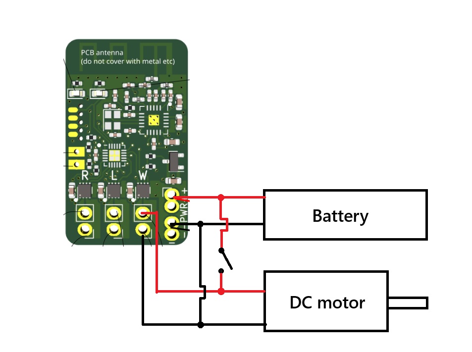
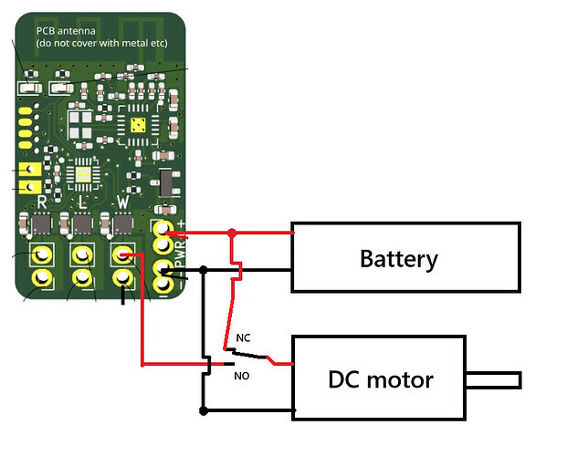
I ve drawn a schematics of the connection but I immidietaly realized that this will most likely turn my BBB Malenki into BBQ Malenki:
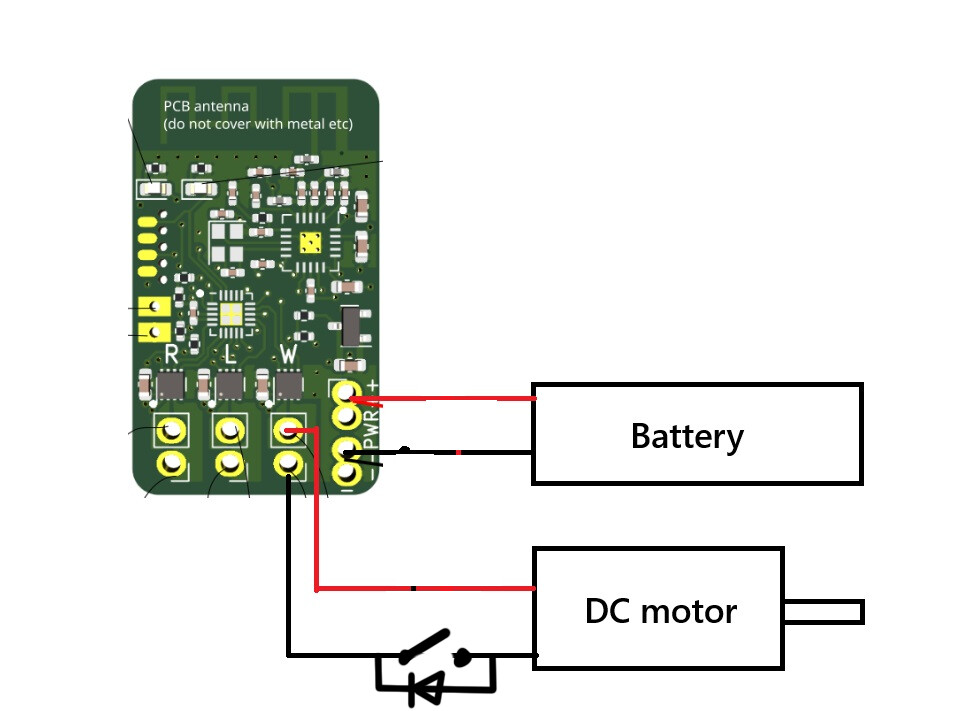
Sounds like you want to do a limit switch - to prevent the motor driving in the return direction when fully returned?
The easiest way to achieve that would be with a push to break switch and a diode in parallel. Position the push to break switch so that its depressed in the home position and wire the diode so current can still bypass it so that the motor can still fire in the opposite direction.
That being said this is all a complicated way of getting something that’ll be more complicated and less reliable, less featured (no actual positional control) and likely actually perform worse than a good quality servo.
High quality servos are absurdly power dense at this scale.
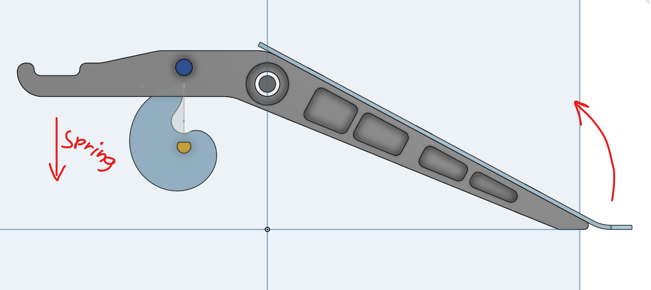
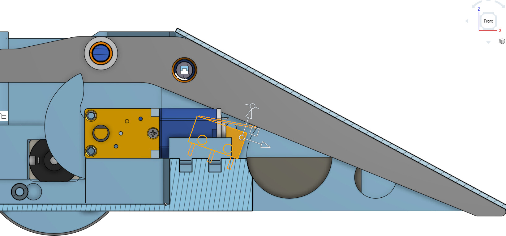
The idea is that the snail cam will return the flipper to it s initial position where it should stop and wait until i trigger it via transmitter. The flipping part is pre-tensioned by elastic band. Therefore the motor should spin only in one direction. Here s a sketch:
If i use your sketch, then once the switch is openned, i wont by able to move the motor anymore.
Servos might as well be a better choice as you suggested, i just want to experiment with this to see which solution packs the most punch. I think the stored energy of this mechanism might be quite powerful.
Yeah I was sharing a diagram for a limit switch - to stop overdriving., where you prevent it going too far in that direction - but still able to go in the other direction. Not what you need, which I can see now you’ve given a bit more context.
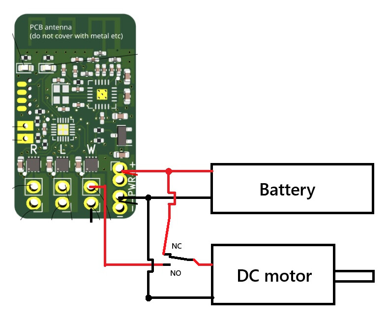
once the switch is triggered (flipper in ready position) it will flip to NO connection. But i am not sure if i can connect the negative terminal of the motor directly to battery as drawn above or use some sort of dual channel switch in order to change the connection of negative as well?
I don’t think you’re going to be able to get this to run “dumb” i.e. mechanically off the switch. Just thinking if that switch cuts the direction when depressed by the flipper arm - you’re never going to get it to budge and therefore unable to trigger the spring to fire the flipper to open the switch to turn the motor in the first place.
I can see some Arduino arse magic in your future
Though if you’re more mechanically minded I can see a few servos in your future. Peter Waller has some excellent examples.
I checked the drawings of malenki as well as the onboard driver DRV8837. Turned out its just a H-bridge using the battery voltage to directly feed the motor. (At least that s how i understood it with my poor knowledge) So I decided to allocate some money on my bank account for another Malenki nano purchase and soldered it together according the the schematics i posted earlier.
It worked (to my surprise, I must say) as intended. The motor spins untill the limit switch is pressed and once it stops, it can be put into motion again via transmitter. Ofcourse, now i am able to turn the motor in one direction only, but that is all i need.
edit: just to clarify, i meant this picture, not the first one