So, after having run Ursa Minor Alpha at Sceetles twice, I decided to give a custom build a shot: a shuffling, friction drive shell spinner. After a good number of months, I finally managed to get it to this point: https://www.youtube.com/watch?v=Wuma0Pl4XZE
It’s moving, it’s shuffling around and it’s under 600 grams, which means I’ve got a boat load of weight available to use for the weapon system. BUUUUUT this also leads to some… complications in terms of what to use.
With my weapon being a friction drive shell spinner, I obviously need enough power and speed in order to shift the weight to cause enough damage, so my initial thought would be the JCR-4935, but with it being an import, it might cost an arm and a leg, so I’m just wondering if there are any motors that you’d recommend instead?
For the weapon shaft, would a 20-22mm stainless steel shaft work? Or would that be slightly overkill?
And in terms of bearings, what would you recommend that I should use?
Any help with any or all topics would be fantastic.
The shaft sounds massive and would be on the larger end for featherweights.
I’m not much of a spinner builder, but thought the following may be useful…
The most active shell spinner in the UK at the moment is probably Paradigm Spin, Mark’s put some specs of his bot in the description of this vid:
and there’s a build log of the bot on his twitter hope that helps a bit
Thank you, I wanted to challenge myself instead of just recycling the SSP wheels, so with the advice from a certain Hull man, got a Bambulab A1 a couple years back and got into the 3d printing thing. It was my 4th attempt at the shuffling mechanism itself using TPU 95A, and I learnt that if I wanted to do plastic on plastic, silicone lubricant is my friend. Ran it straight for 2 minutes to test and no jamming what so ever.
And I’ve had a look at both the video and Mr Mellor’s twitter account to see what I can gleam from it, the first being that the motor he uses is just as expensive and… surprise surprise, is an American import as well, so… at this point, I might just take the plunge and get the JCR 4935 1000kv, along with the Pariah ESC (and a couple of spare Dartbox Dragon motors too.)
Unfortunately, despite digging into Mr Mellor’s twitter account to see what kind of shaft and bearings he uses, I couldn’t find the info to save my life… either that or I’m as blind as a bat with echolocation interference. But seeing as you said that 20-22mm would be on the more Featherweight side of things, would 10mm suffice instead? Or should I swap it from a shaft to a pipe with 2mm walls instead to keep the weight down?
Once again, any insight to any or all these topics would be fantastic.
Honestly the feet were experimental, but the fact that they run so smoothly, I’ll make more of them just in case I need (and I definitely will) replacements in the near future.
And I did notice that he uses a hollow shaft, with how his link comes up and underneath the little bobble self righting thingamy he has. It could come in handy in case an event decides that they don’t allow switches, so a hollow shaft might work… question is what size to go for?
And to those that see this and do make spinners… would the JCR-4935 1000kv be the best bet for a weapon like this? Especially as the one that Paradigm Spin uses is 600kv, though not battle prepped like the JCR, and the delivery/import tax cost’d probably be the same.
As someone running a 900g spinning mass beetle I love this build – and that shuffle is beautiful.
Motor wise I don’t see a reason why the jcr motor fundamentally wouldn’t work in your bot but its maybe not what I’d lock myself into off the bat – its probably around the right stator size you’d be looking for, if a little small given the potential 1.4kg?? weapon assembly you can afford if you want good spinup. To me when picking a motor for this build I would have thought the most important would be finding something that fits well geometrically in your bot and has a kv that hits the tipspeed you’re looking for. That may well be the jcr but it may also not be. With that motor you’re paying a lot for all the battle hardening and durability its designed for in weird loading scenarios – people mount spinners directly to it etc. With a friction shell, in theory you shouldn’t need as much since you should be able to shock isolate better but again it depends on design.
As far as shafts and bearings are concerned, yes 20mm is an absolute waste of weight. I think most of the uk spinners run 10mm hardened – some hollow. Potentially what might end up being more important is how you constrain the shaft to the chassis. With regards to bearings just pick some decent thickness deep groove and space them apart as much as you can.
Really looking forward to seeing how the design comes along with this what you have looks super promising.
Worth considering that even if you run a switch you still need to be positioning it in a way it’s easy to access in it’s normal orientation so you might want to run the switch in the shaft regardless. Worth seeing how some other robots tackle this. Wajoo has the switch in the shaft, while some bots like Vortex and other overheads opt for a switch under the path of the weapon, but where in the vast majority of cases the shell will stop without covering the switch.
I’ll take this one by one and see what solutions/thoughts I can come up with…
From Rhys’ comment:
Thank you very much, I appreciate it.
As for the motors in question, I’ll give it a shot, and if it doesn’t work, I can always try them on a different build… or crack out Ursa Minor Alpha for one more run around lol.
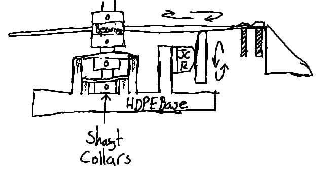
The shaft and bearing, I’ll give the 10mm hardened hollow shaft a shot. And it’ll more than likely be constrained to the chassis in a similar way to how Vortex’s shaft was secured to it, with shaft collars and the like.
Though it wouldn’t hurt to ask if there’s a place that you’d suggest I’d go to for both shaft and bearings.
For Craig:
I run the Just Cuz Robotics Mobo V2 from my old SSP kit, and it’s a solid piece of kit… unfortunately the only real way to get it to work is to have it screwed into the base of my bot, where the switch is facing downwards to the floor, so… unless that works, I’m going to have to figure out a way to solder the switch together and wire up a Fingertech switch through the shaft…
I might have to make a quick sketch on what I mean by all that, to make things easier for people to understand.
Quick edit: I forgot to say 20mm Diameter, though that’s still probably overkill, right?
unfortunately the power switch on the Just Cuz mobo isnt legal under the BBB rules legal currently. Only metric fingertech and Lynx switches are.
That being said there is nothing stopping you from using the mobo and just leaving the onboard switch in the on position and wiring a seperate switch or link in between the battery and mobo.
123 bearing is pretty good for showing you a range of bearings. I use the filters on there to determine what bearing I’d want to use and then take the name of what it spits out and buy from wherever. In terms of big hardened shafts I can’t be of much help because I’m a hubmotor guy.
Just out of interest, how are you making the shell?
Thank you for letting me know about that Jack, I appreciate that. And I don’t mind doing that as it’s what I had to do (with help from Ellis and the others) at SCeetles 2 with Ursa Minor Alpha the first time I competed.
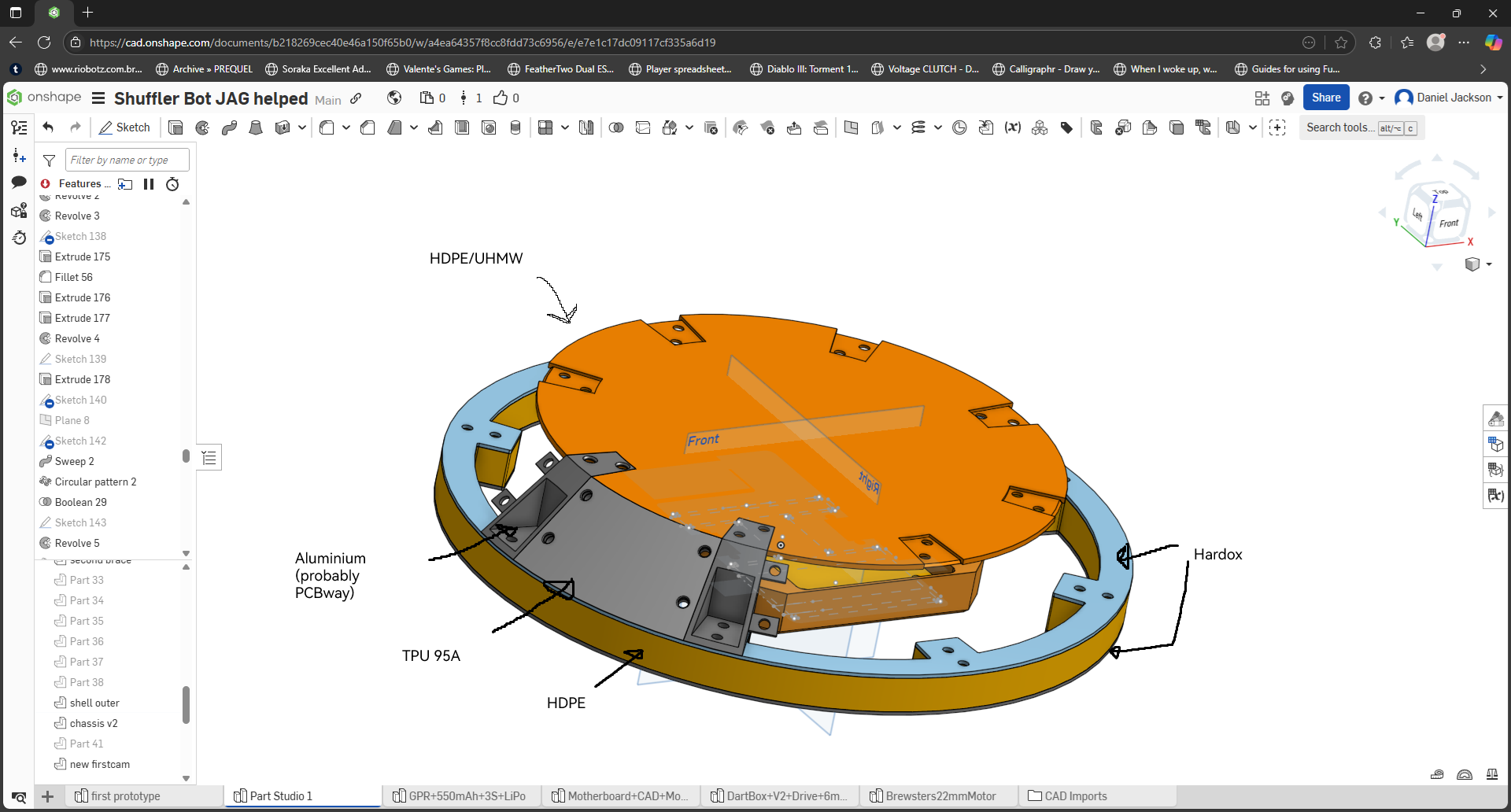
As for how I’m making the shell, all I’ve got is a general idea, like the basics of the shell of how I want it to look, I obviously need to make edits/redo things, but this is what I’m wishing to do for the shell:
It’s kind of wishful thinking right now, as it might just end up being… well, just a tube of HDPE with a lid and a pole through it with some teeth, but the idea is to not let vertical spinners have a good grab at it, kind of how Chonkiv from NHRL have their shell.
Just as an additional bit of info via a very quick and dirty Paint sketch (I know it’s crap, shh), this is the general idea of how I wish the inside’d look like. It’d be a separate entity from the actual chassis all together, so if one chassis gets completely demolished, I can just unscrew the base out from it, and swap it over to the next chassis in line.
And with it being friction drive, I’ll also have to learn how to make a wheel with some polyurethane mix so I can get the wheel to properly grip onto the shell.
And the way the shaft’ll be held into place is by taking the kind of thing that Vortex used, and putting some sturdy mild steel plates on top of those little protrusions on each side of the shaft, then attaching a shaft collar to the underside of them so that it doesn’t get pulled out.
This is such a dumb time to post this, but… my brain won’t let me not think about it, so here we go…
So, I want to upgrade from 3s (11.1v, 80C, 550 mAh) to 4s, but I’m still running the 2X 15A Budget ESC that came with the SSP kit, and I’m getting the 70A Pariah for the 1000kv motor… how big of a battery will I need to satisfy both ESCs without blowing everything up? Because right now, my head’s a stew, and I’m struggling to find answers with it as well.
Also, to be on the safe side, how big of a fuse would I be looking for too? Just so things don’t go boom.
The more important question is to make sure your ESCs support 4S or 4 * 4.2V = 16.8V (fully charged) and also the drive motors won’t draw too much current for the ESCs as the JustCuz brushed stuff can be quite intense in that department - so do double check that the SSP stuff runs out the box on 4S.
As an example if 80C is the burst rating of your 550mah lipo, the max discharge is 80 * 0.55 = 44A. The rules require your fuse to be below this max discharge, most people tend to go with a 30A fuse wire.
It’s virtually not going to happen that you’re drawing max current from all your ESCs at once, but I’m not a spinner builder, others may have some better input on lipo specs.
I did have that concern, and I did also notice that JustCuz dropped the 2x15 Budget ESC from their shop. Thankfully, Repeat has the exact same make and model (literally had to go grab it, put it up to the screen and closely inspected it all) so I was able to see what the limit in terms of S was listed as, which was 4S, and the Dartbox Dragons can be ran at 4S straight out of the box as well (says not recommended, but if I’m not mistaken, I can limit how fast I can make the motors go on my receiver to make sure they don’t go kaboom), though I will still be making a 30A fuse wire… fuse, between the battery and the switch, as you can never be too safe concerning everything.
But the input is still exceptionally helpful, Joe, thank you. And if anyone else has any input/advice on it, I’m all ears. (Insert get a doctor for me joke here)
So the motors came in and I’m more than happy with them, they look chonky as hell and they’ll definitely give .
But now the dilemma is about batteries, and as mentioned before, everything can be ran at 4s, but I don’t know how big the mAh and the C numbers should be in order for them to work, and I don’t exactly want to buy a battery and have it either run out mid way through a fight, or not have enough juice to turn on at all. Needs to be compact as well to make things fit a little easier and to make it a smaller target haha…
With that being said, to make things a little easier, the list of electronic and motors I have are:
2x15 Budget ESC
BBB Beetle Dual Brushed ESC (As a backup)
Dartbox Dragon Brushed Geared Motor x2 (plus 2 for backup)
Pariah 70A Brushless ESC (With a backup)
JCR-4975 1000kV Brushless Motor (plus 1 for backup)
As said before, I shall also be sticking a 30 amp fuse wire in between the battery and the switch (which I need to buy).
Now the question is… which size battery should I get and from where? Any advice with this’d be fantastic.
Edit: What connectors do people use for their brushless set ups? Bullet connectors or something else?
So, with Rhys’ advice, I got a bigger battery… though I decided to go a little more overkill and got a 930mAh 4s off of HobbyRC. Along with some fuse wire, more 14AWG wires and some MR30’s. On top of that, I figured I’d get myself a fingertech switch and another BBB Dual Brushed ESC as well.
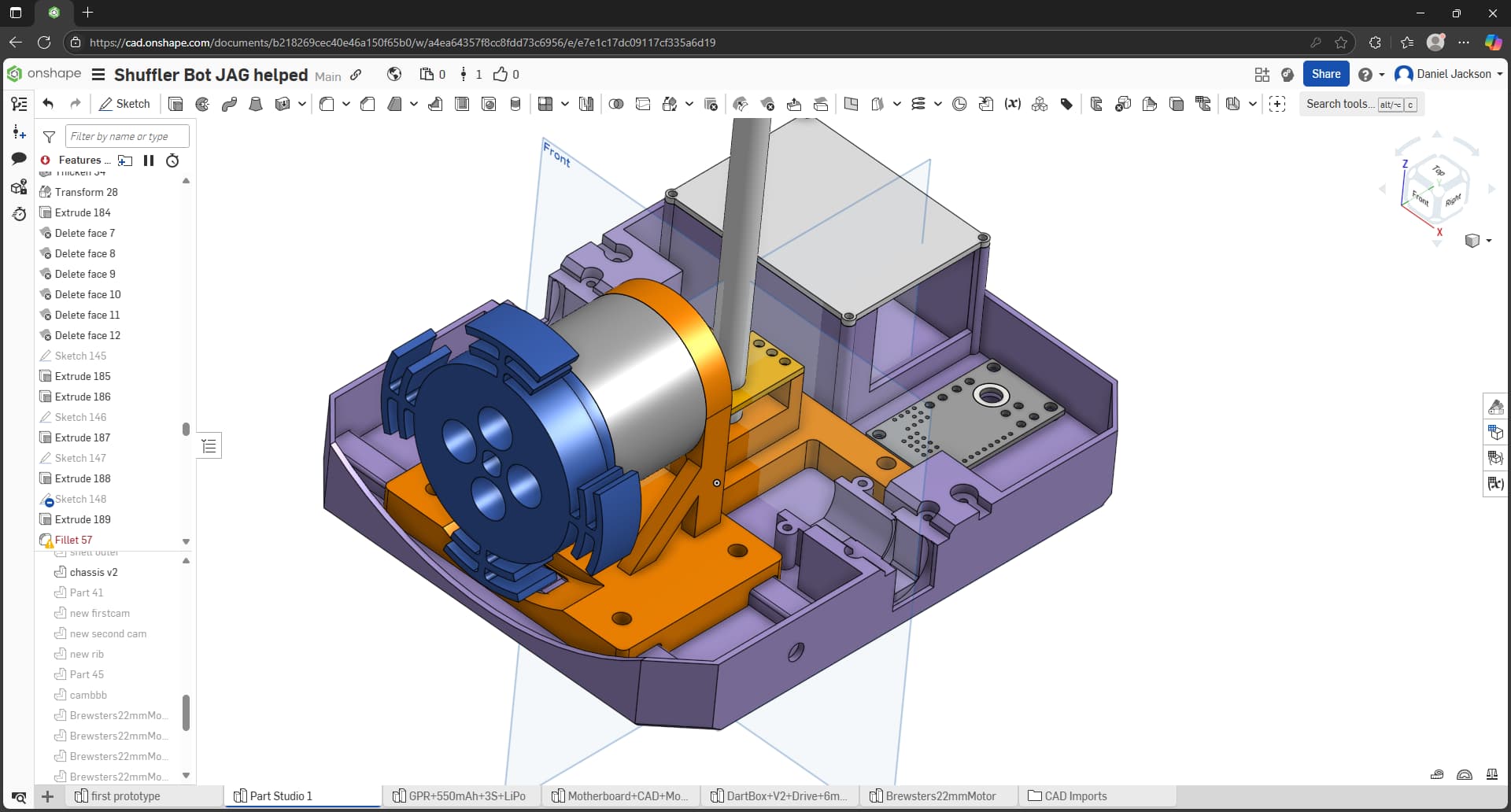
But this also means I needed to readjust the chassis once again, not only to accommodate the new battery, but to allow space for the wheel for the friction drive of the shell itself… those parts were the easy parts.
The harder part was to add new things and edit the weapons platform, to not only be able to mount the hollow 10mm x 2mm thickness hardened steel shaft, and to mount the JCR-4935.
Unfortunately, it looks like a complete monstrosity. I’ll either have to figure out a way to split it up into logical pieces so I can ask someone to cut it all out… or if someone can do the absolute impossible and cut it all out in one pie- ah who am I kidding, I’m gonna have to split it all up to pieces, which will be a pain in the backside…
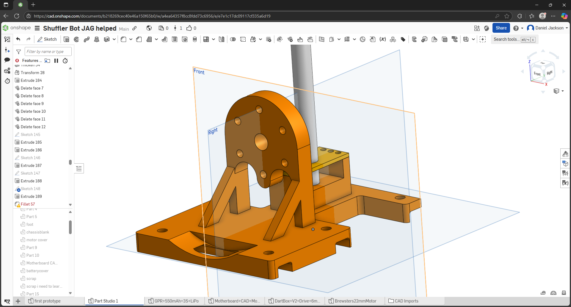
Looking at that huge bracket might it not be easier to mount the motor upright instead of at 90 degrees? Surely driving the shell from the ID instead of pressing the motor into the top plate would be more robust and much less mechanically complex
That’s what I initially thought of too, but it’s the wheel that’s connected to the top plate rather than the motor itself… unless that’s what you meant and I’m a colossal idiot. The idea is that the shell’ll be friction driven. Think ChonkIV from NHRL, but built by a complete idiot.
But as I said, I can probably split it up into a few pieces, maybe try to engineer it to be a slot in construction, with a couple of bolts and some dowel nuts to make things nice and secure possibly. It’s all a work in progress right now, it’s not all set in stone… or plastic in this case right now.