I meant mounting the motor in the same plane as the shell. You could still keep it friction driven. I just don’t see much point in introducing all that weight and more potential failure points in that bracket to turn the motor sideways unless its for some kind of packaging constraint
1 Like
Oh, I see what you mean now. Yeah I understand where you’re coming from with this, but it’s more to do with how I want the shell to end up looking like. I did say in the past that if push comes to shove, I’ll make it more cylindrical, but I really wish to give it the sloped sides kind of like how you see some of the big spinners out there.
That’s not to say that I didn’t think about it in the past though.
There are a couple of ways that it could possibly fail however, with both mounting the motor horizontally and vertically.
When mounting it horizontal:
- It could be more susceptible to undercutting attacks or attacks to it if the robot is upside down, which in turn could potentially damage said motor, unless I add some decent thickness to the underside of it, which’d be more weight.
- If the shell were to follow the dotted line down to be a true cylindrical shape, instead of being more of a traditional, angle sided shell, a la ChonkIV or Gigabyte, then all it could take is a solid shot to the side to make the wheel’s pathing unsmooth, and in turn put either massive amounts of stress on the motor, or stop the motor completely and burn out components. A simple way of combatting that would be to put it on some kind of horizontal suspension system, but that’d mean more moving parts.
- The original shell idea was to make it so that some sort of lip would come down to meet the wheel so it would spin, but even if it was to do that, the option here was to either to bolt a cylinder to the top plate of the spinner to create that lip, which, although could work, is a lot of precision work, which is not exactly my forté, especially when drilling things, or to go the way of Paradigm Spin and mill it all out of a single block of HDPE… which I can’t do because I don’t have a CNC machine, and, unless I’m wrong, would cost an arm, a leg and possibly three extra fingers. (please correct me if I’m wrong with that) This point can also be applied to the vertical mounting as well, just without the lip part of the point.
That’s not to say that there’re positives to that:
- As you’ve mentioned, it’d be less weight to put into supporting the motor itself, and less mechanical connections for it to possibly fail.
- It’d end up being a lower bot in terms of height, which would mean a slightly lower centre of gravity too.
In terms of mounting it vertical:
- More mechanical connections to put to making the motor itself vertical, which in turn gives it more chances to fail in terms of falling apart (as you mentioned before)
- Increased weight (once again, as you mentioned) to make the motor vertical in the first place as well.
- If a shot from a vertical spinner would somehow bend the shell, or bend the weapon shaft, then the wheel would no longer be in contact with the top panel of the shell, which in turn would mean no weapon full stop.
- The overall height of the robot would be higher too than if I were to mount the motor horizontally.
That being said:
- With the motor being suspended off the chassis itself, it protects the motor from weapons such as undercutters and vertical spinners if they were to get a bite into the bottom of the chassis, thus saving it from potential damage.
- The wheel would end up being run off the top panel of the shell, rather than having to implement a lip or wall for the wheel to run off of.
All in all, it’s a mix of logistics versus idea. Having said that, I don’t exactly know of the prices of CNC, so if there was the possibility of having a single piece shell made on the cheap, then the idea of having a horizontal mounted motor doesn’t sound too bad. But for now, my best bet is probably to have it vertically mounted, as it all can come down to the shell itself.
If any of this sounds confusing, then point it out and I’ll try my darnedest to clear up any confusion, dyslexia’s a pain in the posterior, and I struggle with putting sentences together in a way that I and other people can understand it.
I wonder if you’re going to have to spend a lot of time problem solving and making compromises if you keep down the friction route.
Was there a particular reason you’re hesitant to drive the shell with belts or gears?
Right now, it’s all the shell that’s making it difficult. As I’ve said, if there was a way to make it out of a single piece of HDPE without it costing a lot of dosh, then I’d love to know, otherwise I’d have to compromise and give up on the angle sided shell and go for the cylindrical shell instead, that’s the position that’s in right now.
Honestly, good question, and although this is going to sound like I’m being overly superstitious with it, but…
With belts, it’s the idea of them snapping halfway through a match and it’s just a shuffling rolling mess of me panicking and the like, or, and this can be applied to gears too, the teeth just shredding when I try to spin them up, or they do a Skrap, and on impact, the gear pops off the motor.
You could probably get away with hdpe or solid tpu gears with chunky teeth which would dissipate shock the same as a tyre. Honestly though I think a shell spinner is a complex design and theres a lot of different ways to go about implementing it. Your reasoning is sound so I’d say just build it and learn.
In terms of cnc I know a lot use ~£150 3018 machines or similar. Obviously a lot for a one off part but if youre churning out chassis’ on the regular definitely a worthwhile investment.
Ahoy! Builder of Skrap here. So, the gear flying off in the first fight was actually down to one simple reason.
I forgot to bolt it to the motor can.
Which to be honest was a me problem more than a bot problem. Every subsequent fight the motor gear was fine!
So the gears are 15mm Overture TPU with a fairly large mod and they held up fairly well under normal load, the only times I started to see problems with chewy gears were when the shell started to rise up the central shaft and misalignments started happening.
I’ve got a couple of HDPE gears I want to try so may give them, a go in the future but I still think gears in general are as good way to go ![]()
Well, before I can even think about mounting the motor to anything, I still need to get a final design on the shell. And technically, I have 3 options here.
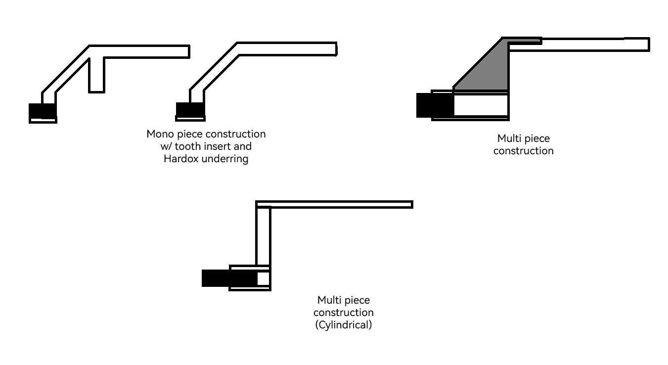
So, first would be the mono piece construction with a tooth insert and a Hardox under ring to hold it in place. It would probably be the lightest of all 3 options by a mile. The only problem is I’m not sure how much it would cost to get it all machined/CNC’d, especially as at the widest part, it would have to be 40 cm+ wide in order to clear the chassis completely. I put both the Horizontal and Vertical mount variants of said shell in because both versions could be possible with this construction. Only question is where I could find a cheap enough solution/service to make this a reality if I were to go this way.
Second option would be the option I thought about for a while, a multi piece construction where there would be brackets holding the top panel to the bottom piece, and between the brackets would be TPU 95A pieces to cover the gaps, and a ring of HDPE or UHMW sandwiched between two Hardox pieces, with extensions in two places to hold the weapon teeth. But, once again, I wouldn’t know where to start to look for these particular brackets, so this one is probably the biggest long shot.
The final option, which is more or less the most realistic, yet least desired version, is the cylindrical multi piece construction, with the same sandwich piece for the teeth to the bracket multi piece. This would probably be the cheapest way, but I don’t trust my drilling accuracy into a cylindrical piece of HDPE or UHMW unless I get it pre drilled via a service or something… EDIT: It’s probably going to have to be pieces put together in a fashion to make a circle and stack them up to make the cylindrical shape… Unless, once again, someone can lead me the right way.
Now, out of these three options, which one would be most viable, and depending on that, where would be the cheapest and good quality place to get it done from? I know it’s a weird question and all, but in order to get one thing done, another has to be designed and done first and it’s a bit of a sh*tshow mentally. Any help would be fantastic.
EDIT No2: So I may have come up with a solution… and it was staring me in the face the entire time, and I can’t believe I’ve not noticed it until now. I shall make a new post in a moment about my solution.
So, before falling asleep last night, and wanting to just faceplant my desk for even thinking about looking up some prices for the big ol’ HDPE tubes, I looked over to my Bambulab A1, then back to a previous comment made by Rhys about the CNC machines… and then it hit me… I could split the cylindrical part of the shell in the first multipiece construction design into 4 even pieces, and just bolt them together, and possibly buy a CNC machine so I can cut out other pieces that I need…
Insert gif of Forrest Gump saying “I’m not a smart man” here.
This is borderline featherweight territory. Paradigm Spin is probably in the 250mm zone for a plastic FBS. Weight and structure would be a concern.
I think you’re on the right track with the single piece shell and the hardox ring. I think you could get that done for a couple hundred, potentially less with the right shady Chinese machine shop. You’re going to need to work out your attachment method to get the ring to the plastic. Quite a lot of inserts or interlocking geometry will help because otherwise
Printing a shell in 3/4 pieces would certainly be the most cost effective. Really rigid TPU or a nylon I could see working pretty well. I would lean heavily on mechanical interlocking between the shell sections and potentially solvent bonding them together if going down the TPU route. I can see it working with a thicker aluminium top and hardox ring tooth locking them together.
Personally I would be treating it a bit like a consumable and have 2/3 spare plastic shells ready to hot swap
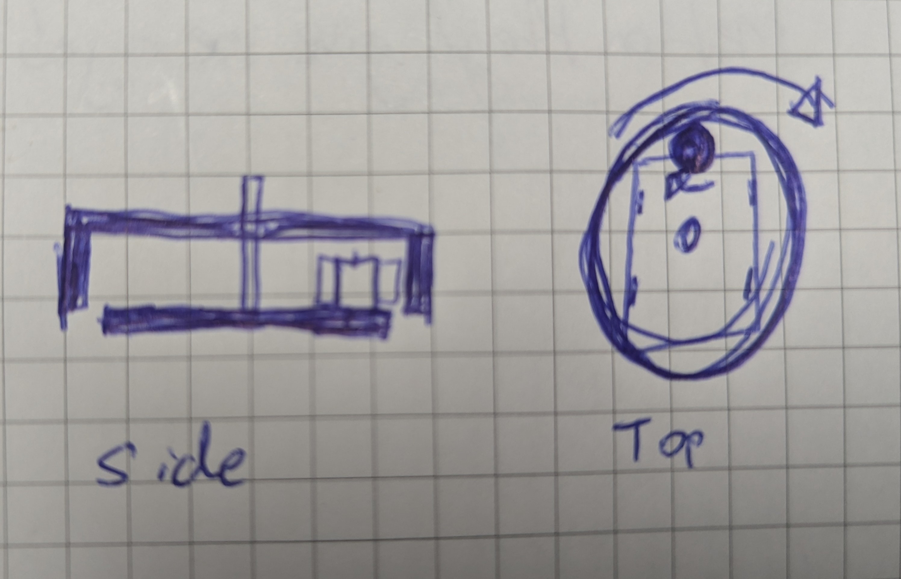
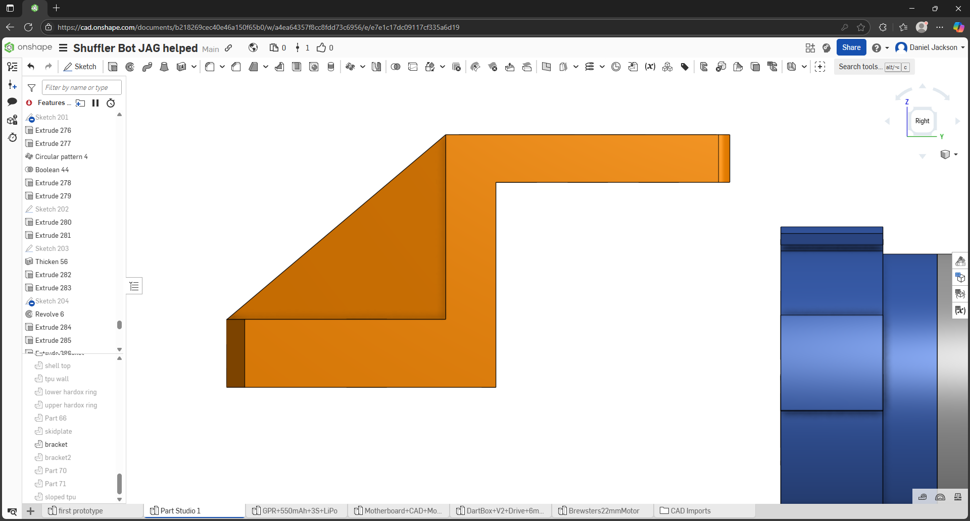
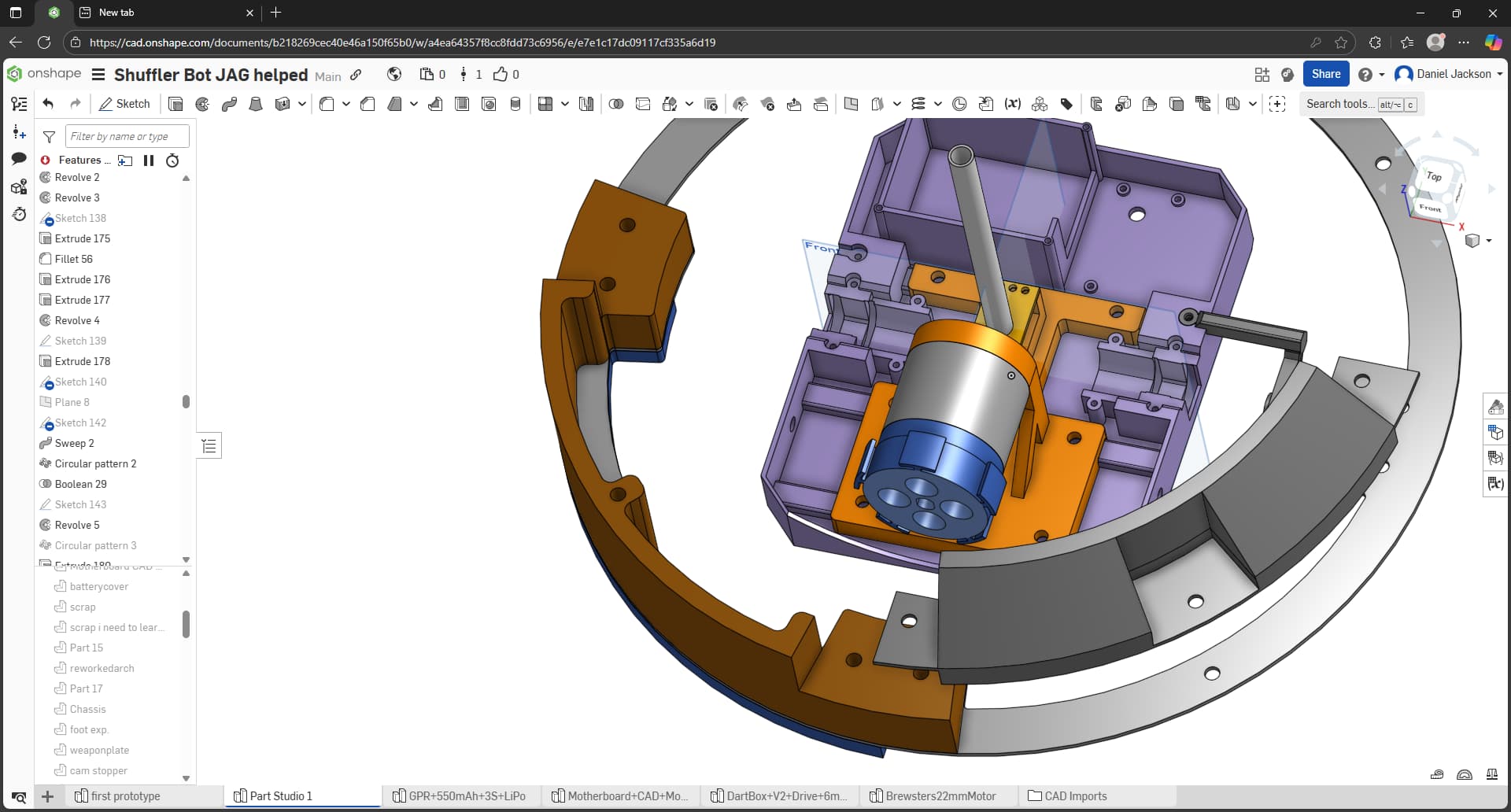
After a little more shell design revising, this is what I’m up to at this current point in time. (please note, the current diameter is now 350mm rather than the absurd 400+. It’s still large, but it’s smaller than it was before.)
The idea is to print four of the brown pieces in TPU 95A with a fairly high wall count and a decent amount of infill in order to make it as structurally sound as possible, and be able to flip two pieces over so that they connect in a way that when a bolt gets put through them, they lock in place and gets sandwiched between the two hardox disc plates (weapon teeth still in design phase right now.)
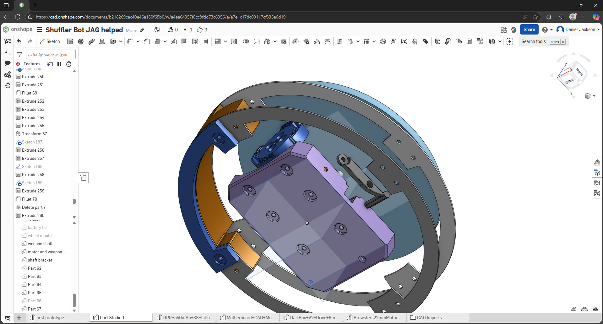
The dark blue section (the skidplating) underneath will also be made out of four pieces, but cut out of HDPE (if I were to make a splash and buy myself a Genmitsu 3018-Pro… or find a hackspace that’ll do it for me… or get them ordered to cut.), and in a way that they don’t interlock, so that if one piece gets knackered, I can just unbolt it, and replace it.
Now the problem I’ve been scratching my head at for the past… 6 hours roughly, despite modelling one out and realising “crap, would this even be possible to be cut out or constructed?” is how on earth am I going to make brackets to connect to the shell top itself?
I did quick rough sketches of a couple of ideas, but they all lead to the same question… how on earth am I going to get these made? Bearing in mind that the (parallel) gap between the top face of the top hardox plate and the top face of the top panel of the shell is 50.066mm (specific, I know, but it’s one of the reasons why I like onshape). I also have to bear in mind that it has to clear the edges of the wheel that drives the shell too.
But as far of a redesign goes… it’s not too bad… so far at least. Just need advice or a helping hand with the brackets in general.
love to see more shell spinners so been enjoying your progress so far, ive only ever built 1 at a different weight class so take my opinions with a grain of salt
firstly perhaps its the perspective but the wheel you have for the friction drive looks gigantic in comparison to the motor, since you really don’t need that much clearance between the top of the shell and the top of the motor given that will have to be stiff if you want to create friction in the first place. shrinking that wheel would save you some hight and would make making the shell easier since it wouldn’t need to be as tall. even if you could take 5mm off the hight of the shell it would make it much easier to make stiff esp if you printing it. plus the stiffer your wheel for the friction drive id imagine the easier it will get a good connection, smaller would make it stiffer. although ive never build anything with a friction drive so i could be talking rubbish
and not trying to dissuade you from a friction drive solution since it has its benefits but feel for smaller weight classes its kinda redundant when gears can take the impacts. I run a gearset in my 12lb shell spinner with no clutch and so far have had no issues with it.
in regards to making the shell i wonder if you couldnt make it from a section of hdpe pipe? you woudlnt be able to have the angled features as easily but would make the shell allot stiffer than printed plastic id imagine with allot less machining involved
just my 2 cents. looking forward to seeing how the deisgn evolves
1 Like
Thank you very much, I’m glad to hear that, that’s genuinely a great thing to hear, and I’ll try my best to let you know why I went for these decisions in my design plans.
You would both be correct… and correct. What I forgot to take into consideration was the distance the edge of the wheel from the centre of the robot itself, which is roughly 187mm… which would make it… well over the theoretical tip speed limit. And the smallest size wheel I can go without having to compromise on the design is 60mm diameter, which, at the same distance, would make it 217mph theoretical. And 70 would make it 250mph. It also means I can drop the top shell down by 10mm if I go for the 70mm, and 15mm if I go to 60mm. So thanks for pointing that out, that would’ve been disastrous if you didn’t haha. (I’ll more than likely go for the 60mm variant to be safest.)
Now I did mention why I don’t want to run a gear system is that, although HDPE can be very useful, I’d end up shredding the gear teeth, knowing my luck, so it’s more superstition than anything, but it’s also me trying to be as safe as possible.
Now I did try to explore this option… but despite looking, I can’t find 300mm HDPE pipe, and the sizes that I do find are in the £300 range, which is… kind of ridiculous in terms of price, whereas with the TPU I have, I can print out replaceable pieces rather than having to swap out the entire piece of pipe as well, so not only is it using what I have, it’s a maintenance side of things too.
But I’m both thankful for the advice, and the opinions too.
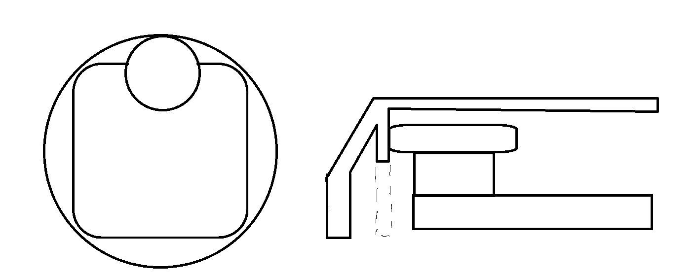
EDIT: After a little more work, from the side, this is what it looks like now.
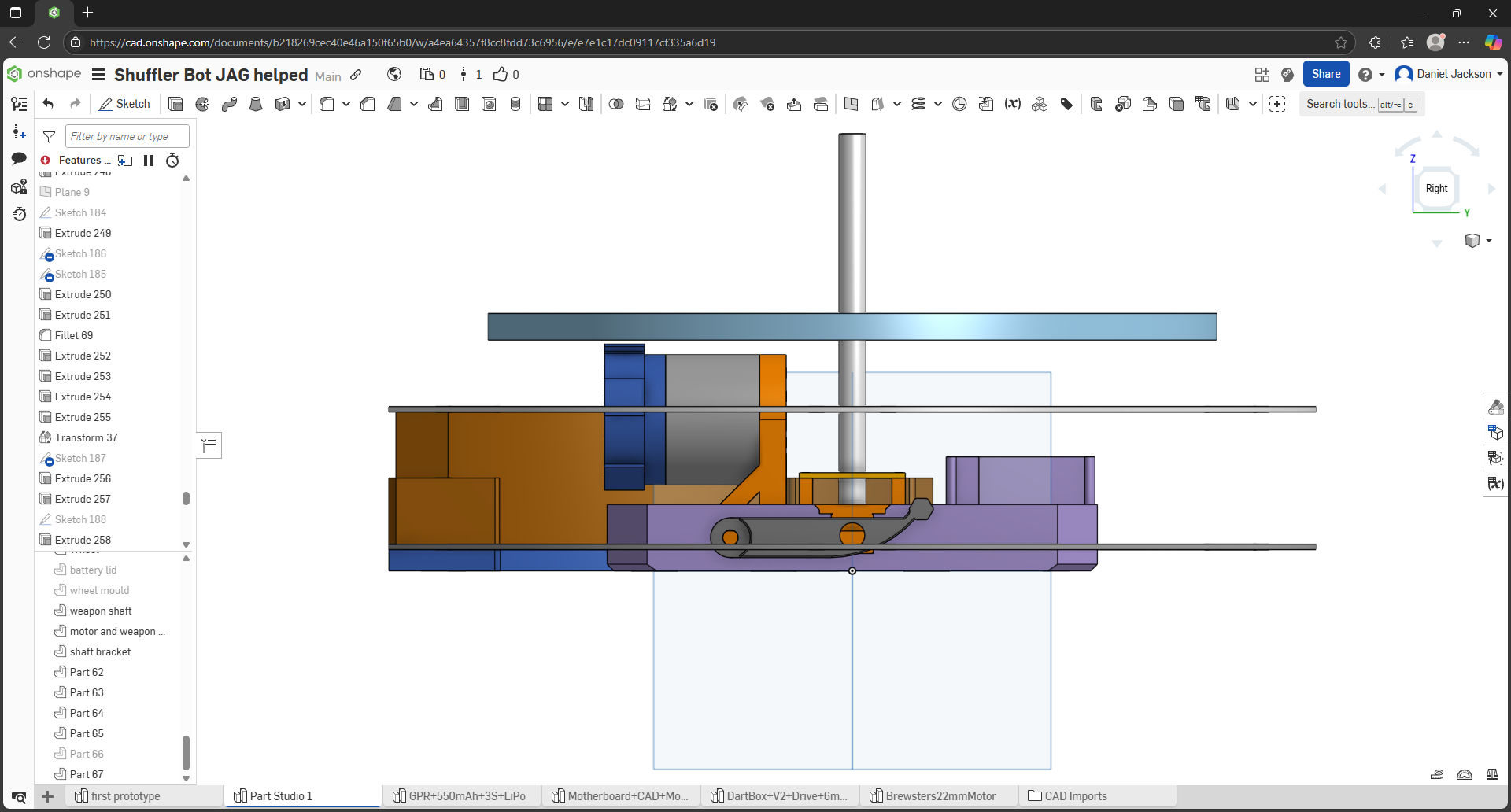
The top is a lot lower now, with a 25.166mm distance between top plate and the upper hardox ring, though the question still remains… how would I go about connecting the two together?
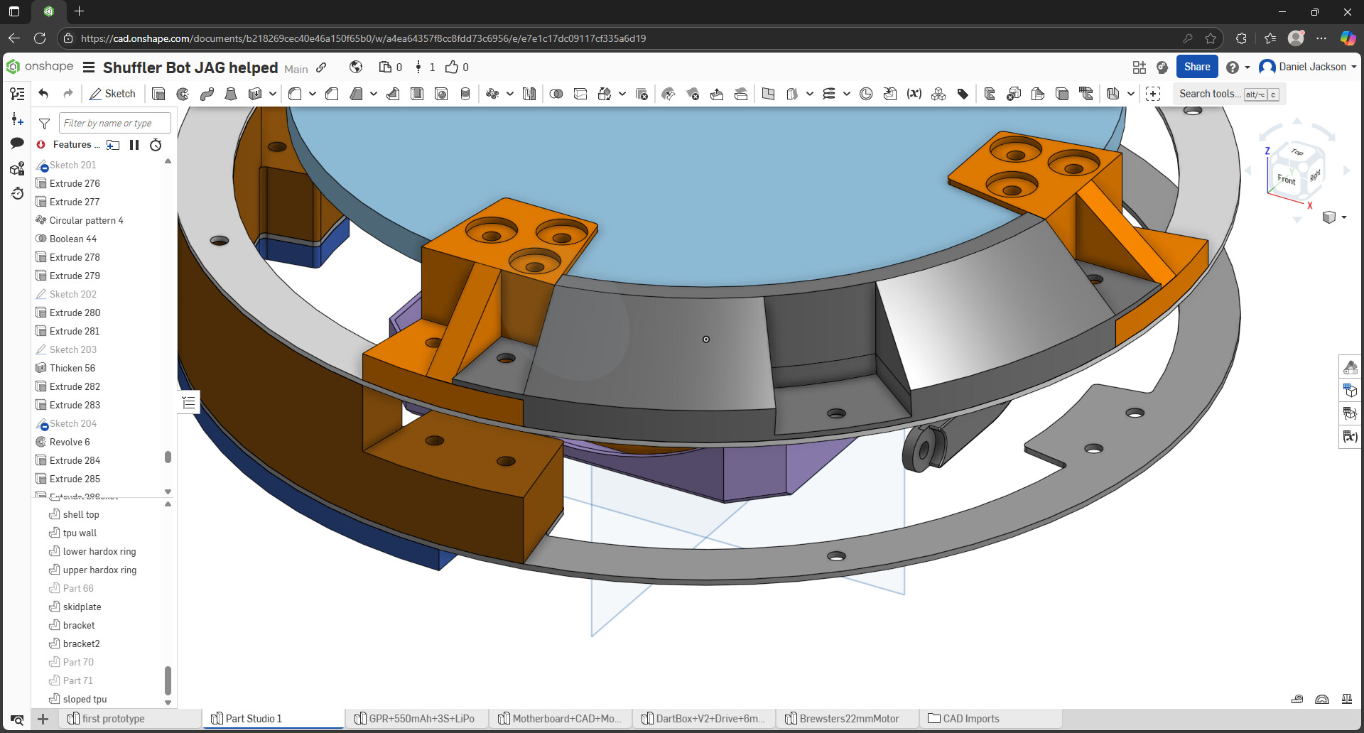
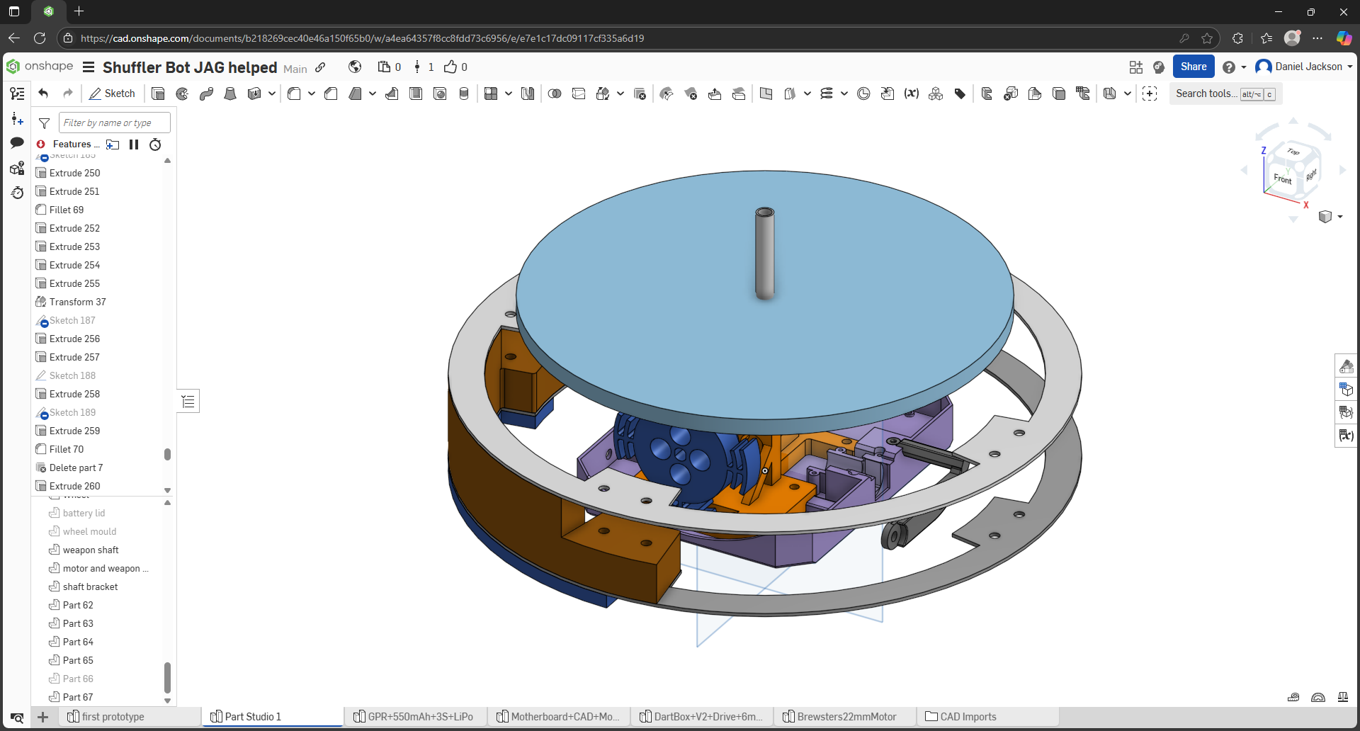
Okay, this is the solution I’ve come up with, with HDPE supports to hold the rings to the HDPE top plate, with some TPU sloped sections that can be bolted onto the supports and top hardox ring too.
Unfortunately, I don’t exactly have the space in the flat to get a CNC machine, so I’ll more than likely have to get it outsourced, along with the top plate.
The question is… would this even be physically possible to CNC out of HDPE? The orange brace that is, ignore the wheel on the motor blank to the right. If so, I can get to separating the motor and shaft mounts into pieces that can jigsaw and bolt together.
As it’s drawn exactly there - no. With a corner rad in there somewhere on the triangulation, sure. Couple setups but it’s pretty straightforward
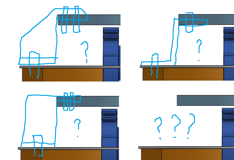
My brain must be short circuiting, because I don’t understand. Is there any chance you can show how? Doesn’t have to be fancy, just showing me in a paint png or something like that’d help.
Edit: Did you mean reducing the size of that triangular support piece?
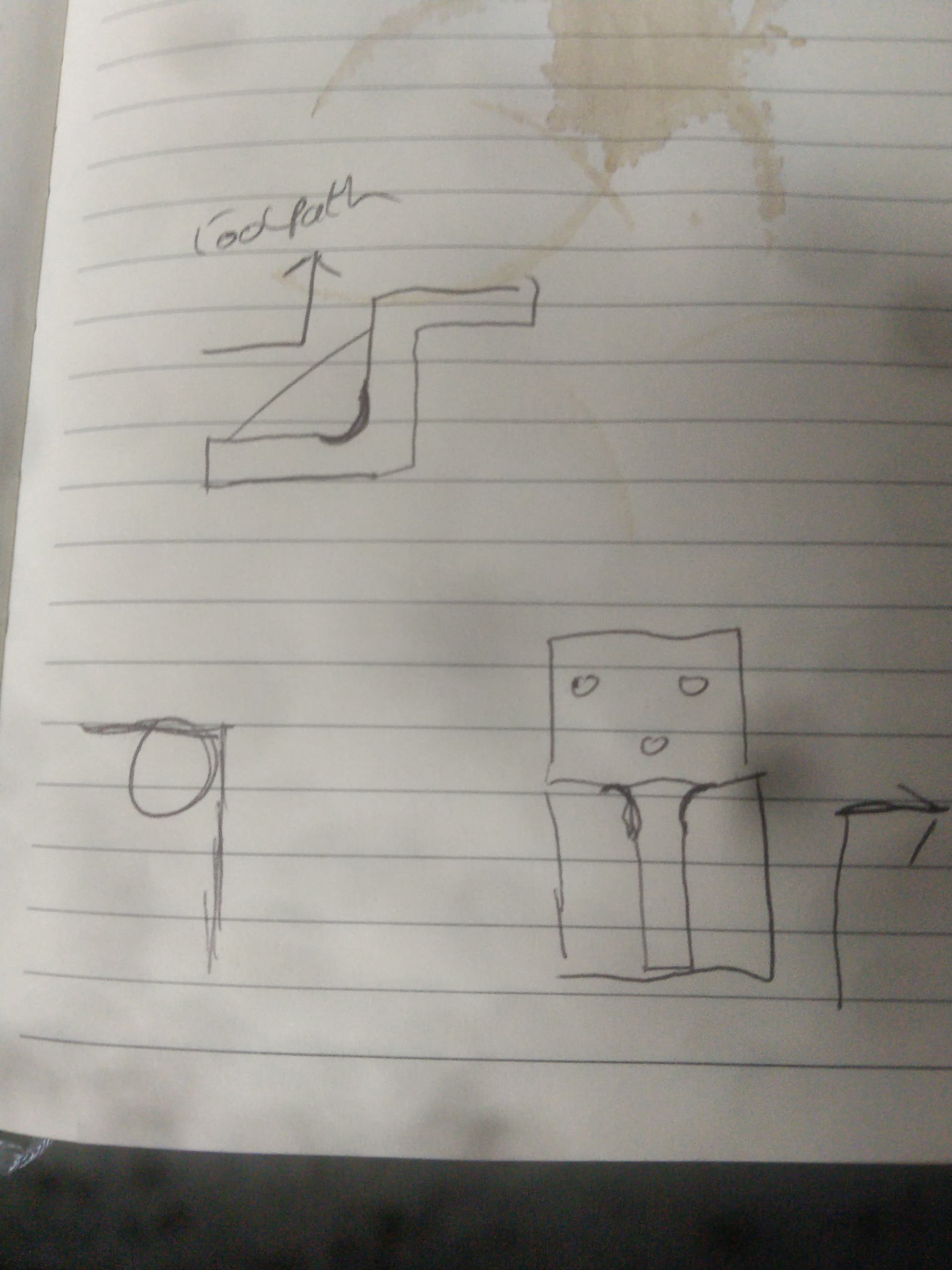
You’ll regret asking that - crude sketch attached.
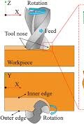
Think about how it’s machined with a circular tool (endmil for example) which can only make a perpendicular edge in one axis at a time.
Now I’ve thought about it you could make the part with all the sharp corners but it would require a few setups and there would be no benefit to be doing it. Plus it’s weaker.
Less vital for softer plastics but whenever there is a sharp corner that’s where things start to tear. A nice thick radius in the corner is super strong (as well as being nicer to machine)
Worth noting when you get to tooth design too!
Mate, it can’t be as bad as mine. And sometimes the best things come from crude sketches. But now that you’ve pointed it out, I completely understand and it should be a simple fix in OnShape.
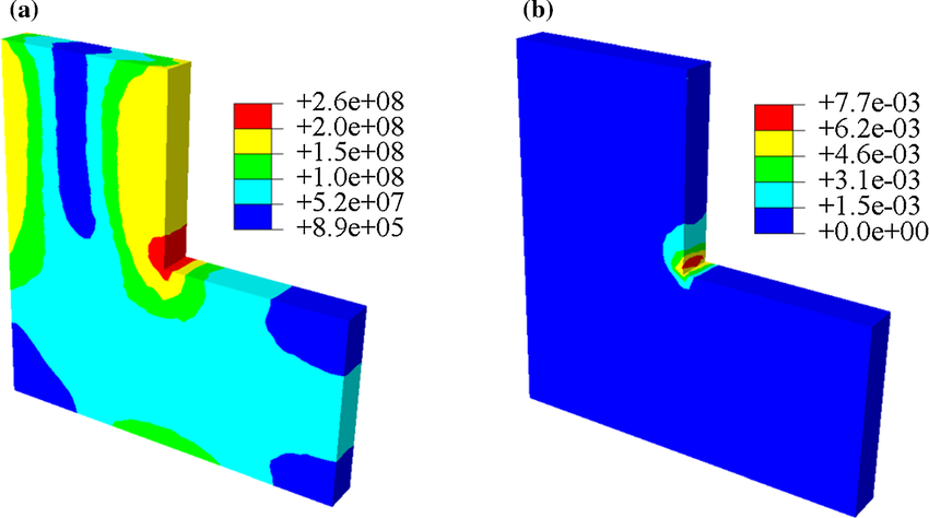
As for tooth design, the funny thing is, when I thought about the teeth, I pictured it in my mind to include the softer corner radius where it’s needed like in the demonstration picture of the stresses in the material you posted. Why my mind didn’t link the two together, I have no idea, but you’d also think with how much I’ve watched Forged in Fire, and how many blade breakages due to stress risers I’ve seen on that show, it’d somehow link up haha.
Okay, so I’ve done a couple of print experiments for the shell to create the TPU ring between the two hardox rings, and I managed to get each segment down to roughly 110 grams each, which looks like this:
Which is probably the best I’m going to get right now, as any thinner runs the risk of layer shifting, and thicker would increase the weight, so not bad going, I guess.
Now, I know I asked where people’d get their bearings from before, though more suggestions wouldn’t hurt, but the other question is what kind of bearing would be best for this? Deep groove? Needle roller bearings? I could really do with a push in the right direction in terms of this.
And in terms of the shaft… would this be any good? 10mm diameter and all that jazz.
1 Like
I wouldn’t expect that toolstation railing steel to be up to much. If you have access to a lathe putting a hole through the middle of a high tensile M10 bolt isn’t too tricky. If you don’t, I believe some of the spinner builders use industrial hollow shafts, I’ve seen them sold by RS, mcmastercarr, Misumi etc for building custom gearboxes, but here’s something similar on aliexpress advertised as CNC guide rails: 12mm 16mm 20mm 10mm hollow linear shaft 300 400 500mm inner hole 6mm 10mm 12mm harden chromed linear motion shaft rod CNC parts - AliExpress 13
As for bearings, I typically pick mine up cheap on aliexpress with the assumption they’ll end up rolling around all over the arena at some point. I’m not sure what flavour works best, I can’t tell where they mount on your design - are they all on the centre shaft or are you intending to have some on the outside of the chassis to stabilise the ring? Either way I would recommend picking something cheap (ie standard deep groove ball bearings), because it hurts less when they explode everywhere, and you’ll probably change the design and iterate away from whatever you pick anyway.
Honestly, reading AliExpress being used doesn’t give me much confidence, seeming as I’ve heard a few horror stories of the site having some less than par items in terms of safety and the like. And I’m hoping that the outer diameter of the shaft’d be 10mm rather than inner.
As for where the bearings’ll be, they’ll be on the shaft itself. Maybe inset inside the top panel of the shell itself to give it a more secure fixture. Though having said that, would standard deep groove ball bearings be able to withstand high energy impacts without shattering? That’s my biggest concern with that.