Part 1: The Backstory
This all started about a year ago in the wonderful game of scrap mechanic. A few of us had gotten together to do a speed build competition, having only 10 minutes to make a robot and battle with it. Since this was in a game and the real world rules of cost etc were not present, I decided to try and make something irregular, funny and just plain dumb. My idea was to make people believe I was making a simple 4wd vert when in reality it was nothing similar to any other robot in recent history. Reminded of the robot snake and of just snakes in general, I set out to build a robot with all wheels in nearly a single line. Where its only turning would be by bending the whole body. It did not work very well, would constantly fall over and was practically useless. But that wasn’t the goal. It was the funniest thing I had ever driven, and later that week I made a new version in the game.
This one was a lot closer to reality than the first and looked a lot better, and for the next few weeks I thought about how funny it would be to have this in real life and to see it wibble around the arena doing 3 point turns. But how would I do this? The only weight divisions I have any experience in are ants and feathers and ants would be too hard on weight, feathers too heavy on my bank account and also no where to take it. If only there was a class between the 2…
Part 2: Beetle Time
I’ve wanted to build a beetle for a very long time, but something has always just gotten in the way. Most recently it’s been the amount of time and money being spent on the CATaclysm to get it working to its full potential. However now that Xr no longer does FW, it’s almost become a lost cause. That isn’t the only reason I haven’t built a beetle until now though. The main reason has actually been that i’ve been too worried about making something unique and new that i feel like making nothing than something someone else has made before. It’s a mental block and not an ideal one at that, but when I started realizing that the snake may not be impossible to make in real life, it gave me what I had been looking for. Something unique and funny enough that hopefully will make people laugh or just look at and go “why?”
Building a beetle was a new experience and right from the start I knew that while I wanted to make a really funny robot, I would be making something more generic in the future. Because of this I decided to go with the most normal set of components I could to allow me to use them for future projects, this included using 22mms for drive and something small for the weapon. The weapon on this robot was never intended to be something scary and only so I could call it a 4wd vert, hence why I opted to use a 2205 for the weapon after the success of bots with smaller weapons such as toxin and tweedy’s hammersaw. The turning is something we will come onto later but ended up being a servo I bought for use in a bodgebot that just happened to fit the space I needed.
While the component choice was relatively simple with the ease of use of BBB, the robot really started to get complex when it comes to the chassis and how this will even work…
Part 3: What have i gotten into
The design is the most challenging part of this build, while most robots have 1 compartment to shove all the electronics into, I would be having to space these along a bendy and long snake. The first initial rough cad was designed on the 23rd of february this year and looked like the following,
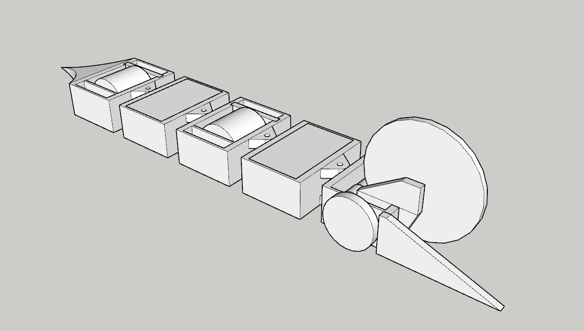
This initial design had 5 pods, with the wheels sitting exactly in line with the center of the bot. The 2 non wheeled pods were for the battery, and the servo and rest of the electronics. Each drive pod had small channels either side of the wheel to allow wires to go past and between pods. This 5 pod version was only a prototype and ended up being about 700mm long, while it was never made, 2 test pods were made to verify if the turning would work in the first place.
Ah yes, turning. Unlike everyone else who is smart, this robot cannot turn using variations of the left and right wheels, since they are all in a line. This means I had to create a way of turning that hadnt really been explored before. The idea I settled on came based on mechanical hands oddly enough. Most toy or DIY hands use a system of wire or string and a pivot to cause a curling motion and a moment around the pivot as shown below
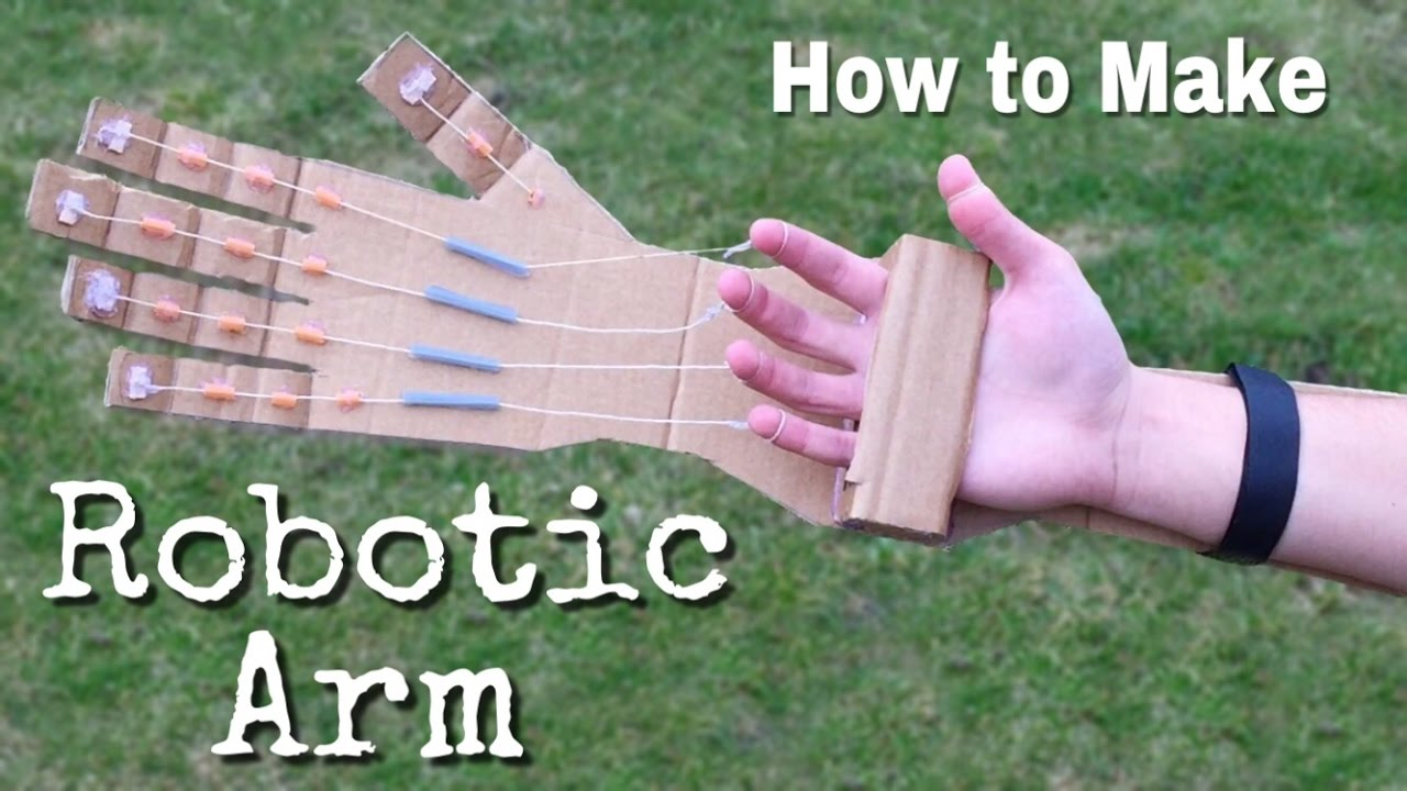
This seemed like a good idea, so I added some holes along the outside of the pods and added a servo with an extended horn to allow it to pull on one side and release on the other.
This PLA test version included 2 pods, one which was a stripped down wheel pod and the other being the servo pod. As the servo tuned one way it would pull on the string and therefore make it effectively shorter. This would end up pulling the other pod about the center and turning that way since the string was attached to the end of each pod. This test was with 2 pods to test if the theory would work, and while it did for now, the lack of testing with more pods would soon come back to bite me…
After a few months absent from the design of the snake to focus on a levels, I came back to this with a fresh mindset. While in a discord call with Sion he suggested to me to try and make each pod independant, this would be both funny if they were all split and would also mean that I would not have to have wires between the pods. This was also a similar time i realized that maybe having 5 pods, each about 150g in chassis alone would not leave me much weight for anything else. And this is where the fun really begins. My goal was now to fit the components I had planned to fit into 5 pods, into 3 smaller pods. The pods would not be completely independent due to batteries not existing small enough and instead would have a front independent pod and a connected rear 2.
Part 4: Rear wheels
The rear wheels posed a difficult challenge in this build. What I was dealing with was a long and skinny 22mm motor I had to fit into a chassis that could be tall but not wide. A slight issue. I also wanted a wide wheel to provide enough grip for turning and for pushing if it came to it, and to also honor the original scrap mechanic version. Once again I was left with constraints that are very unlikely to come up in normal robot building. Most robots are one of direct driving, belt or gear driving in beetles and I had to decide what would fit my use case the best. But quickly decided that gears and belts would make the wheel smaller and cause the chassis to possibly sag at the axis points if the wheels were not in the center of each pod. This meant I decided to pick direct drive. This came with other problems though. If I want a wide wheel but not a wide robot, how do I get a motor and wheel in that size? Simple, put the motor inside the wheel. This turned into the following design:
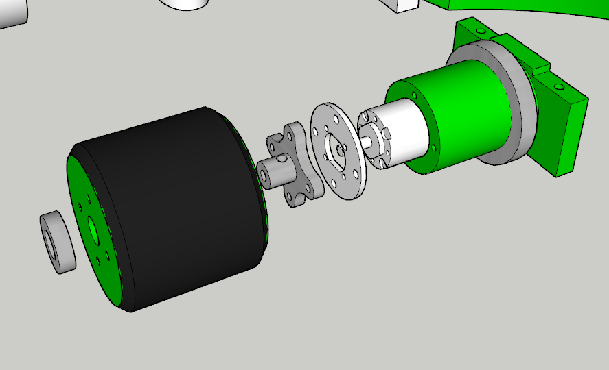
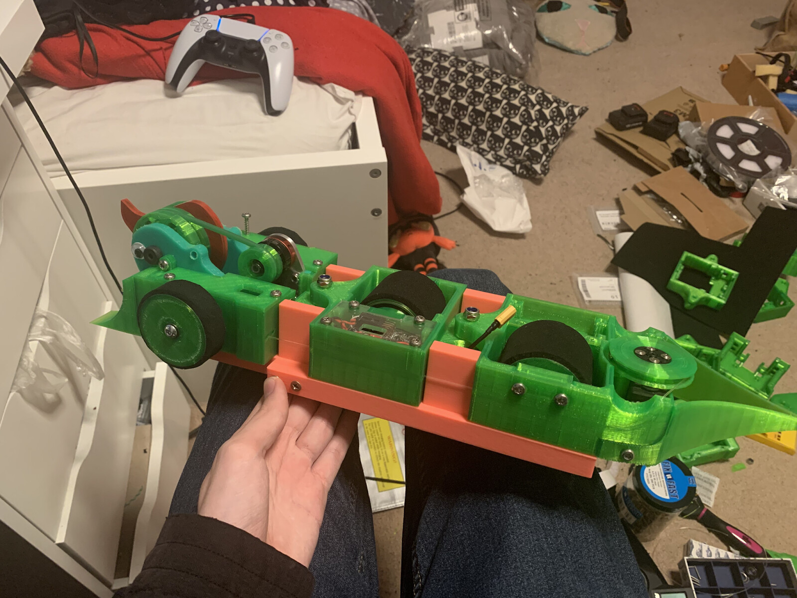
In order to both provide strength, stability and not break any motor shafts, this method uses 2 extra bearings, the larger one sits around the cover for the motor and keys into the back of the wheel, while the smaller one goes on the end of the aluminum cross shaped part, through the wheel and sits inside the chassis, this in theory means any force from the robot sitting on the ground or any hit to the wheel should be taken by the bearings and not the motor. These parts are identical between the 2 back pods and are simply rotated 180 degrees. The main part of these drive assemblies is the green tube part made from TPU, this keys into the frame and is held in by 4 m4 screws. The tyres for this design was an interesting challenge, while the general consensus is to custom mold wheels for the best grip, due to the size and weight requirements i did not think this was an option, instead opting for adhesive backed neoprene rubber foam. This allows only 3mm of tyre but the grip levels are unknown as of now.
Part 5: The bit with the tail
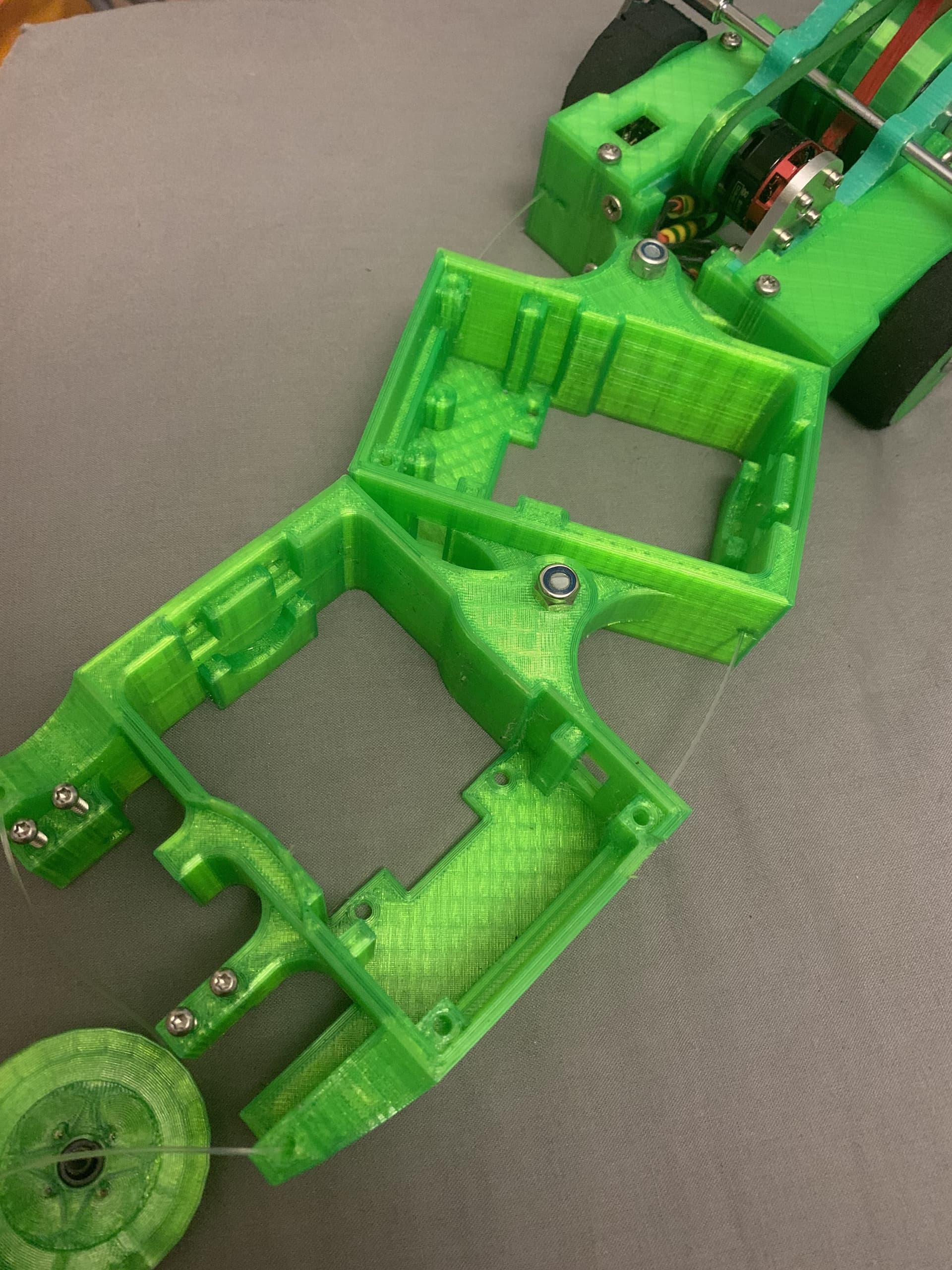
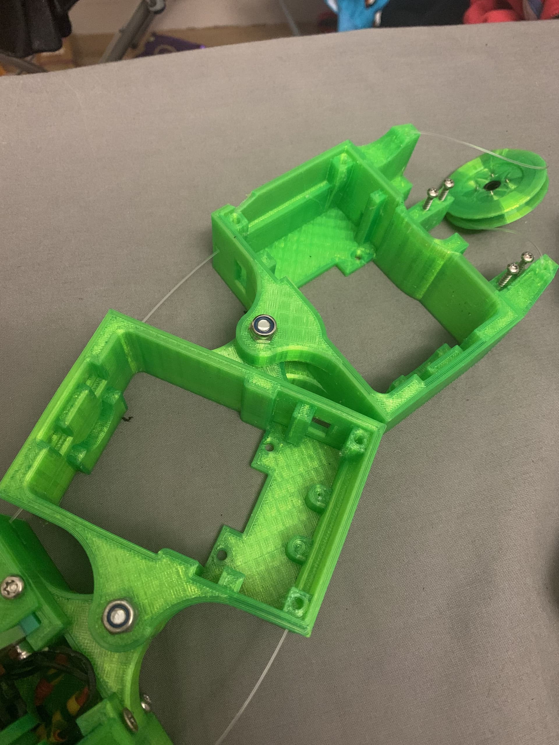
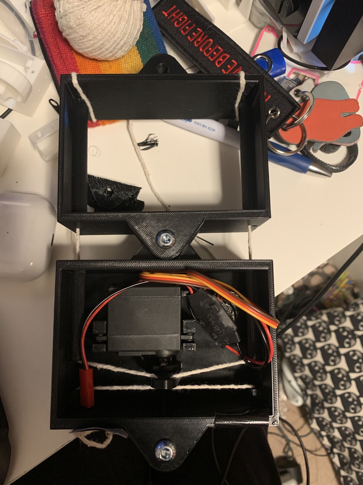
The back pod is indeed where the tail sits, but the back pod is much more important than this. This pod holds the key to the whole robot, the turning mechanism. While this is the most important and most unique part, it’s also the part I had the most trouble with. Initially the plan was to use a servo in normal form like how it was placed in the prototype above. This method would have allowed me to get the same turning range at half the rotation due to it pulling on the middle of the cord rather than the end. Unfortunately due to the reduction in pods from 5 → 3 it meant the only 2 places to put the servo for turning is the back or front, and since the front has a big spinny thing, it had to go on the back.
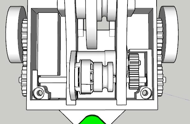
This is the final design of the rear pod, without the tail, the servo sits in a vertical mount and holds a winch. This winch was one of the big changes since the original concept, originally it was to be a single arm and would be able to use a normal servo to have positional control over the angle of the snake. Unfortunately due to a mistake in a calculation no normal servo would have the correct range i needed, and so the servo was made to run continuously. This means I have almost infinite range, at a cost of it being a massive pain to drive. The cable position proved to be an issue here as for the robot to work they run in the middle of each pod, but if they came out at this point on the back pod, it could cause them to be tangled up as the angle up to the winch would be very steep. This resulted in a channel for the cable to be redirected up and in line with the servo, and also left a gap underneath for the tail to mount (very important)
Part 6: The dangerous end
Spinners are funky, but fun. My super evil plan was to make a vert and make it funny so people are not mad i made a vert, HAHAHA. Nah just kidding. The reason it is a vert and not anything else is for a few reasons. The first is that it’s what I made it in game as, and I wanted to honor the source. The second is that being a vert would add gyro and I think it would look even more funny. Finally I knew that a control bot like this would not work as they need to be able to move well, and this does not. The only option left other than a vert is a horizontal, and while I did consider it, I decided not to do both from a logical standpoint of fitting components, and i didnt want to stress the turning mech more with force from the spinner.
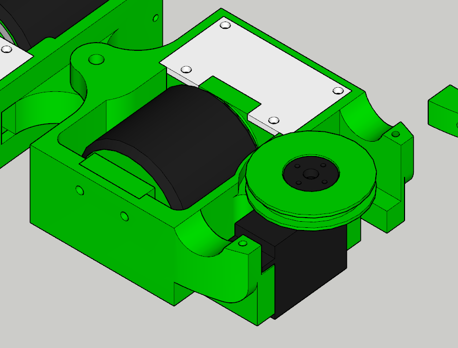
I have experience with spinners in both ants and feathers which helped me a lot when designing here but I knew that this would be a little different since the main focus is not on the spinner. I elected to run a TPU chassis with HDPE uprights machined by Sion (thank) with an alu motor mount and a green PU belt, after seeing it done by a few people in the scene. The weapon sits on an 8mm shoulder bolt with 2 608rs bearings in TPU pulley and spacer, all holding a 8mm thick hardox blade via 3 m5 bolts. Fairly standard stuff, if not slightly under specced. But this wasn’t what makes the front pod interesting. It’s the non-spinny bit. Initially I wanted to keep the “4wd” dream alive and drive both front wheels off a single 22mm using a gear train and a dead shaft. While cool, it became very complex very fast and unfortunately I had to abandon that for both weight and sanity.
While it never worked out i’m quite happy to have given the design a go, it was a fun challenge to fit everything in such a small area. The main issues with this came down to it being a fragile system and almost no room for all the electronics I needed. Moving away from this left me with a choice, keep the wheels as free spinning, or ditch them and slide along the ground instead. I elected to keep them, running on a 5mm bolt with 2 bearings per wheel and it has actually made a noticeable difference to turning the robot, especially with the weapon.
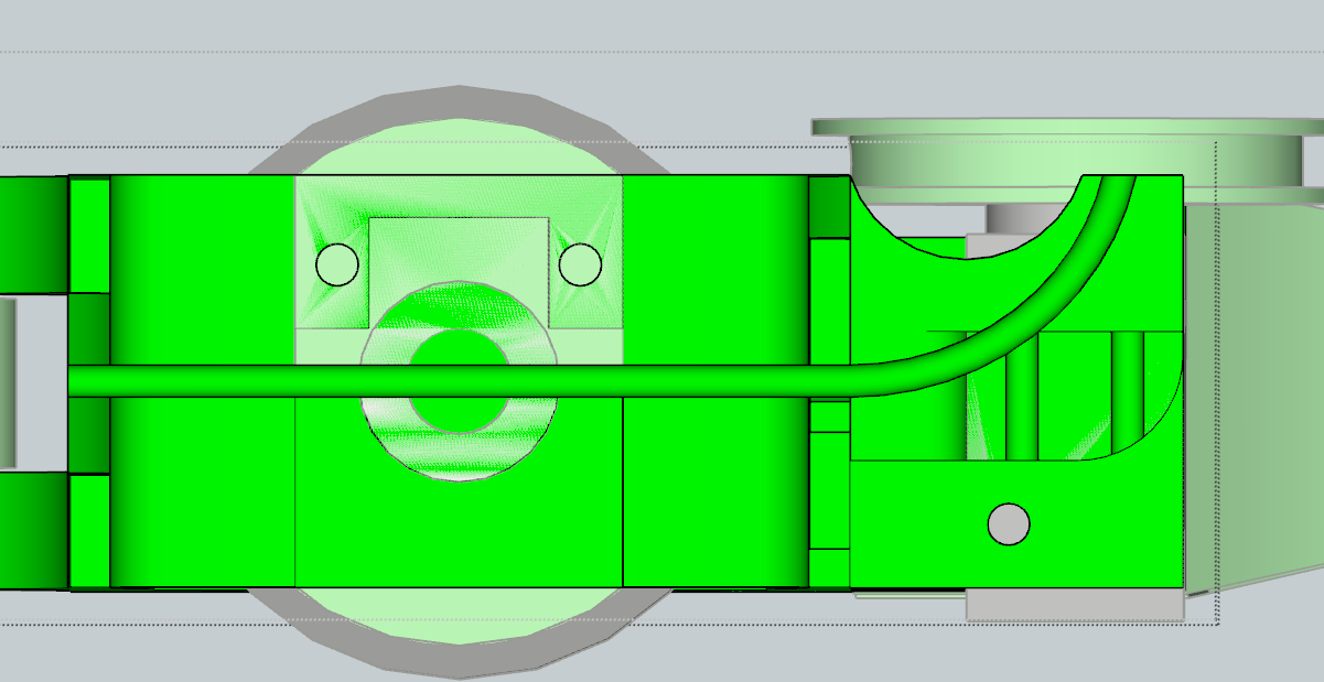
The other interesting thing about the first pod is the attachment of the cables. The cables from the rear pod feed through and attach at the front. These cables go through the back plate of the front pod and wrap around a m5 bolt that goes through the chassis and goes into a m5 lock nut. Initially the plan was to have some sort of tensioning system so that I could ensure tension without having to take the lids off, however this proved to both be too hard to print and did not work as expected in practice. The image below shows how I intended to do it.
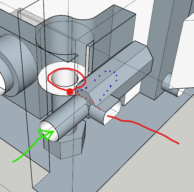
The green arrow shows a bolt screwing in, red shows the cable in normal operation, and purple shows how as the green screw goes in the cable takes a longer path and therefore increases tension. Unfortunately the issue was the cable would tend the slide under the bolt. The idea of wrapping around and tying the bolt also never made it in as the cable was too stiff, and so the current design just has the cable going down the m5 hold and being held by the thread of the bolt. This has worked well enough for now. The final top down view of the front pod is visible below.
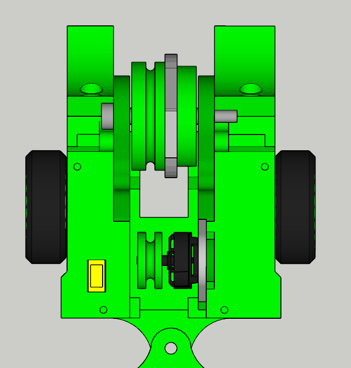
A few things to note on this final design. The ground game is just TPU. I took a peak at icebreaker and thought, looks good, saves weight and did that. The other thing to note is how the weapon bulkheads are actually offset from the center of the bot. This is due to the battery going on the right side and being bigger than the electrics on the left side. However I accounted for by making the spacer less wide, meaning the weapon is still central. Initially the weapon was going to be a 2 tooth design, but the hardox order would not have been ready and so I got a weapon from Henry Strang that he was not using, and it literally saved the whole project, and looks better. Thank you so much <3
Part 7: Does this make it an electric eel?
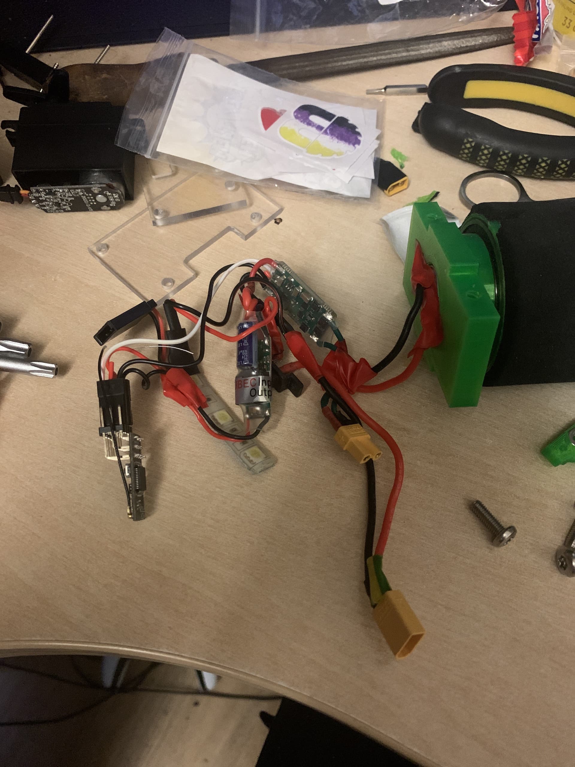
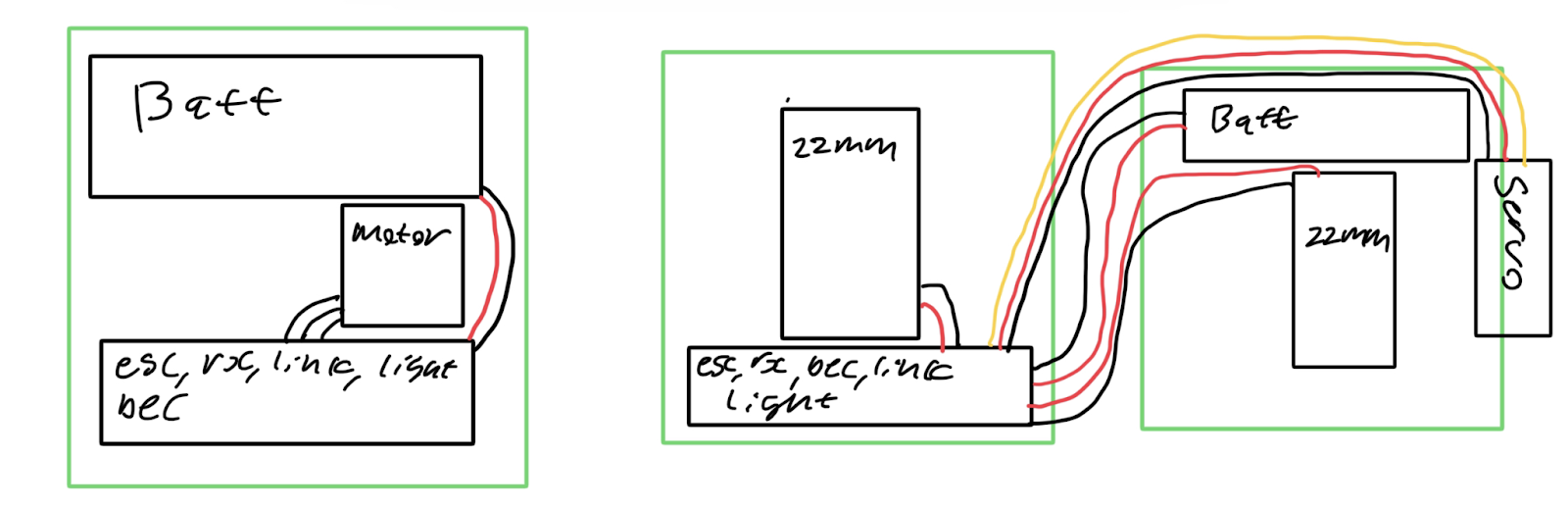
Electrics, all the robots need them, and usually it’s easy, you go to the BBB shop and get some motors and what everyone else uses. However, this is not really a normal robot (shock) and so has some funky choices for electronics. The whole robot is actually 2 robots, one for the front and only for the spinner. The back “robot” houses the drive and turning. This means there are 2 batteries, 2 receivers and 2 links. The front of the robot houses a 380mah 4s LiHV on the right side, and a 4ch BBB rx, emax bullet 30A, 3a BEC, power light and link on the left. In the middle sits an emax 2205 2300kv for the weapon.
The back is where stuff gets funky. Despite having 2 22mm motors, it only needs 1 BBB single ESC as they both only need to go forward and back. The middle pod houses this esc, 1 BBB 22mm, 4ch BBB rx, power light, link and 3a BEC for the Rx and Servo. The back pod houses another 380mah 4s LiHV, the other 22mm and the servo. A total of 7 wires run between the 2 back pods, 2 for power, 2 for the rear motor, 2 for servo power, and a final servo signal wire. I have drawn the following diagram to illustrate what I mean.
Part 8: What do you even make a snake from???
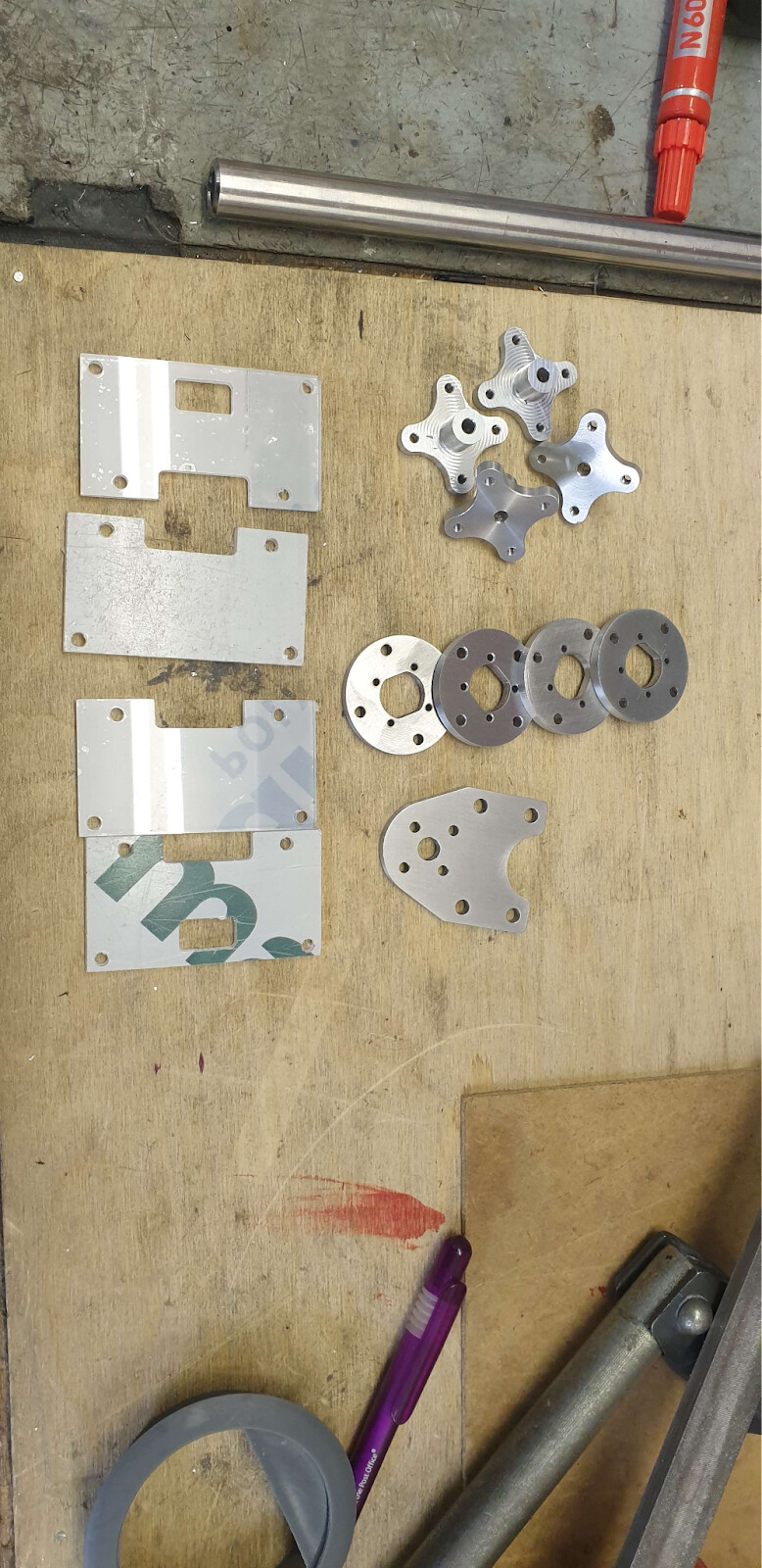
Answer, a lot and lot of TPU, i ended up going through 2 kg of green esun TPU. This was enough to make at least 1 spare of every single part in the robot. Initially the prototype used pink PLA+ for testing and was going to be used as a spare, but it’s so brittle that I ended up just printing more TPU parts. The other parts that are not TPU are either aluminum machined by nat, teamsc, or HDPE as mentioned in part 6, or polycarb for the rear lids… There are 3 unique aluminum parts in this build. The weapon motor mount, drive motor mounts and the custom wheel hubs. These were all made amazingly by nat and would not have been possible without him.
Part 9: How does one contain a snake?
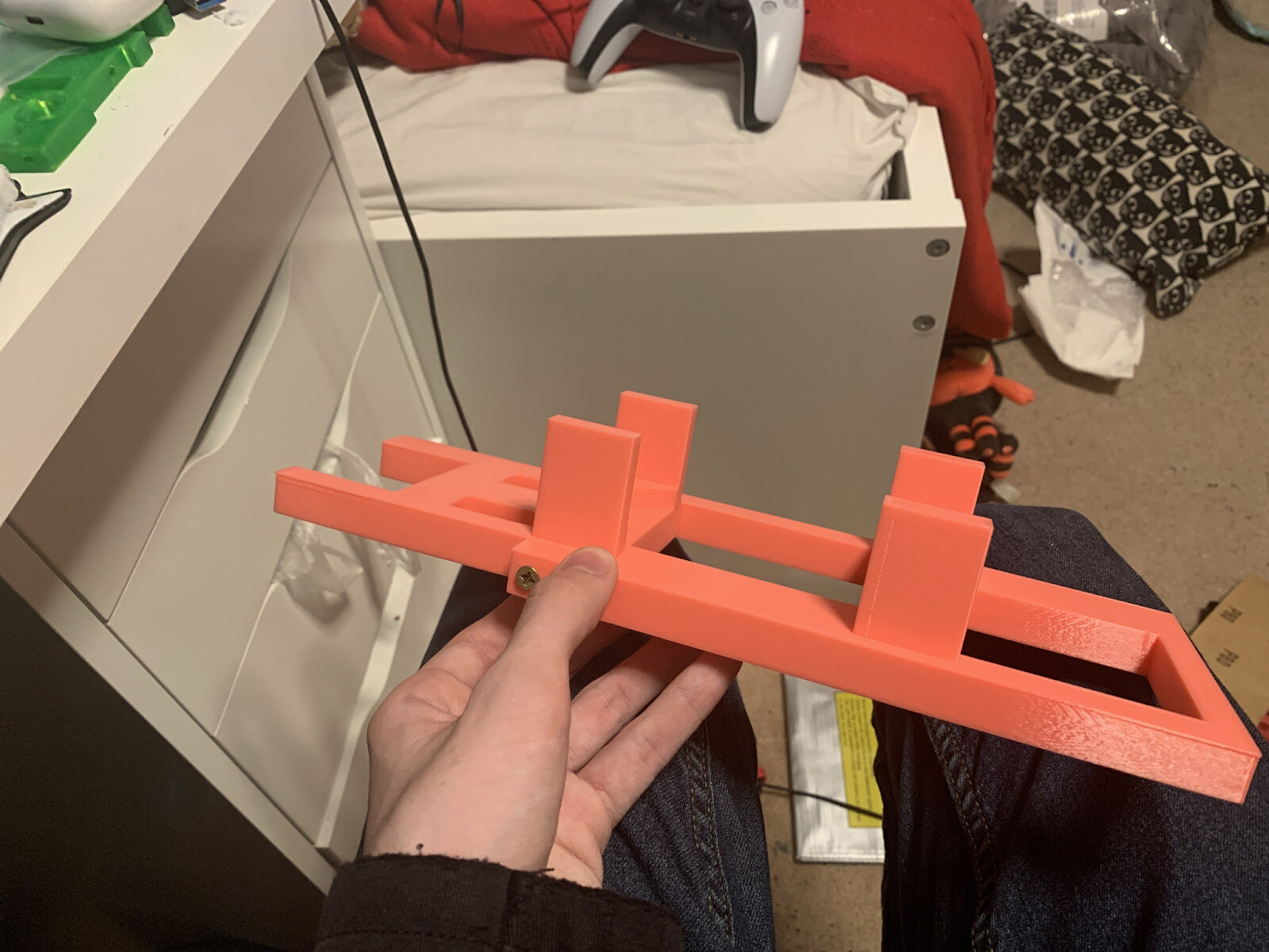
The cradle was an interesting challenge for this bot. Since it’s not a very normal robot, a box would not suffice as the wheels sit in the center and it would just drive off. Another thing to consider is the turning. The cradle is supposed to stop any movement from happening in the event the robot turns on. And this would include turning. The design I came up with has posts that go between pods and hold it in a line, while also keeping all wheels off the floor. It was made in 2 parts just so it could fit on my printer. And of course, because its me, its pink.
Part 10: A 4 wheeled vert
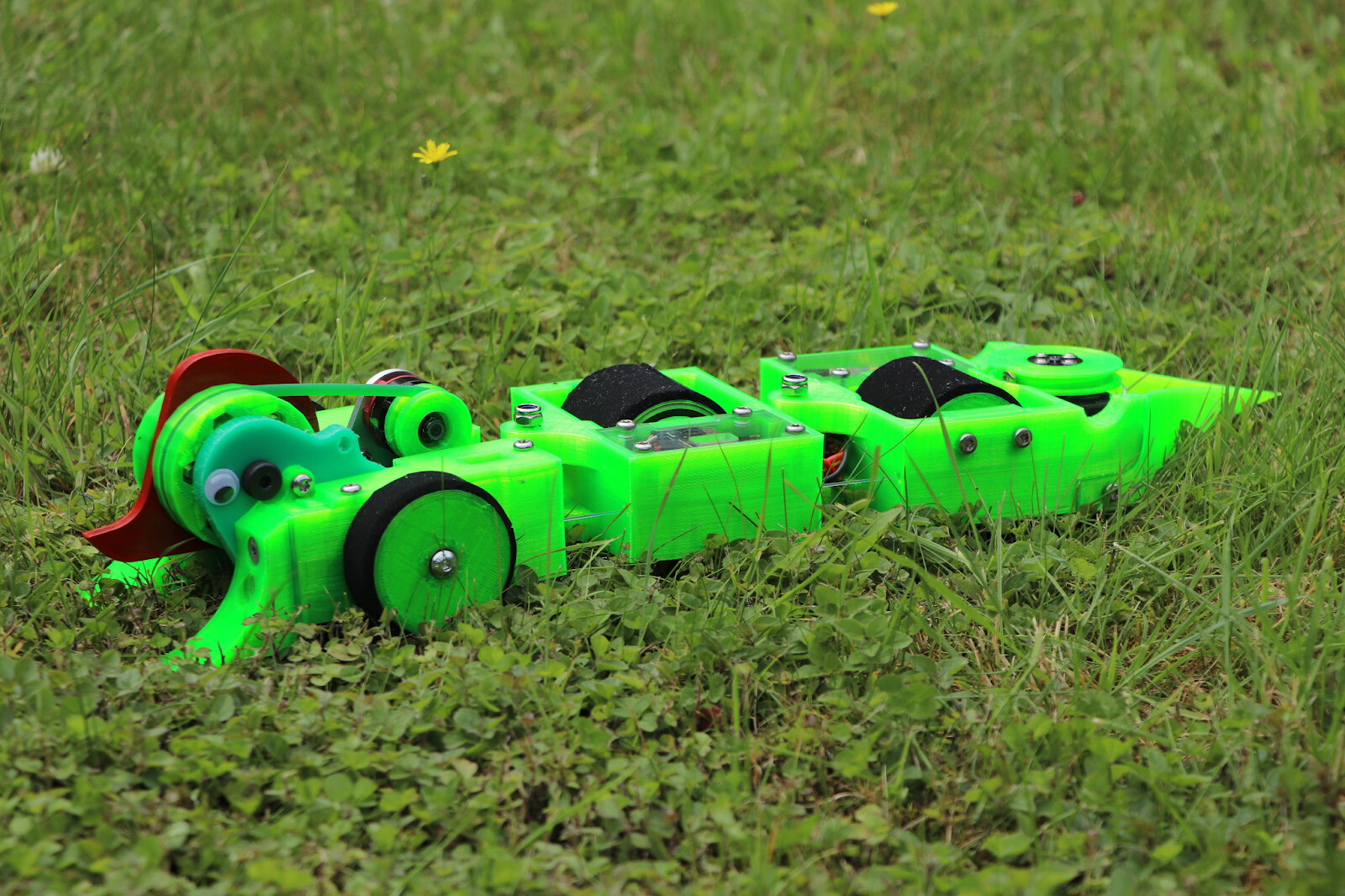
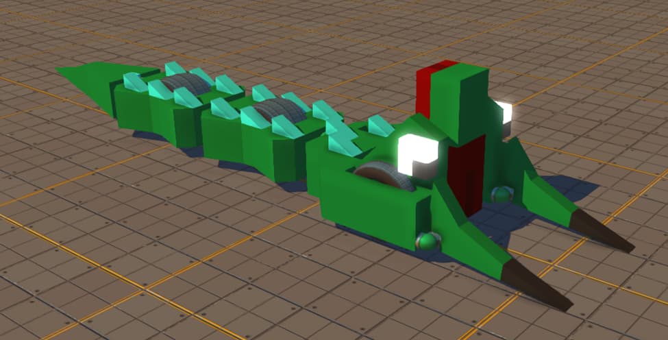
And so we end this journey through the build of one bendy boi. Thank you for taking the time to read this, this is by far the most fun i have had making a robot and i hope i can bring some of that fun to everyone else when it fights. It was a pain to keep it a secret for the roughly 6 months i was making it, but it was so fun when people saw it for the first time. Thank you to everyone who has helped me along the way, but especially to Siôn Williamson for keeping the idea alive when i didn’t believe, for helping with a few things and for keeping me on the crazy idea train.
I will now leave you with a last photo of the snake in its natural habitat.