Ok so I know I still have more of my jackhammer write up to finish but I thought I’d make a start on this one so it can operate a bit more as a build blog as I work on it. Here goes…
This is my new beetle under the working name of Rotavator which I’m trying to make in time for the BBB new blood event in may. It may look like a pretty standard vert but I can assure you it is not. Lets start with the obvious stuff then. The drum weighs more than 800 grams and has a battery in it.
My initial concept was inspired by noob tube. I thought what if instead of having silly wheels on the ends you could just hold the spinning tube of death with a separate robot and maneuver it around like that. This would make it far more controllable whilst still keeping an insane amount of weight in the weapon. I thought this idea was pretty goofy and I hadn’t seen it done before so here I am making it.
PSA: I am absolutely aware that this will not be at all competitive but I’m trying to see it as more of a design challenge so I’m less sad when it’s awful.
Lets start with the weapon then, because I designed this before I even started thinking about what the rest of the robot would look like. Pretty early on I decided that it was going to be a hubmotor. Besides the fact that I’m going through a bit of a hubmotor phase at the moment I still reckon this is the only decently compact way of doing this design in the current form. That being said I still considered loads of other options including planetary gears and at one point I was also contemplating having a counter gyro spinning inside the drum itself. This is still something I might consider later (realistically it’s really not) but for now lets keep it simple (even though this is anything but).
I settled pretty early on having the hubmotor (which I still needed to design) on one end of the drum and then having the other end supported by some kind of bearing and shaft combo. I also gave myself my usual constraints of doing it on the tightest budget I could (given the whole student vibe), and doing as much in-house as possible. This limited me to my standard hdpe and 3dp along with 2D metal parts (no expensive china beaters) and for any cylinder-ish parts to be constrained by the size of my tiny hobby lathe (and my poor ability as a machinist). Discarding the repeat compacts I’d bought for Jackhammer and some of the electronics I had lying around I wanted to make this bot for under £100 (ambitious I know) including any spares I may need.
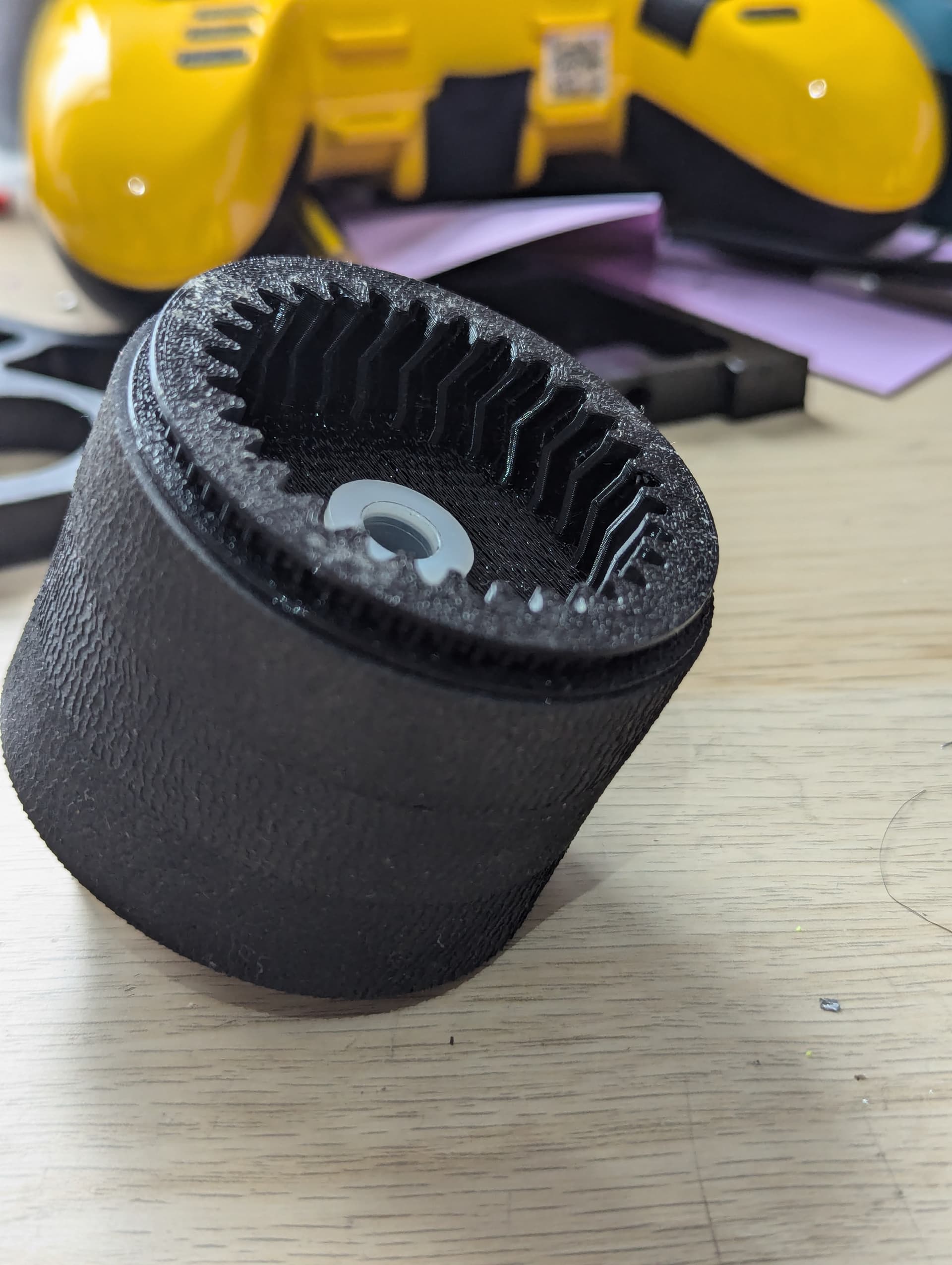
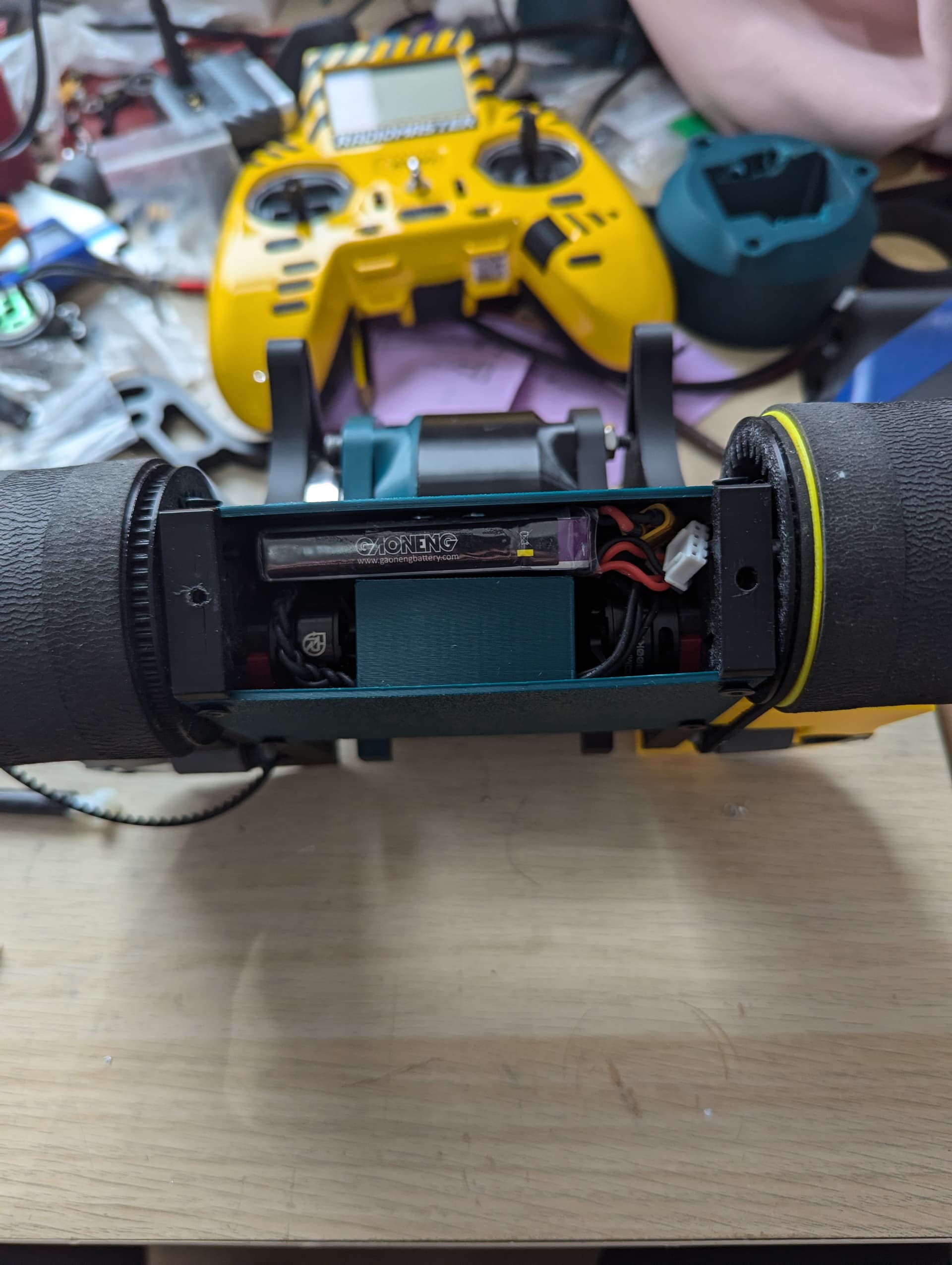
I experimented with loads of different designs for the drum, at first mainly pursuing a 2D beater inspired by the one on bulbaroar with the electronics housed in the centre. After that I moved onto one with discs which slid onto the 2d beater before settling on this current design. One disc houses the hubmotor and the other one is free spinning and turned by these 6mm shoulder bolts which pass through the whole drum. It sits on a 10mm shaft and a bearing. This leaves the centre void nice and free for my battery. The idea is that the outside shoulder bolts along with a bunch of tpu should protect the battery from anything too nasty.
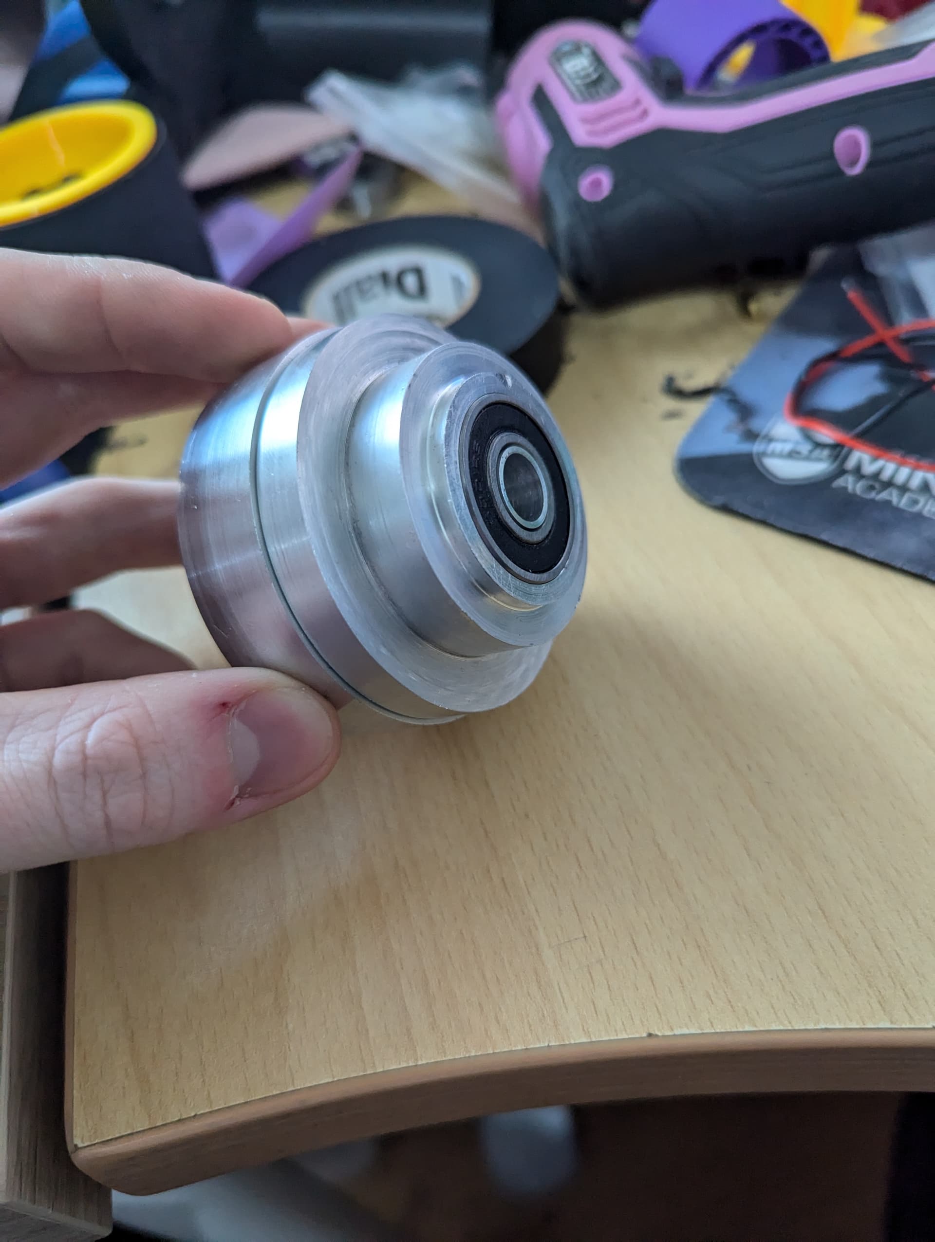
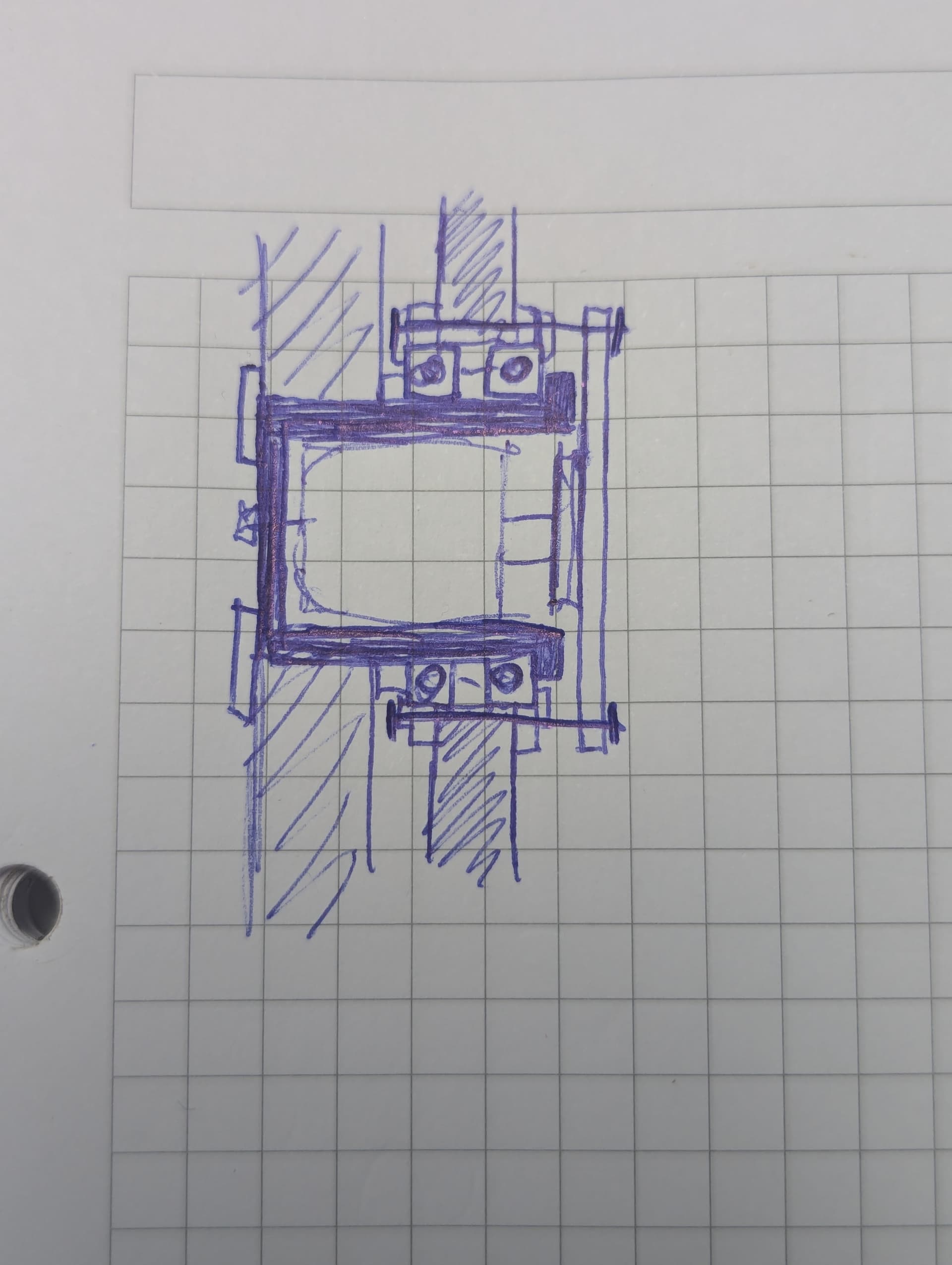
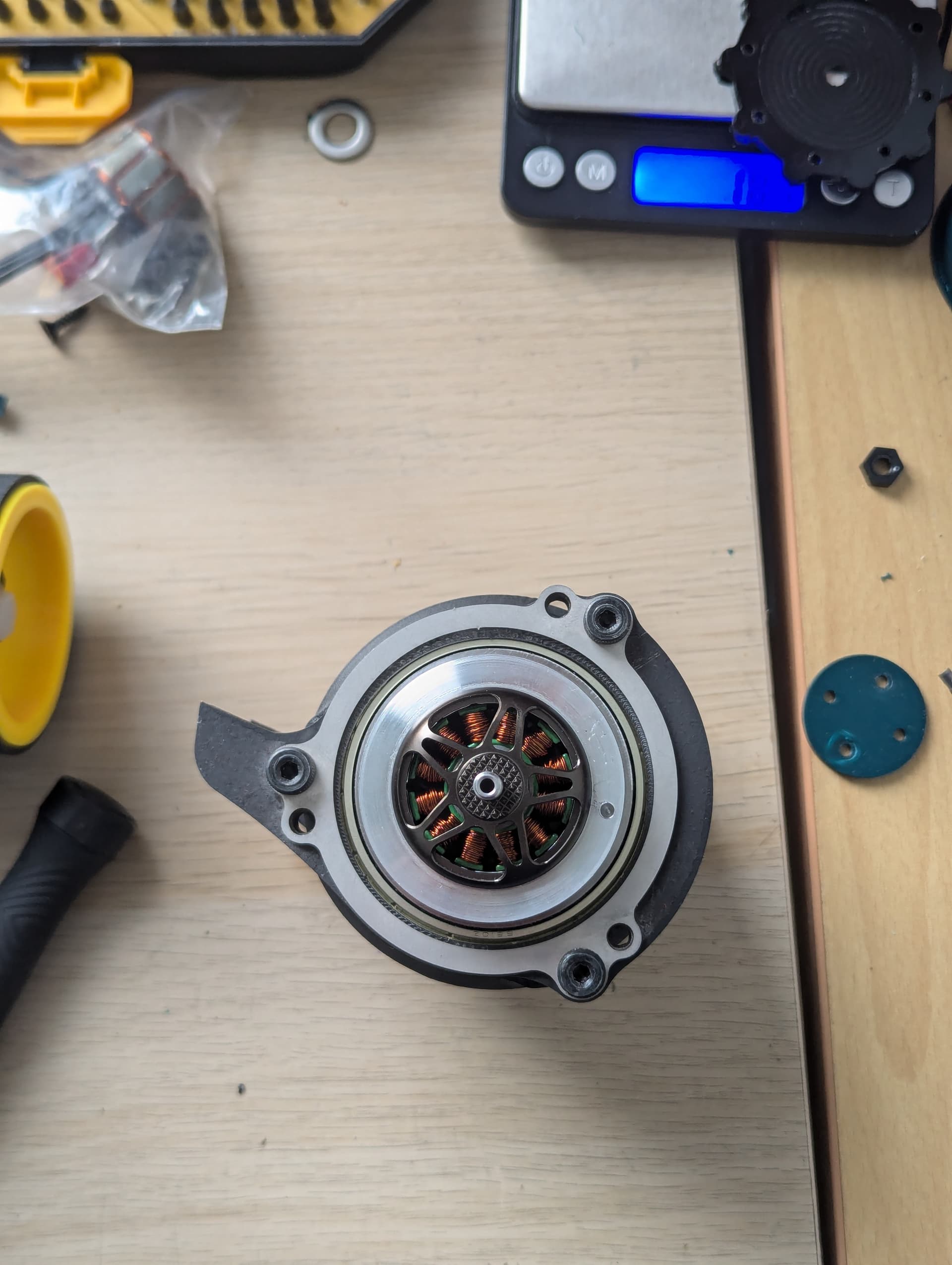
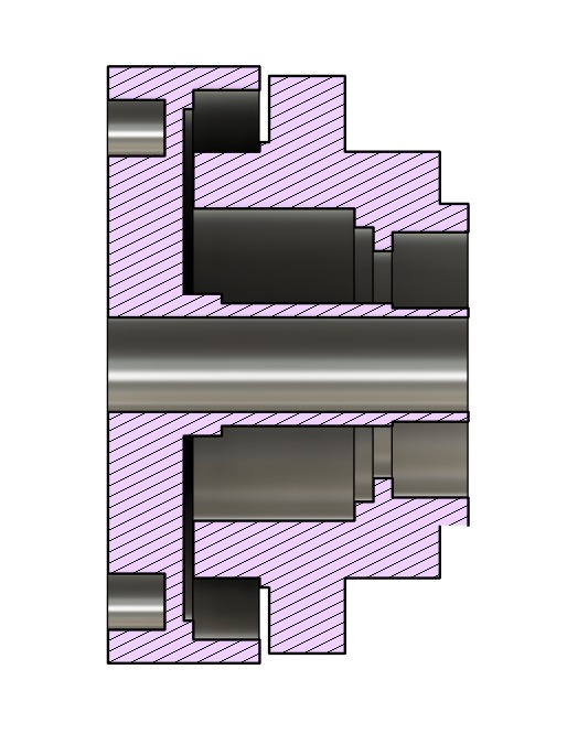
So the hub. The hub was kinda tricky because on a brushless outrunner the magnet ring bit is on the outside and the electriccy wirey bit is on the inside. This is annoying because I want the electriccy wirey bit to be on the outside because that’s where the disc is (and the disc is moving with the battery) and the magnet bit to be on the inside because that’s where the shaft is (connected to the chassis for the rest of the robot). The obvious answer to this dilemma would be to use an inrunner motor but honestly I completely forgot they existed because I got so invested in designing myself out of this hole. Anyway this is what we ended up with as the design for the hub. We got this lovely 10mm shoulder bolt running through the centre and classic 2 part design but I’ve turned it kinda inside out on one end with a bearing on the outside instead of the inside. This means that the magnet ring side can sit in the robots framerail and the disc can sit directly over the top/around the big bearing which should make the load transfer better and not wonk the whole thing up in impacts. Words words whatever. Heres a picture.
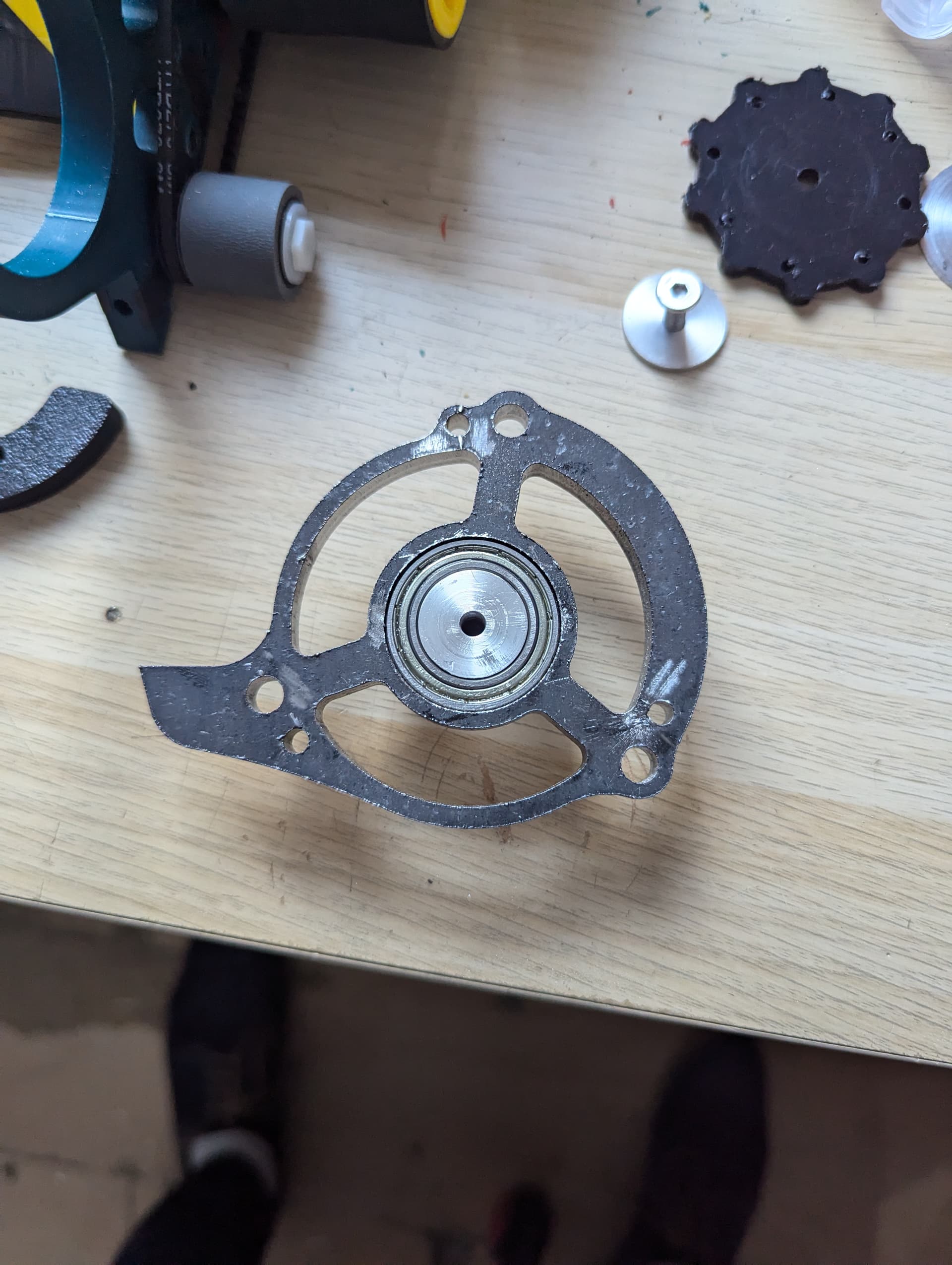
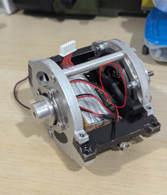
The other problem I came across was that I couldn’t add any keying features into the hub since I was making it all on my hobby lathe not on a cnc. My solution was to attach an aluminium “transfer plate” to the back of the hub which would transfer rotation whilst the shock forces would still go through the bearing. Knowing this sport’s deep hatred for bolts in shear I aimed to use steel dowel pins to couple the motor and the transfer plate with a few m4 bolts with loose tolerances to stop the plate from popping off axially. I don’t love this solution but I really can’t think of anything better without getting the hub machined properly.
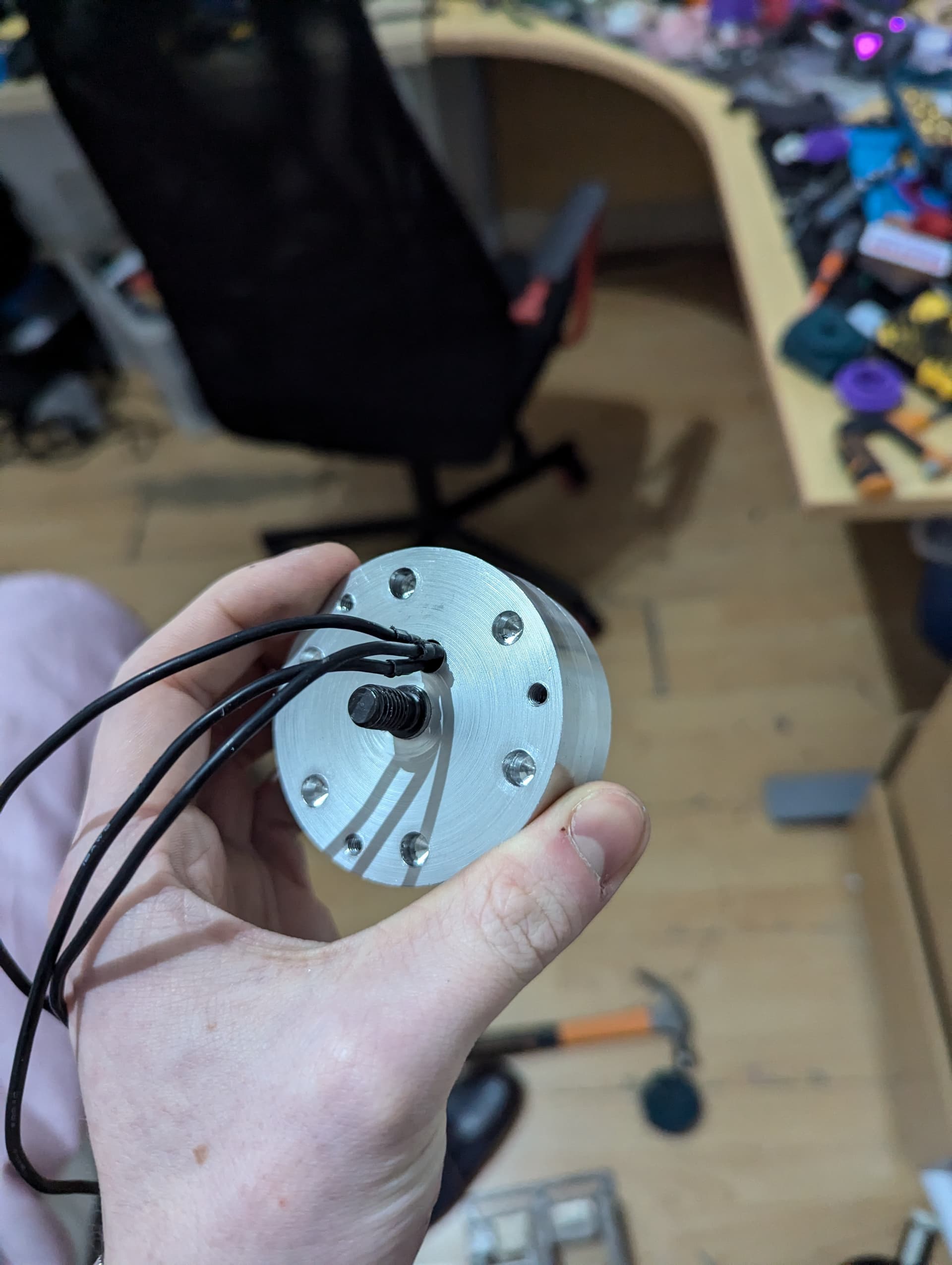
3Dp drill guide with tool steel drill bushings shown in background of second picture
I think now actually the limiting factor of the whole thing may be the donor motor I chose to design the whole thing around. It’s a 900kv 2812 which I now think may be too small for the huge drum. After seeing detonator using a pretty small motor on his MASSIVE drum I thought this would be ok, only thing is, he has a fat belt reduction and I don’t. Realistically though let’s be honest I was drawn in by the £8 Aliexpress price tag wasn’t I.
That’s pretty much all there is to say about the weapon for now other than the fact I’m currently procrastinating designing the tpu housing because it feels like a faff.
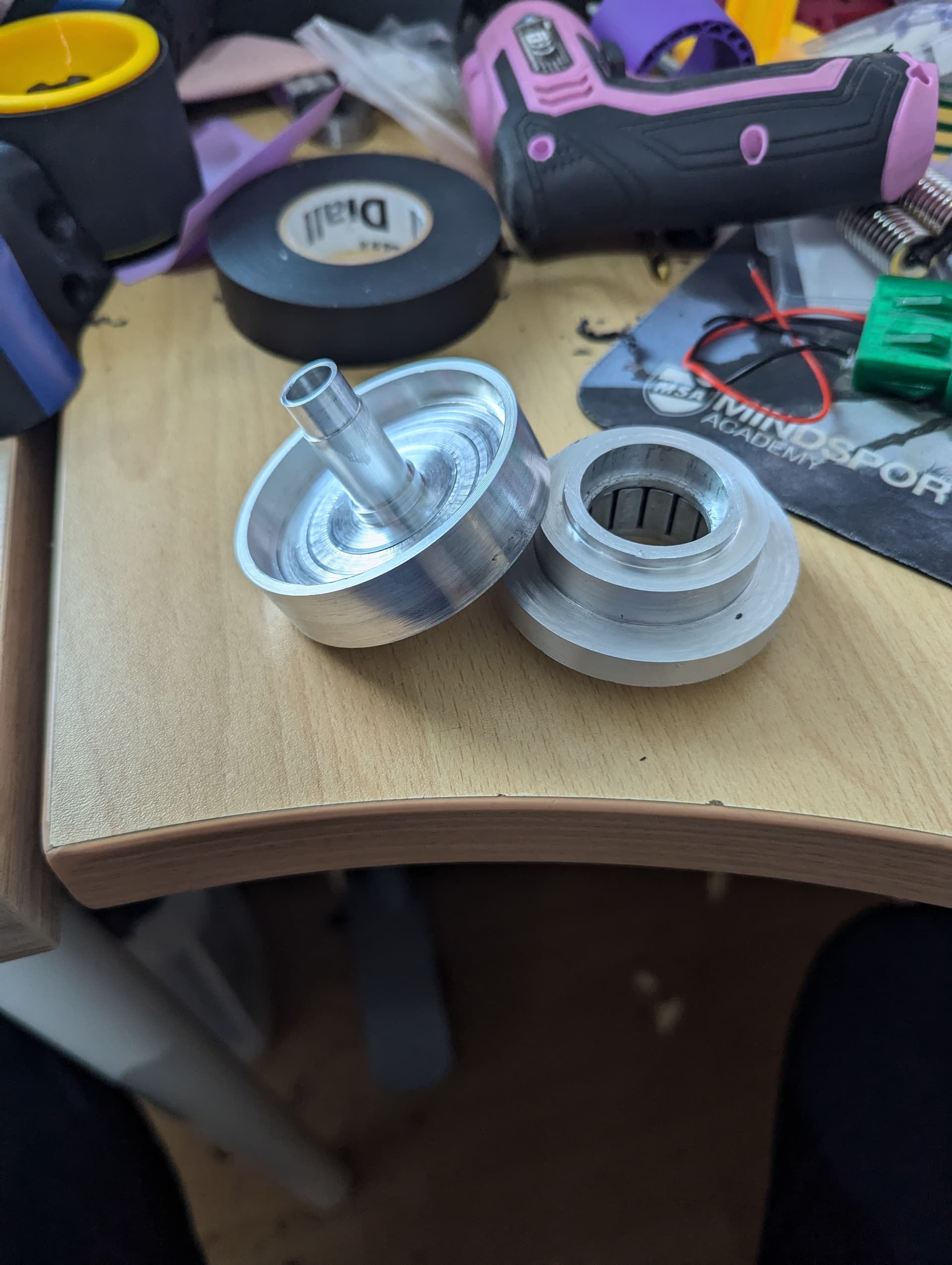
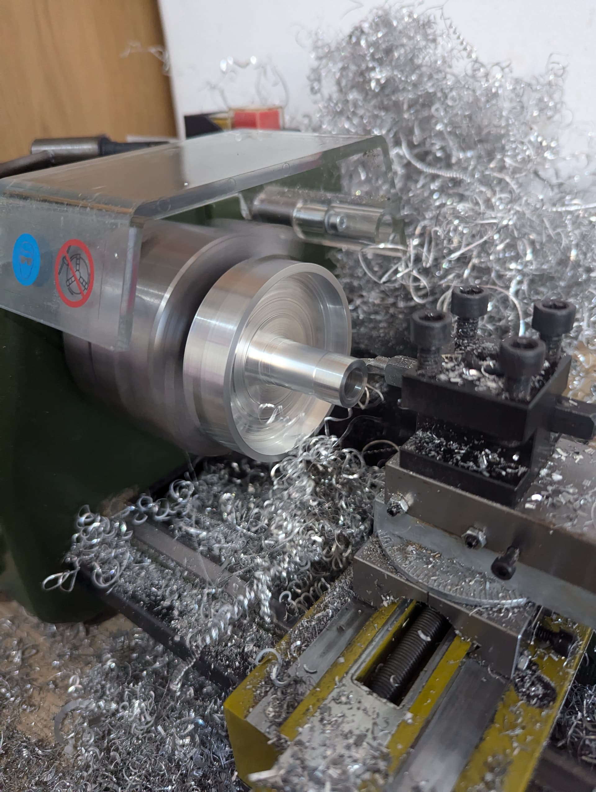
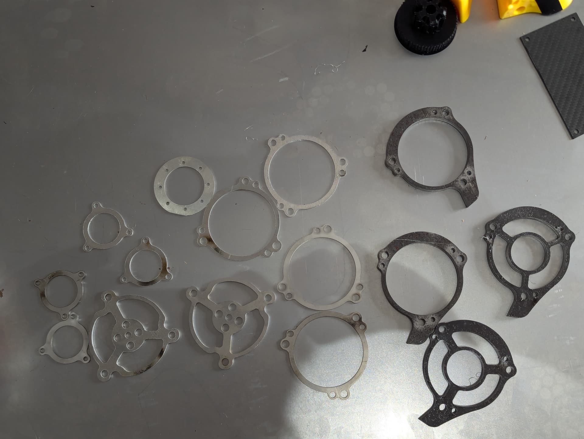
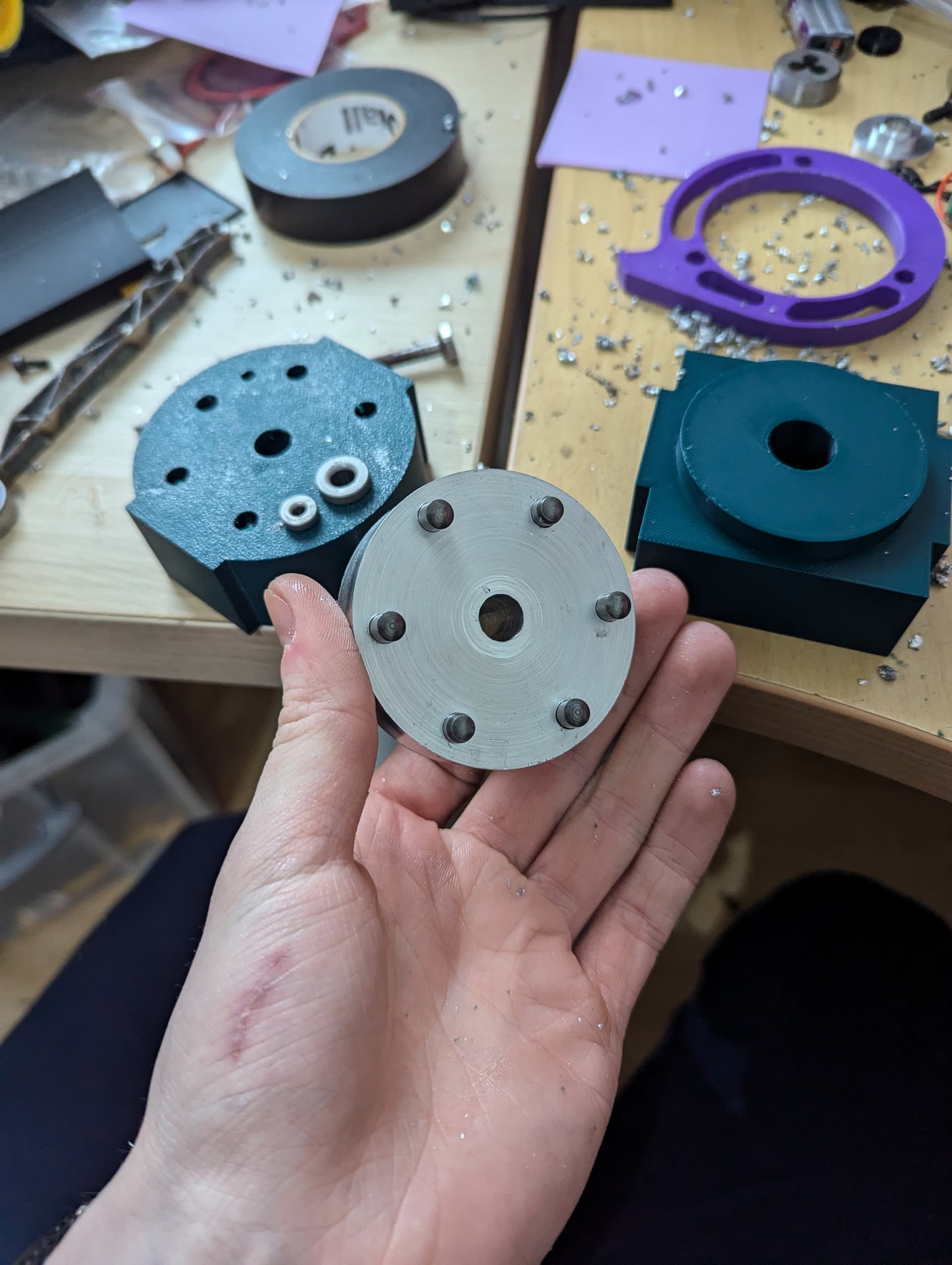
Here’s some nice pics of the hub components – note all the chatter in the part on the left – yum.
Turns out when your lathe is this size, it’s pretty hard to cut that mushroom bell profile thing. I had to position the tool on the other side of the workpiece and spin the lathe backwards in order to get the tools in the right place on the part.
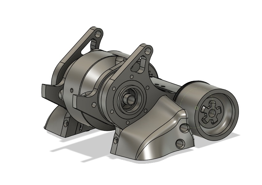
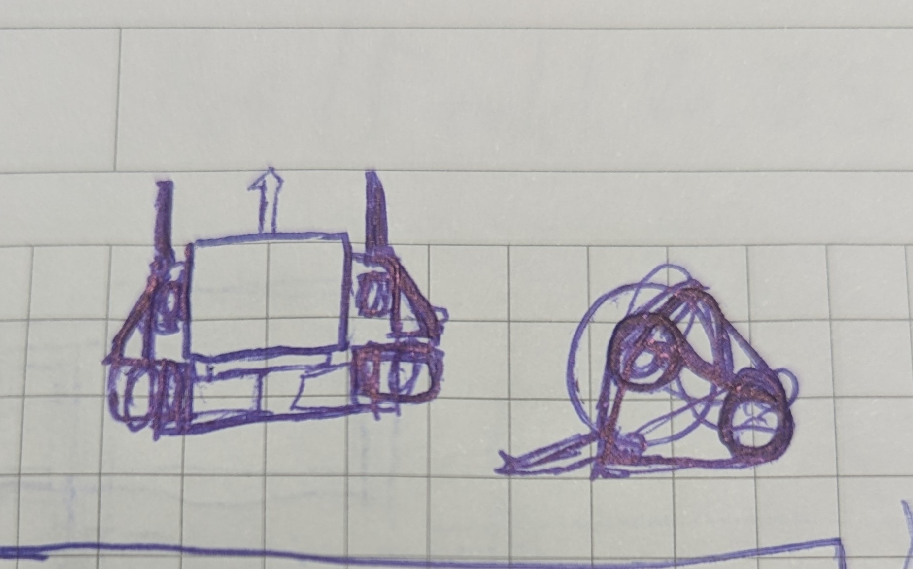
Ok so time to start thinking about the actual robot! Since my predictions are that this drum is gonna weigh a metric butt ton I knew the rest of the robot was going to need to be pretty compact. Since I was pretty happy and excited with what I’d come up with for the drum I wanted to make a cool and somewhat visually interesting robot to go with it to try and do it justice. I spent a hot minute sketching some extremely generic 4wd boxy verts before I came up with this. I loved the simplicity and I loved the tractor wheels. I made a quick cad sketch of it and was sold. This was to be my new awesome robot.
features:
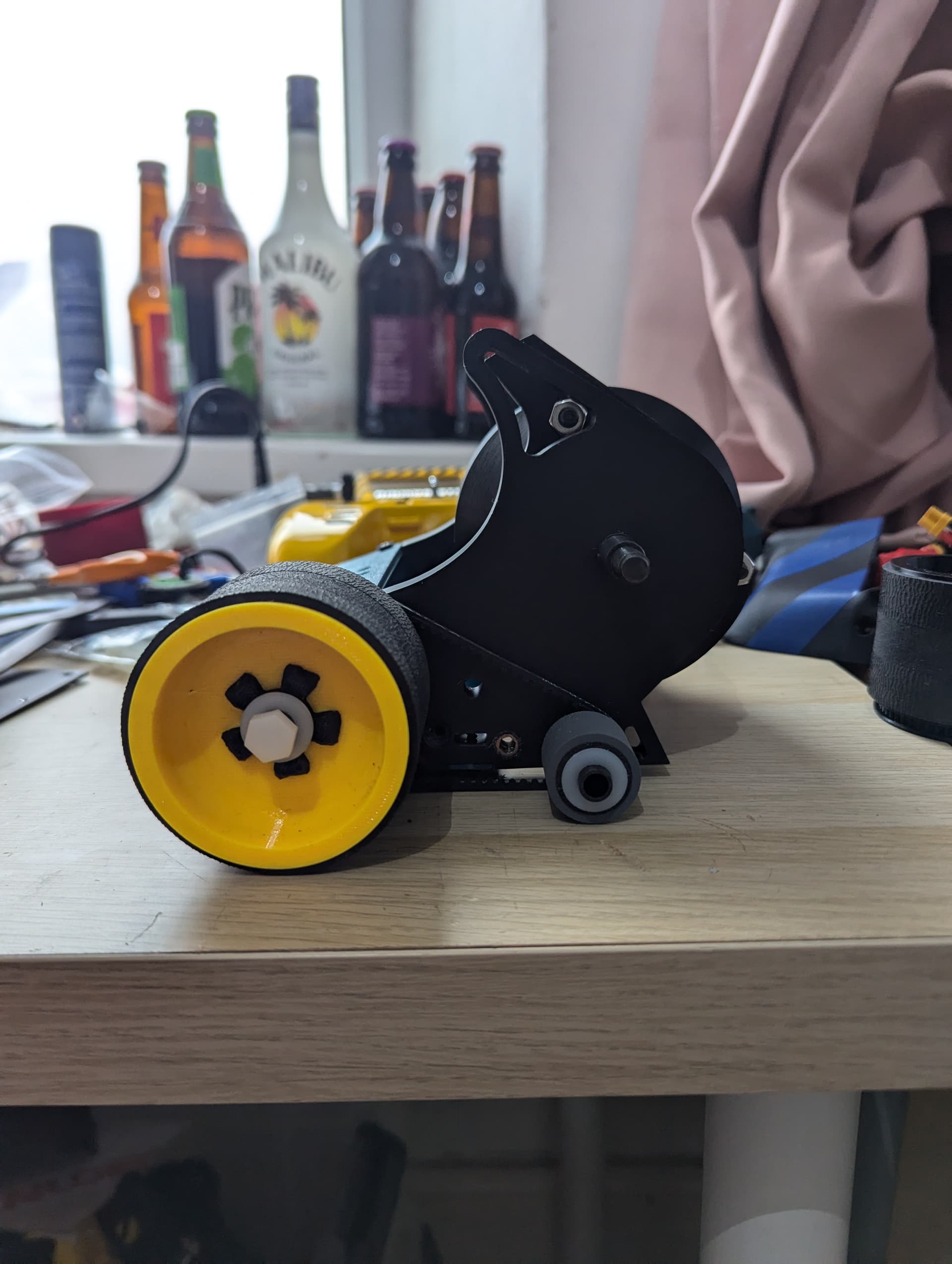
Tractor wheels – 65mm rear and 20mm front for that big disparity lol
Only 2 frame rails!!! (and they’re pretty small)
Chunky front side pod bits
Carbon fibre top and bottom for RIGIDITY
Tpu bum
2 completely separate control systems – drive and drum
Ignore the shelf of student things behind….
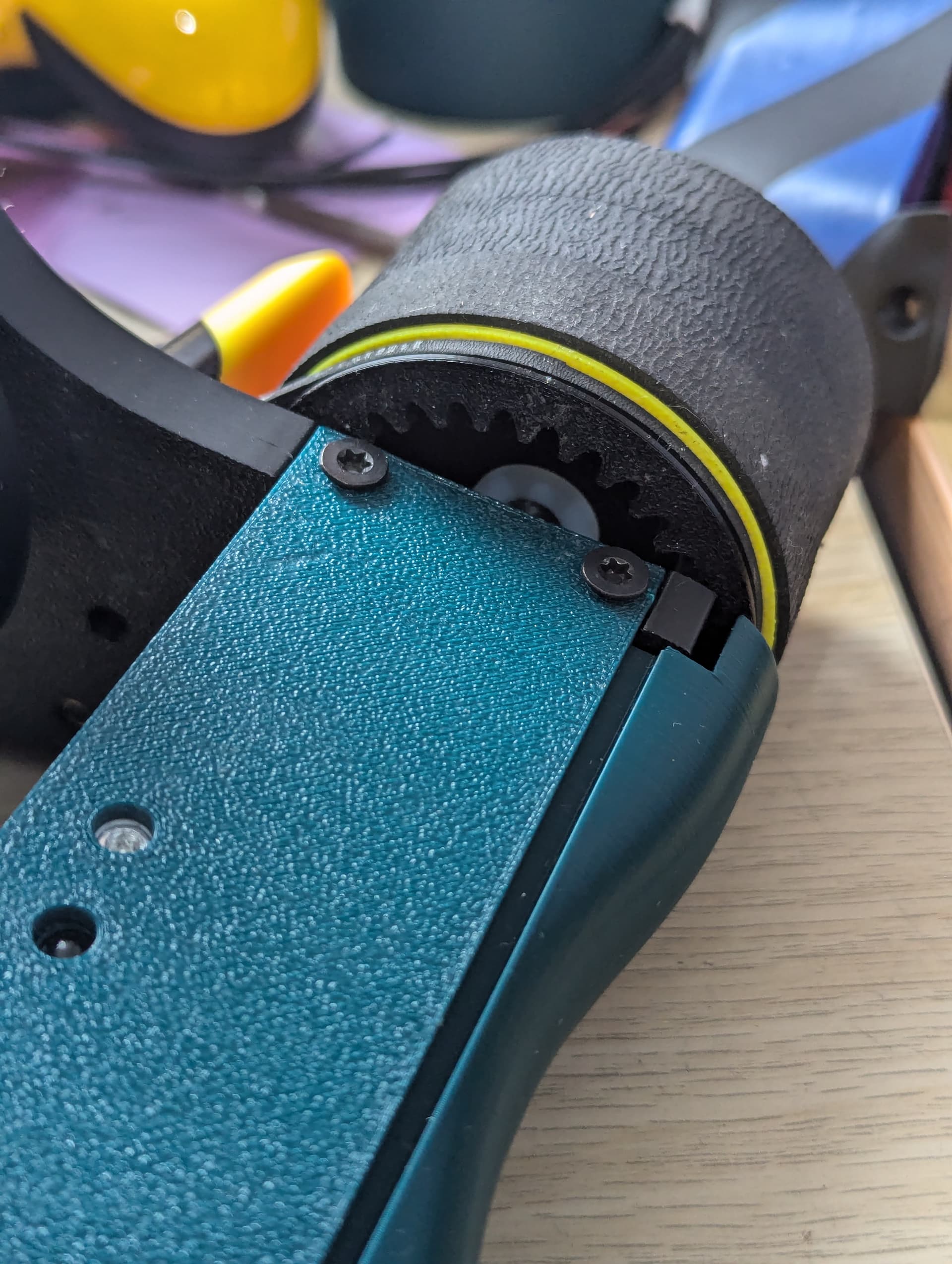
The most interesting part of this design to me is the drive system so I’m gonna start here. I loved how goofy these big wheels looked and so they were absolutely in. Due to my terrible history with 2wd stuff I really wanted 4 wheels and I love tractor style robots so enter tiny front roller wheels. These use some reject printer tyres I had left over from an antweight project last year and I’m pretty happy with them. The cool stuff all happens in the big wheel though. I wanted to gear drive these wheels because I had the repeat compacts, so putting a wheel the size of these big bois straight on the 4mm shaft would have been pretty structurally awful and probably simultaneously generated a land speed record given the speed the motors output. They needed to be gear driven but coming up with a solution that kept the robot compact was hard. That was until I remembered something cool I’d seen stratus do and use ring gears on the wheel to get the motor closer to the shaft. I played around with a bunch of variations and came up with this. I’m really happy with it.
The brilliant thing about having the gears on the inside of the wheel is that it doesn’t take up any more space width ways so the gears can be thick and fully protected without reducing the amount of tyre I can have on. It also means that I can have the belt on the outside nice and close to the frame, effectively occupying the same space in regards to the width of the robot to drive the other wheels. Finally, with the motor in this configuration, some of the weight of the robot should press down on the gears reducing the liklehood of them skipping. All in all I’m super happy with this setup as it’s sooooo space efficient. The only thing I don’t like is the possibility of debris ending up caught inside the wheel.
I know I should cast tyres but I really really can’t be bothered at the moment since these printer ones are so grippy and light. – I know that a shot from a spinner will likely cut the rubber and eject the tread but for now I think loads of superglue should be good enough.
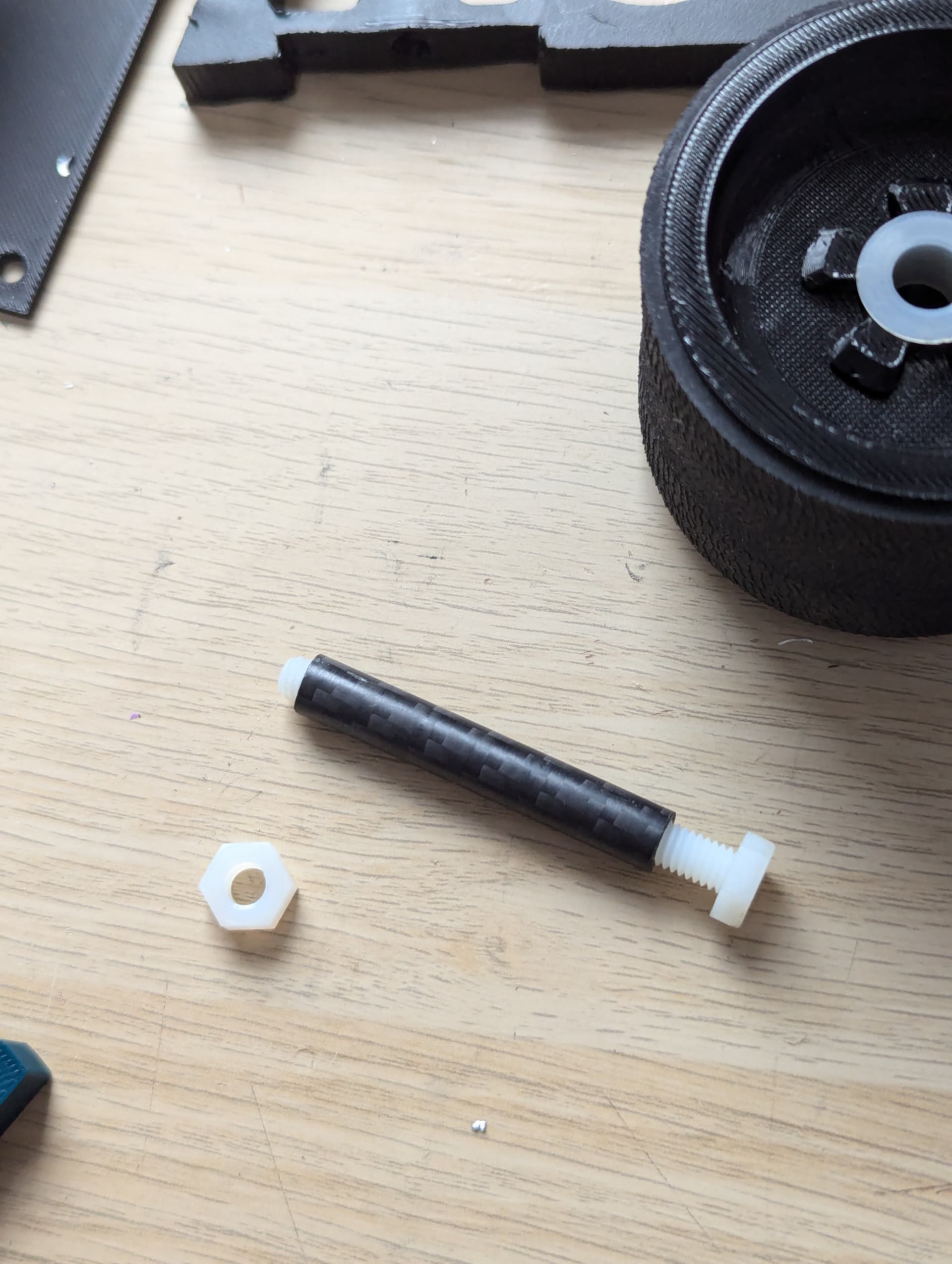
The drive axels are somewhat experimental. I really don’t think I have the weight for shoulder bolts so I’ve gone for a carbon fibre tube for the wheel to run on. This is the same one I use for jackhammer’s shoulder joint and it’s held up pretty well there. The wheels are held on axially by a nylon bolt which runs through the centre of the carbon tube. I think this will likely not hold up to hits from horizontals ripping the wheels off but I’m hoping they should be strong enough to hold up against verts with the force going radially. The wheels are designed to be really squishy so hopefully they absorb lots of the shock. Each axel weighs like 3 grams so I’m saving the best part of 50 grams with this over all 4 wheels - definitely worth it in my books.
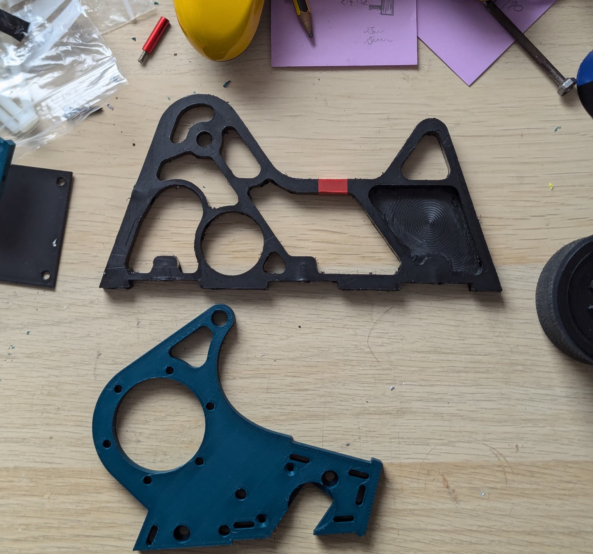
New robot frame Vs Jackhammer Frame
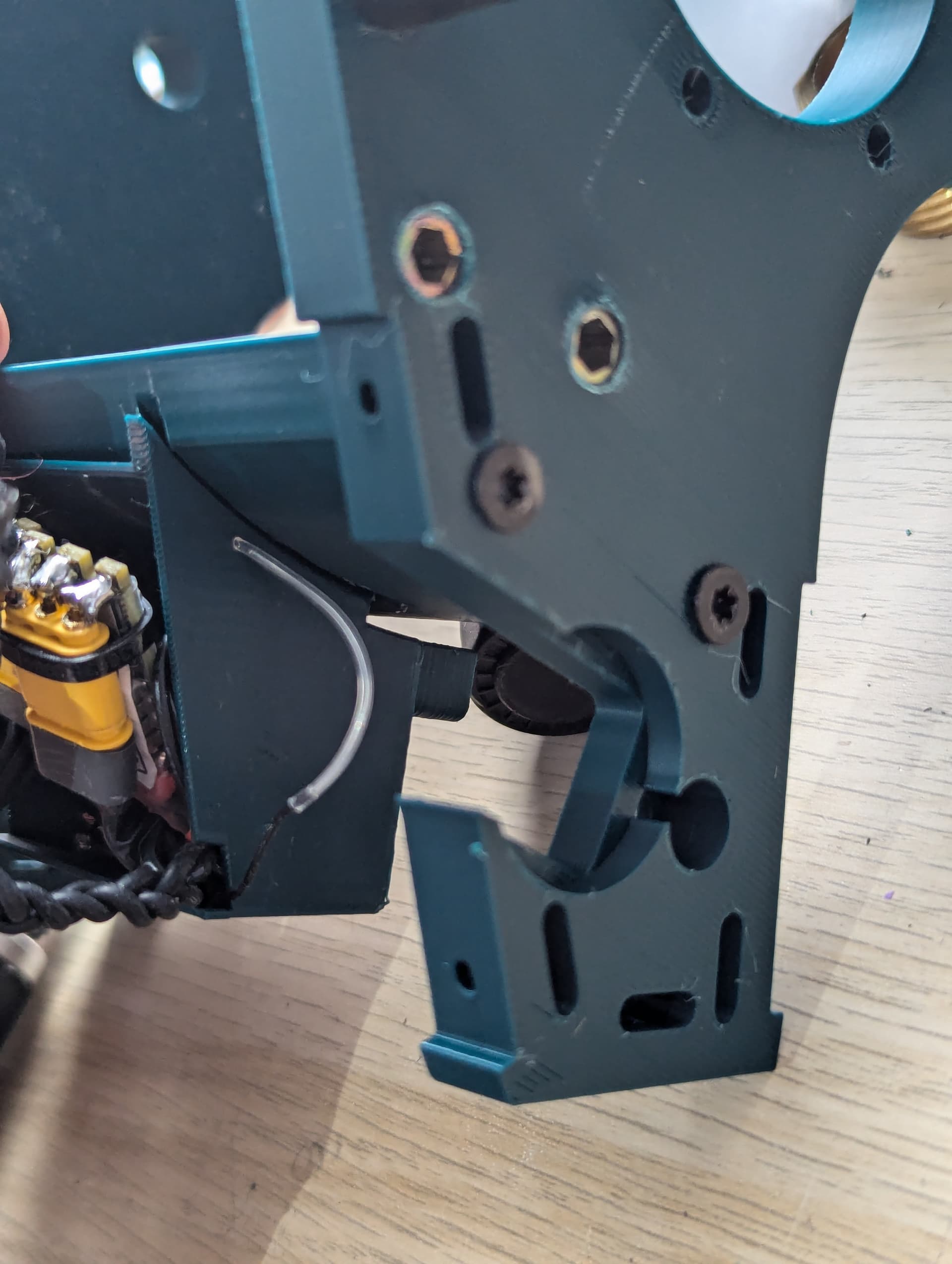
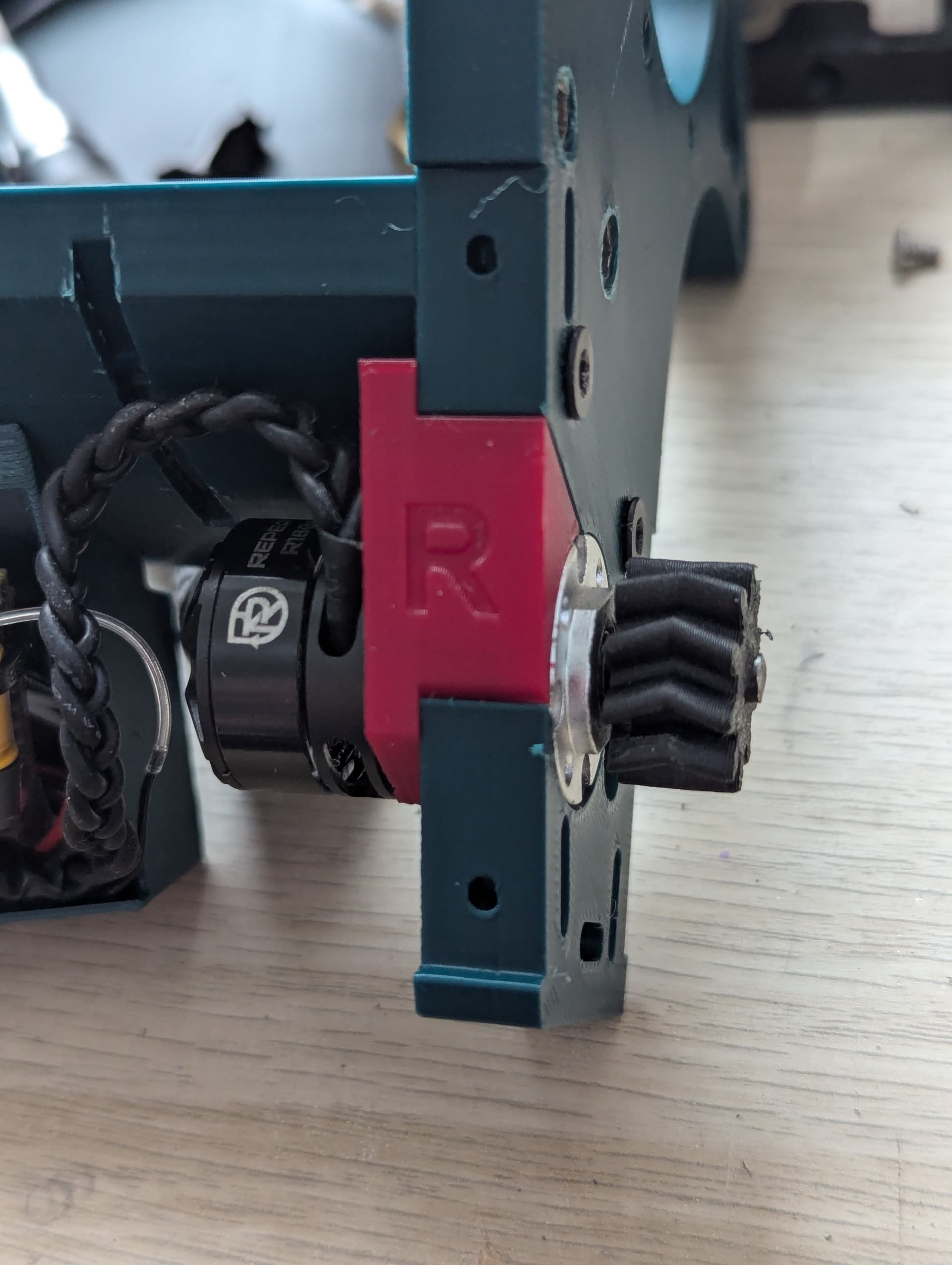
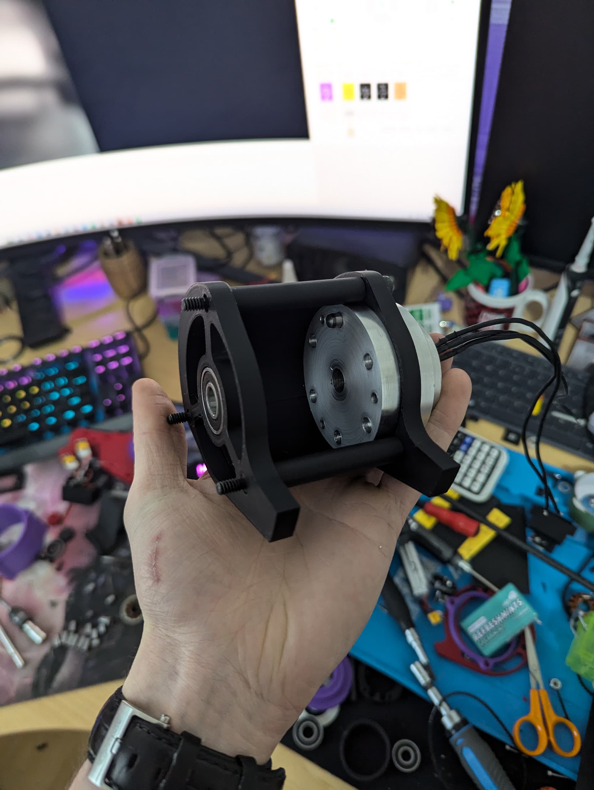
The drive motors slot up into the frame rails then lock sideways into place, held in by a little retaining wedge – again I’m really happy with this setup, as once the bottom plate is off, I don’t have to remove a single screw to get them out. A far cry from Jackhammer’s complete lack of serviceability.
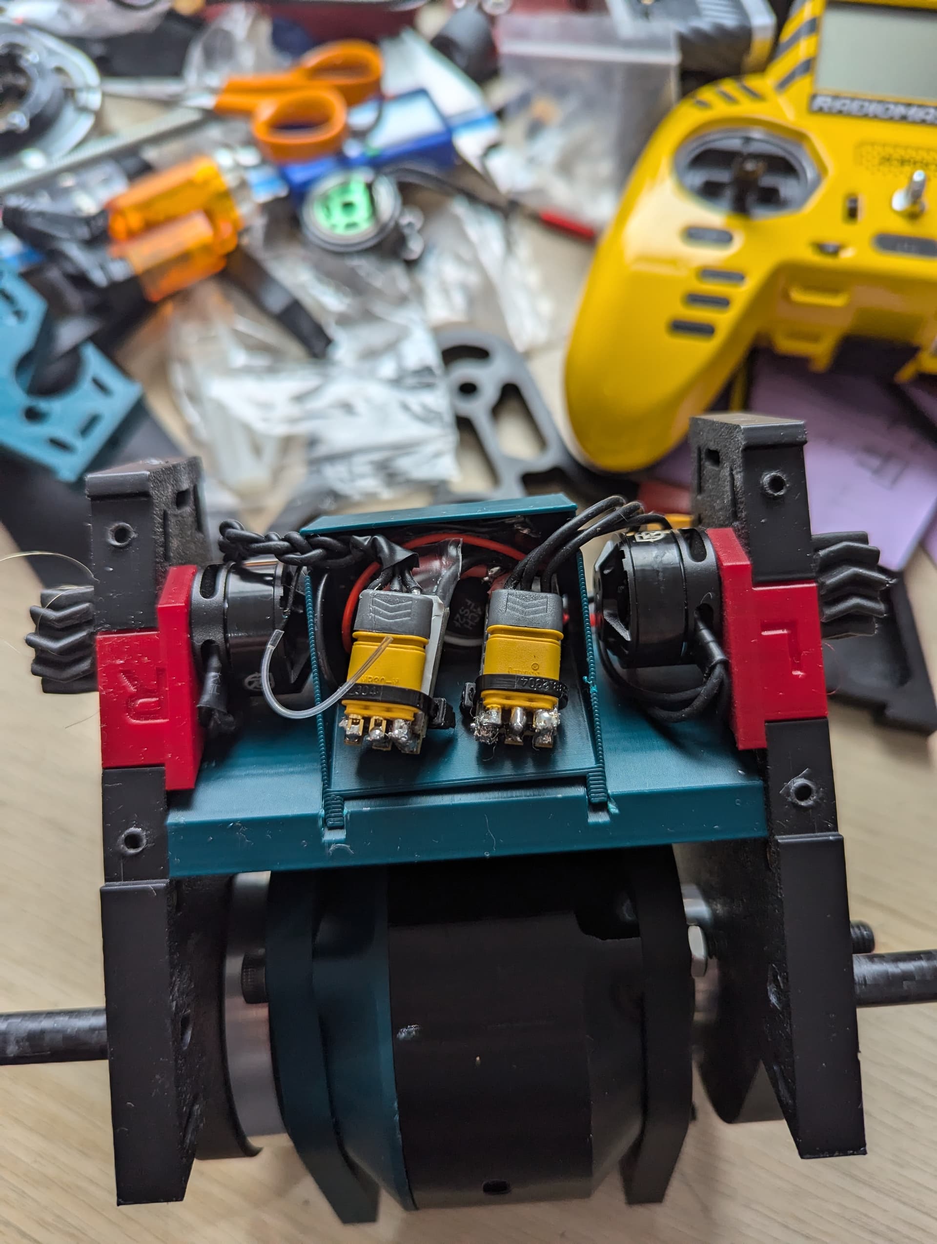
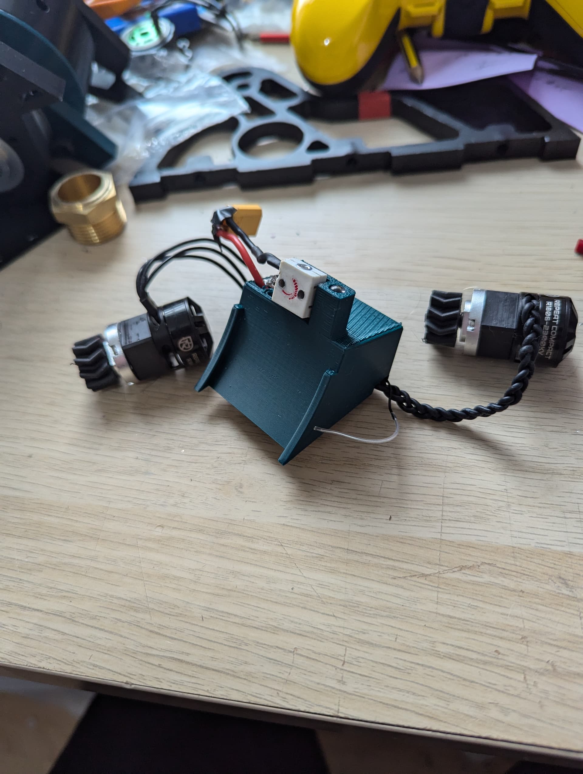
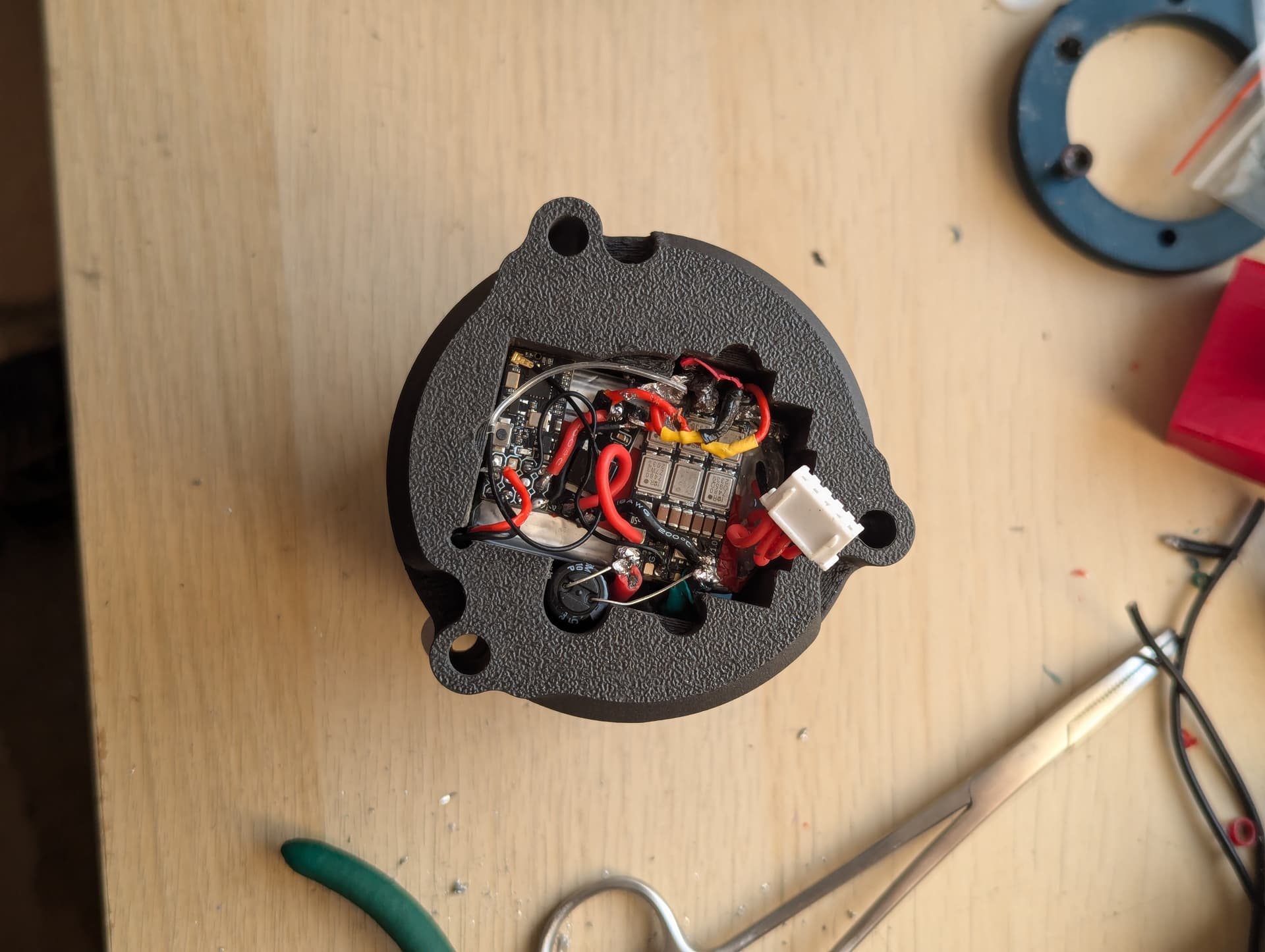
In terms of electronics, I want to make the drive motors unpluggable so I can slide them into jackhammer, so the rest of the electronics for the main body are going to be held in this little brick thing that slots in the centre of the bot. Ill be able to just swap this whole unit out at events if anything goes wrong and then fix it at home afterwards. You can really see here just how compact everything is in here – you know it’s compact when your wires all have to be cut to the perfect length and precisely routed. Other than that, this houses everything but the battery. Escs, bec, receiver, switch and light. Pretty neat I think. Once that’s in position all the electronics fit up in here with this little battery previously run in stratus.
That’s pretty much all I have for now. Lots still to do on the drum itself and then obviously I’ve got to make it all in my signature black and yellow.