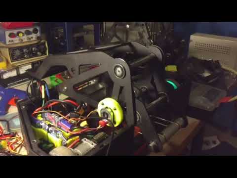
In the oh so distant past of 2017, when I was just getting started in the world of combat robots, I found this video on Facebook of a cam driven, spring powered hammer. Combat Robotics | Facebook
I saved it as part of an inspiration folder for the future, but I didn’t really want to build a hammer. A flipper on the other hand seemed far more interesting. So I went to YouTube and found a video of what I wanted. garage door spring winch powered flipper - YouTube
That video has been stuck in my head for almost 6 years, so I figured… Hey, I can do that, right?
After a quick google, the general idea is far from a new one. In fact, the Ask Aaron forum had whole pages dedicated to answering questions about this, including one with the exact video I had seen on YouTube and an older, but better designed version of a snail cam flipper. Most usefully, it had a template for the ideal snail cam shape, which I shamelessly downloaded for my own use. Combat Robot Weapons - The Ask Aaron Archives
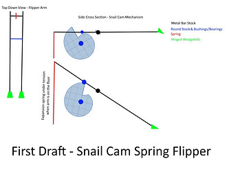
My actual designing begins, as I’m sure many of yours do, with quick random sketching. I threw this together in about 10 minutes to send to the rest of the team to show them the not-at-all-thought-out ideas I would drag them into building.
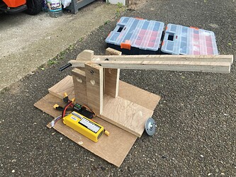
Once I had the team thoroughly convinced, or at least not completely opposed, it was time to get to work. I’m sure a lot of people would say the smart thing to do is open SolidWorks or Fusion 360 and make a CAD model. Not me! I don’t have any patience and want to see immediate physical results. So out to the garage I went, and in tradition Team Scrappers style, grabbed some scrap wood and set to work building a prototype.
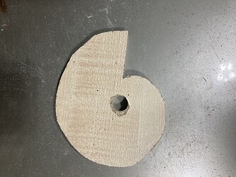
First up, the snail cam itself traced from the image on the Ask Aaron forum. Initially I made this way too big, so drew a line 1cm in from the edge all around and slimmed it down a little to the size in the picture below.
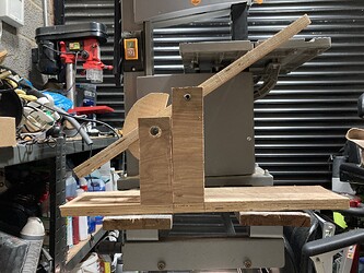
This was followed quickly by the first of three test flipper arms and a frame to attach it to, to give me the physical representation of the whole system with which to mess around and find the right geometry.
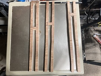
Of course you never get things right first time, after the aforementioned slimming of the cam and taking a few measurements it turned out I had basically built a seesaw. Pivot in the middle of the arm, near equal distance of movement on both sides. Now sure, I knew before I started that this first arm wasn’t close to the right shape. But it was the first piece of progress I could present to the team, and it wasn’t exactly impressive.
No worries, I’ll just make another arm of course. Having already built one, this time was speedy, all done and made in under 15 minutes. Move the pivot and the cam runner back a bit, see what happens. Well, I wasn’t actually calculating how far back I could move it. I figured I needed to leave space for the cam to fit in the gap between the runner and spring attachment, so I just moved it a few centimetres. Test again, measure again. Improvement! Not much, but some. I was headed in the right direction.
One more go, move everything as far back on the arm as possible, and actually check measurements rather than guessing this time. Ah-ha! Much more successful. The actual flipping side now moves twice as much as the spring side.
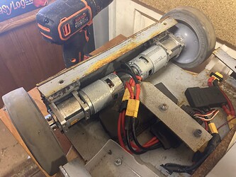
So that’s where we are after day 1 of building. A weapon test that has a geometry that I’m at least satisfied with, enough spares in the garage to build a chassis and drive system to go alongside it.
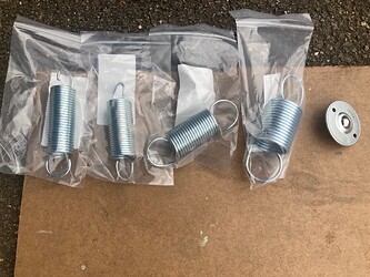
The only things left to figure out before we go all out on the building is which spring do we need to power the flipper, how large a ratio gearbox is needed to turn the cam drive, and which events can we take it to when it’s built. As I write this I’ve just heard that Extreme Robots aren’t hosting featherweights this year, and most other events are hard to get to from the east coast of Norfolk.
