Barber Surgeon 4
I went into this design process with a few clear aims:
- Firstly was a hubmotor. Morgan had more than sold me on the potential benefits to weapon effectiveness, which was on top of the benefits I already understood about simplifying the weapon system and saving both space and weight. This would also allow for a curved or angled weapon arm to prevent the hammer arm from limiting my bite.
- Following on from that was the weapon geartrain. My current gears were both narrow and of a lower MOD than I would have liked. Not only had this made the actual transmission of force through the gears quite concentrated, but it had also made it difficult to mount the pinion gear securely - all this time I only had space for a single M3 grub screw and square nut, and that had to change.
- Finally was some general design rationalisation. Five events and over a year into Surgeon’s hammer saw era, and I’d really got to grips with the parts of the design that worked, and the parts that didn’t. Given the design remained fairly consistent between v2 and v3, now was the chance for some meaningful steps forward.
The CAD process started differently from every other Surgeon, in that the weapon came first. Really, this is the ‘correct’ way to do robot design, but since I’d been getting to grips with an alternative drive system, that had, until now, been the starting point. The Repeat Antweight hubmotor was selected for the task, due to availability and high praises from the other Scottish hammer saw builders. In terms of weight, cost and availability, it seemed ideal, especially since making my own would probably not be any cheaper.
To this, I will be mounting a 106mm 3mm Hardox disc. At the hubmotor’s 1200Kv, on 4s, this would max out my tip speed at 250mph. Just like Dolos, this disc will be sharpened, and currently weighs in at ~65g.
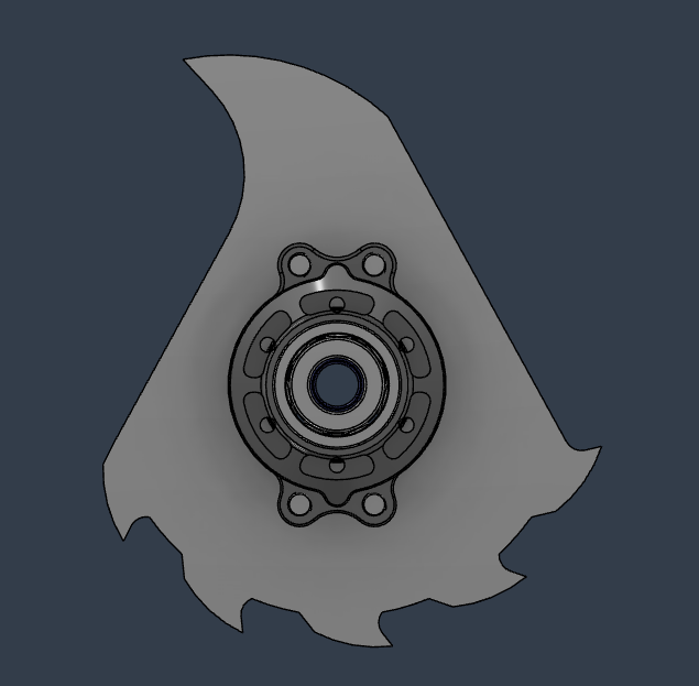
Aggressive… Most… Aggressive.
A single curved 10mm RG1000 arm followed, then some nylon MOD 2.5 Double Helical Gears at 3:1. The pinion gear now has three M4 square nuts along it’s length. I chose a cantilevered motor setup purely for motor placement. As discussed before, the arm motor and front drive motor are very close in this design, and a single arm allows me to raise up the arm motor on the opposite side without fouling the weapon arms themselves.
How am I lookin’?
Another rationalisation step was to alter the chassis shape. Omni bots are always going to use space inefficiently, but I felt there had to be a better way to wrap the bot around the components than the current triangle, despite it’s aesthetic charm. A slightly flared rear end to accommodate the battery, and an arrowhead shaped baseplate was my initial approach but…
Uhm… Is that a robot in you prints or are you just happy to see me?
…it ended up starting to look kinda… phallic? Any attempt to salvage this baseplate design became a bloated mess. Since an omni has guaranteed empty space, for perhaps the first time, I had to start thinking about aesthetics instead of pure space efficiency. Ultimately my solution was one that many of us can relate to in life - be more Thomas Yau. Using an approximation of PMXL’s baseplate as a starting point, I slowly adjusted angles and cut material until I found something I was happy with…
I’m thinking maybe an orange TPU this time out?
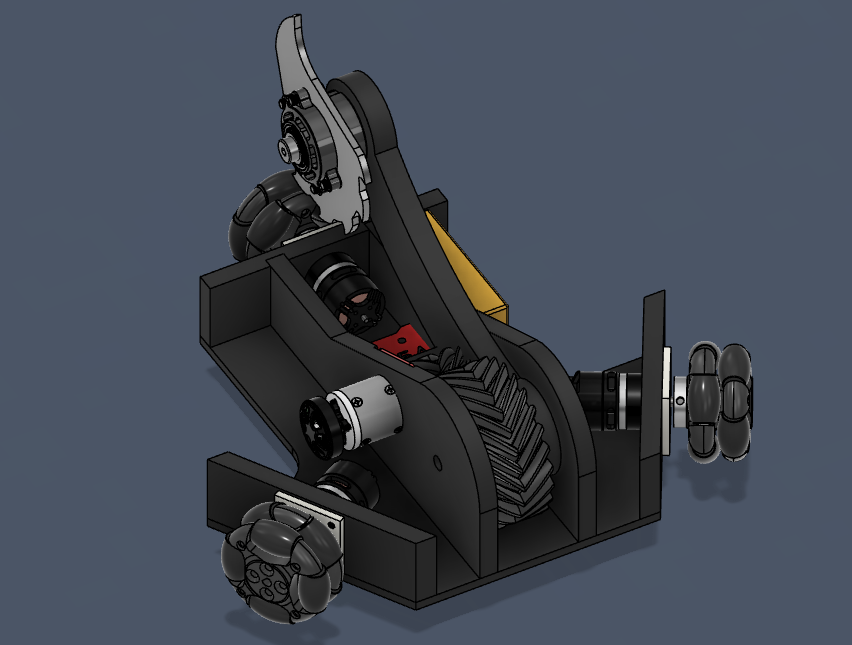
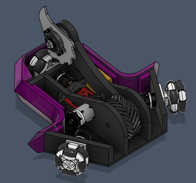
I realised just how much I liked the angular shape of previous Surgeons, and this is what I ended up with. The major parts are closely packed, but with enough tolerance. I’m thinking of adding magnets, too. You can see the mounts for two in the ‘lids off’ angle, just next to the front drive motors, and there will possibly be some rear ones too, to keep the tail planted on a hit.
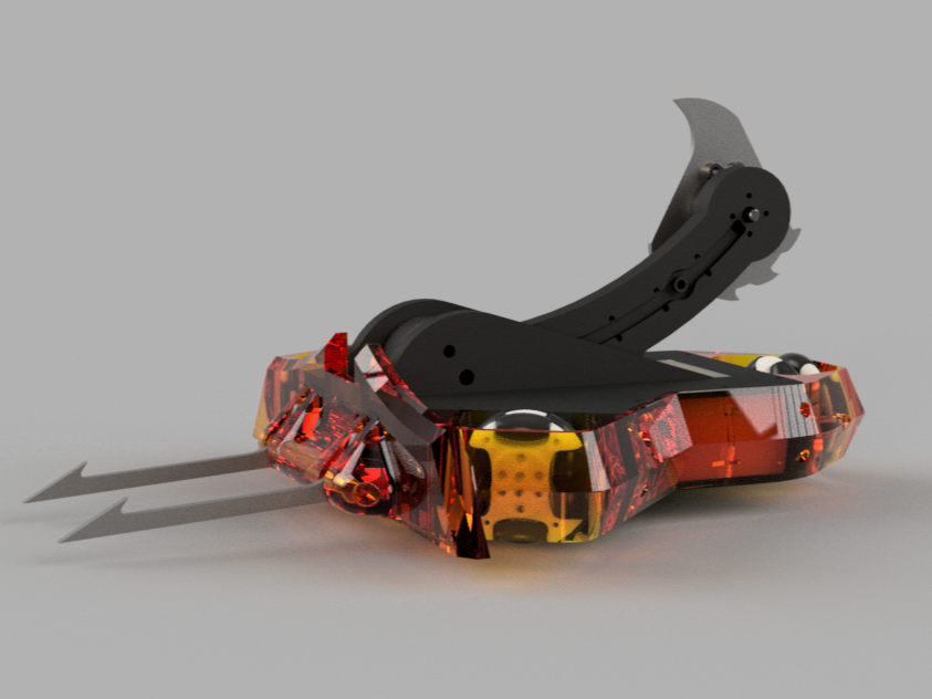
Fusion doesn’t render orange translucent material very well, apparently.
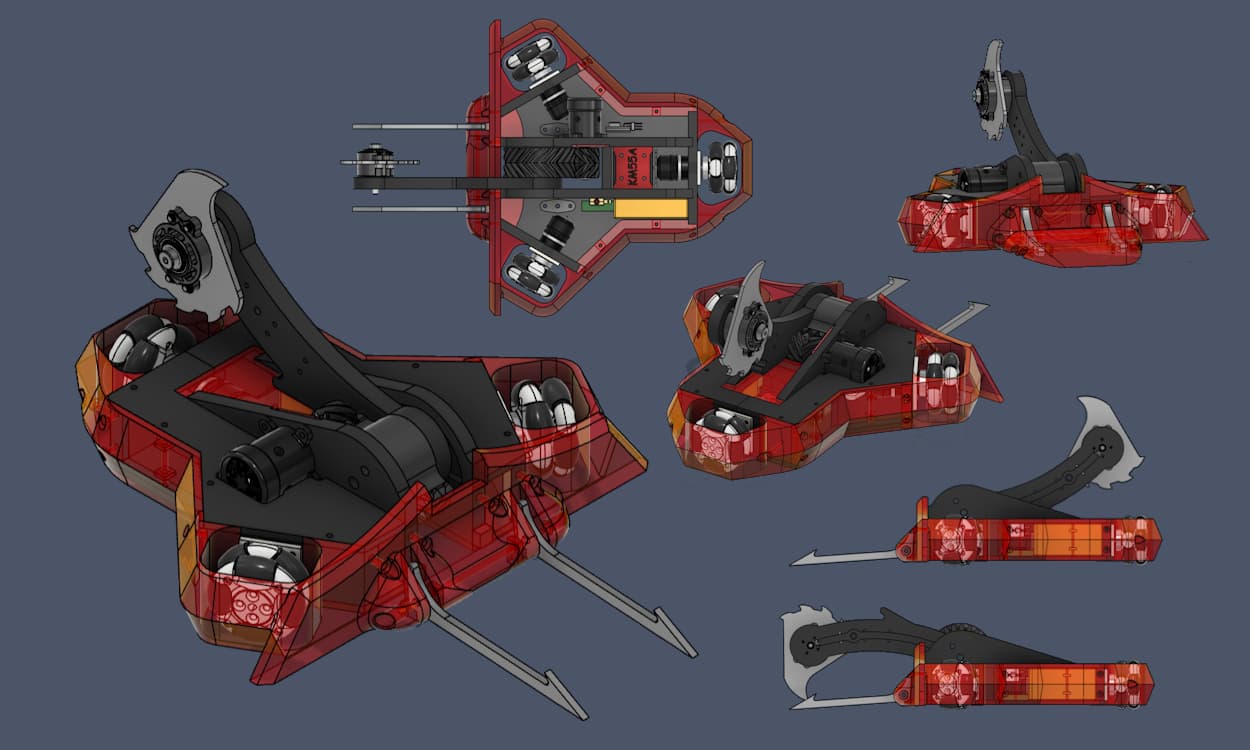
The TPU armour ring is now in four parts to avoid any heat inset nuts and tricky mounting angles. The front piece includes the plough and front drive armour loops, which mounts with woodscrews to the front and sides. A left and right ‘bumper’ piece is stacked onto the same side mounting screws, and runs as far as the tailpiece. The rear armour is another separate piece, for ease of printing and replacing.
Just like the new Surg3on forks, which are designed to be compatible, the forks here will flop and lock just before the robot can get high centred on them. I’m trying some long 4mm forks out, but I still have some old Surg3on locking forks, unmodified, that I will try to see if the new gear setup can self right where the old one couldn’t. I’ll draw your attention to the new duck bill wedge (top right) on hardox hinges.
Gonna tell my kids I built this as a cluster.
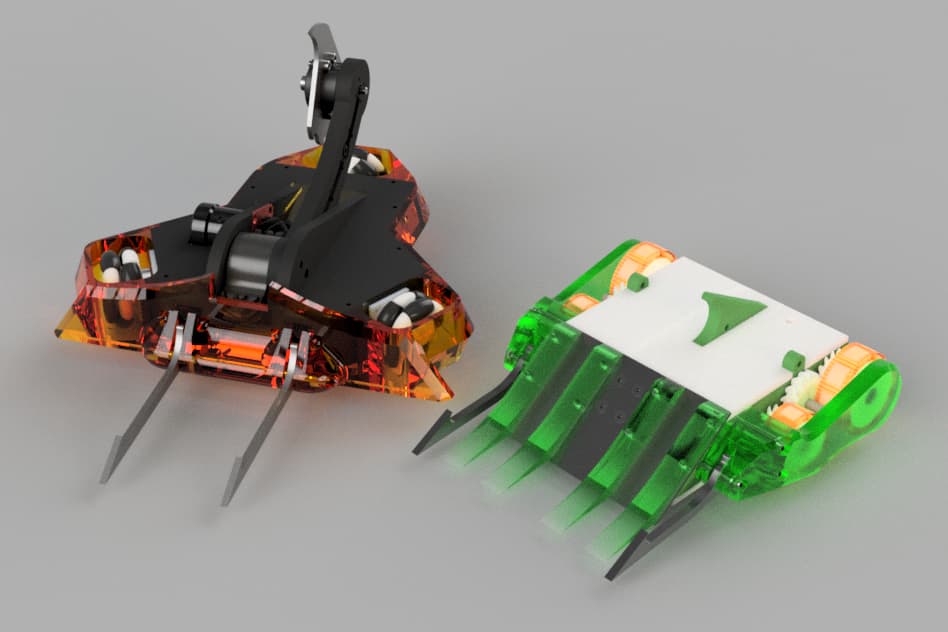
Size wise, it’s the same wheelbase, near enough, as Surg3on, but with the chunks taken out of the sides and some lower profile bulkheads. I’m doing some weight calculations, but you can see just how tiny the new Crossblow is! Drive will remain exactly the same, unless I invest in some rotalink gearboxes, as the current drive system is quite jumpy. Apart from a few fasteners and motor covers, this is it so far! I’m considering building Crossblow first, since I already have some of the forks on order, Surg3on is still functional, and the Repeat parts will take a while to arrive.
If you’ve read this far, thank you very much! I hope you’ve enjoyed this look back, and I’ll post again as soon as I have any decent updates. Any design feedback would be gratefully received, and I hope to see you in the arena soon!