The chronicles of Luchador 1 through 3

Delving into the code and the Arduino IDE was an interesting experience for me. I’m not very experienced at Arduino stuff but have done a bunch of coding for other things (websites and game dev mostly) so it wasn’t completely alien.

A quick search online and I easily found an established and relatively robust approach to decoding the pwm from the TX which I successfully copy and pasted into my codebase
402919bbe07931968ccc2d4627042e23

And so I set about coding up my control loop.
I initially coded up a rough P controller - using only proportional control. This essentially looked at the difference between the current position and the target position and if over a set amount applied full beans to the motor and if under that threshold it scaled the power down proportionally to difference.

This worked well in bench testing but lacked torque - a fuller implementation of PID would be needed. However all the reading I was doing on the subject and the guidance I was receiving from Dr brushless himself (Gareth Barnaby) was telling me I should be testing and tuning any PID control as part of the fuller weapon mech - to ensure that it’d behave sensibly under the correct kind of loads.

I’d have to get designing and building the robot it was going to go in…

I knew I could probably just about squeeze it into mk3 - but after two years or so of dealing with some pretty annoying underlying design decisions - I felt like the time was right for a fuller redesign.

So work began on mk4

3 Likes

That’s what attracted me to the worm drive too, but the biggest problem I had was friction and efficiency; all the numbers looked great on paper but the friction forces induced by all the side loads in the gearbox cause it to just not perform very well under load. It ended up not being practical due to packaging requirements (surprise) but I might visit it again some time.

I’m also very familiar with implementing PID loops and I hope the tuning process wasn’t too painful :sweat_smile:

Going into the design of Mk4 I wanted to bring some of the lessons learnt from running The Chilli Daddy into Luchador while also making serviceability a bigger focus. With that in mind I had a few design priorities entering the project:

  • easily and quickly hot swappable front ends (all previous Luchador this was a bit of a nightmare and an absolute time sink at events)
  • easily removed drive motors. Past iterations had required substantial tear down to remove/replace the drive motors and while not a job I had to do super frequently - when I did need to it would also be a huge time sink at events
  • big over sized rear wheels to allow it to reverse out of most positions/stacks
  • really leverage both the CNC router and printing to make fabrication simpler

There were also a number of things I loved about mk3 that I wanted to preserve:

  • the handling: Luchador mk3 drove fantastically and I wanted to retain that
  • front end geometry: mk3s default fork set up and general front end geometry has proven to be effective against a variety of opponents and I have a good number of it’s forks in stock so keeping that the same felt like the play

After a week or two of iteration I had settled on most the key decisions, a billet hdpe chassis, TPU armour/front end, belted wheels. And I ended up with something along these lines:

In tandem with this early design phase I was prototyping my drive - knowing I was gonna need off sized wheels I wanted to lock in the gearing and belt length stuff early so I could firm up the details around it in the rest of the design. I generally don’t trust calculators for timing belts and use them as a starting point and then iterate using printed test jigs till I’m happy - as you can see it’s very much an iterative approach!
Eagle eyed viewers might notice some of these early cads had gear driven rear wheels, this is something I had done a bit of on some iteration of mk3 and was initially an idea to share rear wheels with TCD, however I overlooked the key fact that this made the wheels go in opposite directions so was quickly abandoned :rofl:

I had recently revamped the antweight version, Luchador Jnr and also wanted to bring in some of that style to the aesthetics.

Already using the same red TPU, adding the poly wedge and mask decal was the obvious play and left me with this:

While I was instantly enamoured with the look - I was also concerned about the likely hood of verts getting engagement on the wej. So I revised the lifter arms to set it back as far as feasible to try and keep it out of harms way - leaving me with this:

While visually, very different from mk3, overlaying the two chassis shows how actually similar they are in terms of wheel placement, footprint and front end geometry

Happy with the design and unable to test my weapon servo until the chassis was built I pressed onto fabrication.

6 Likes

So this post might be a bit disjointed as it’s mostly me talking about details that I can find photos of :rofl:

Moving onto the fabrication, the big job initially was machining the billet chassis. This required ops on both sides and so I had to make a peg board to properly align it all out of some MDF and lifter shaft offcuts.

This was a first for me - while TCD’s billets had an op on the off side for the weapon gear pocket, they were pretty simple due to being concentric circular ops - all I would do is machine the billet with just a pilot hole the size of the router but on the main side, then flip it and screw it down in position with the bit in the pilot hole. No real angular alignment needed. Luchador chassis however was much more involved hence the peg board.

But it all went pretty smoothly and I was left with a nice chassis. Ready to be cross drilled using 3D printed drill guides.

I printed all the TPU parts, I’ve spent a lot of time getting my shitty old ender dialed in on TPU (switched to dual gear extruder, some custom parts to get that to play nice with my direct drive mod etc) and have started getting really nice but slow AF results. Although I have to do nasty big ass brims because my bed has some annoying dips.

I switched to a TPU grabber arm. The 6mm hdpe ones I’ve used up to this point have been great, but I hoped that adding a bit more flex here would soften shock loads on the servo


And printed and cast the new wheels for the drive train.


I then started on assembly, one feature I added for this iteration was drop in drive mounts, these are machined hdpe and drop into keyed slots to facilitate easier removal.


The whole billet is designed around the custom servo. The lifter uprights are made from deeply pocketed 20mm hdpe because it looks cool. These are machined down to 8mm thick tabs that house a square nut and press into pockets in the billet and provide the threads for the rear wheels. Kinda extra but fuck it, why not!? :rofl:
The front wheels thread into barrel nuts in the front protrusions on the billet, and the TPU front ends key onto the chassis and cross bolt.

The mask decal and wej are 3mm polycarb, with the design printed onto reverse adhesive stickers and stuck to the underside of the poly. I added some tiny dots to the design that line up with the mounting screws to help get it all on straight and then trimmed down the excess sticker afterwards.


The weapon was intended to be linkage driven, dialing in this linkage was very annoying due to its tendency to foul either a shaft or the servos large diameter through the flow of movements. Making a set up that avoided this while still having sensible angles for torque transfer was a challenge.

And so here is it, Luchador Mk4

All that was left now was to iterate on the servo codebase and get the weapon working. Champs was only a couple of weeks away at this point. So pressure was on a bit and I really needed this next phase to go smoothly…

(Spoiler alert: it did not in fact go smoothly)

7 Likes

So now we’re about a week and a half before champs - the intended debut of Luchador mk4 and I still didn’t have a working weapon. Those of you that know me, know that I like to be prepared early - so this was a big source of anxiety for me. Dealing with that would have to be a big focus.

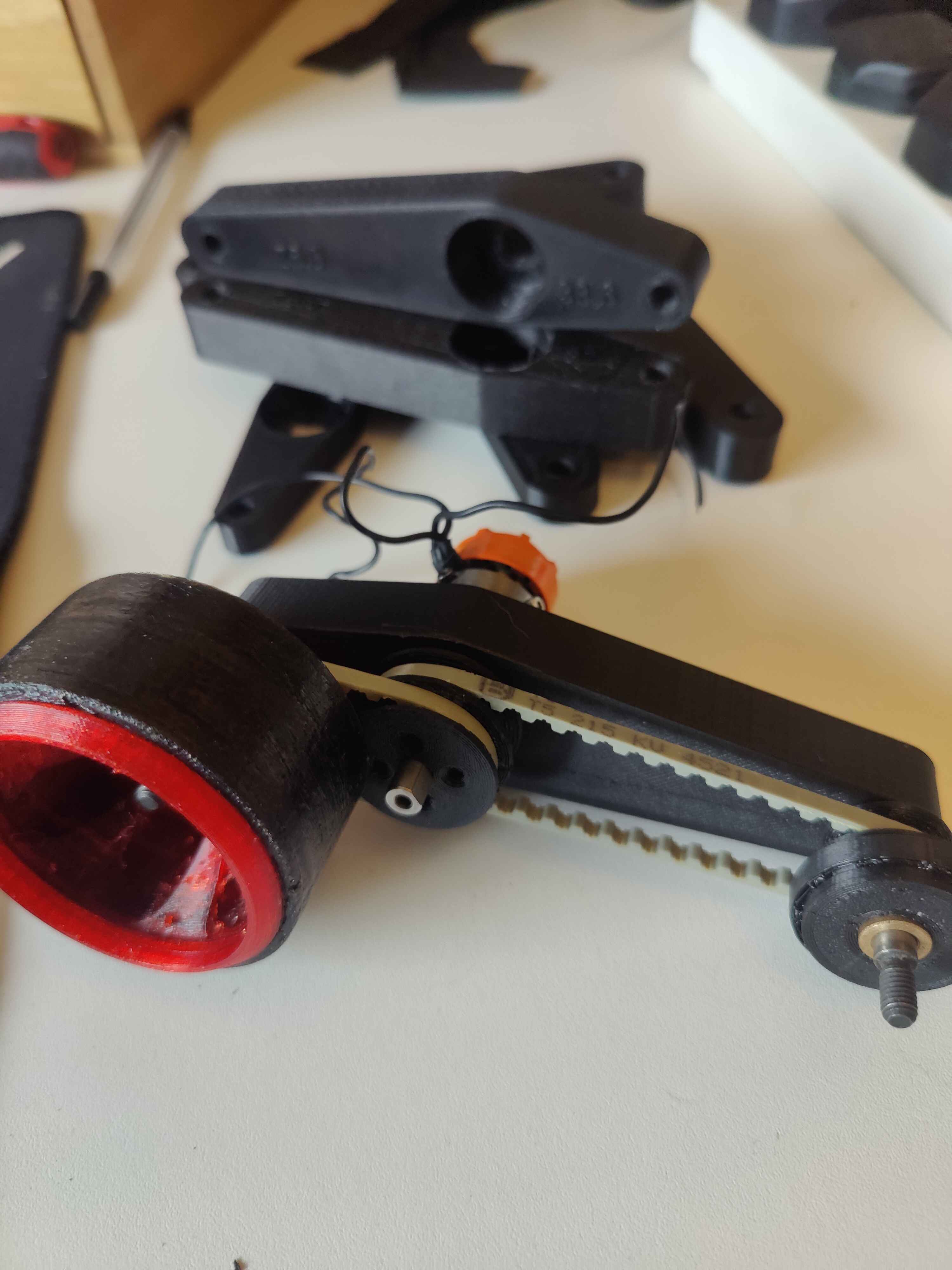
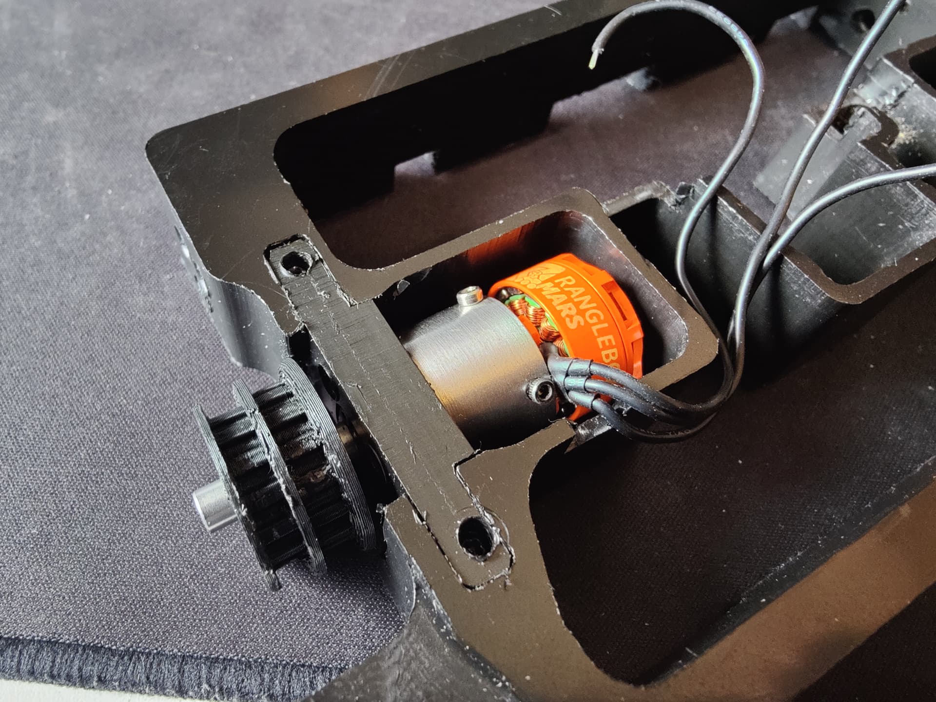
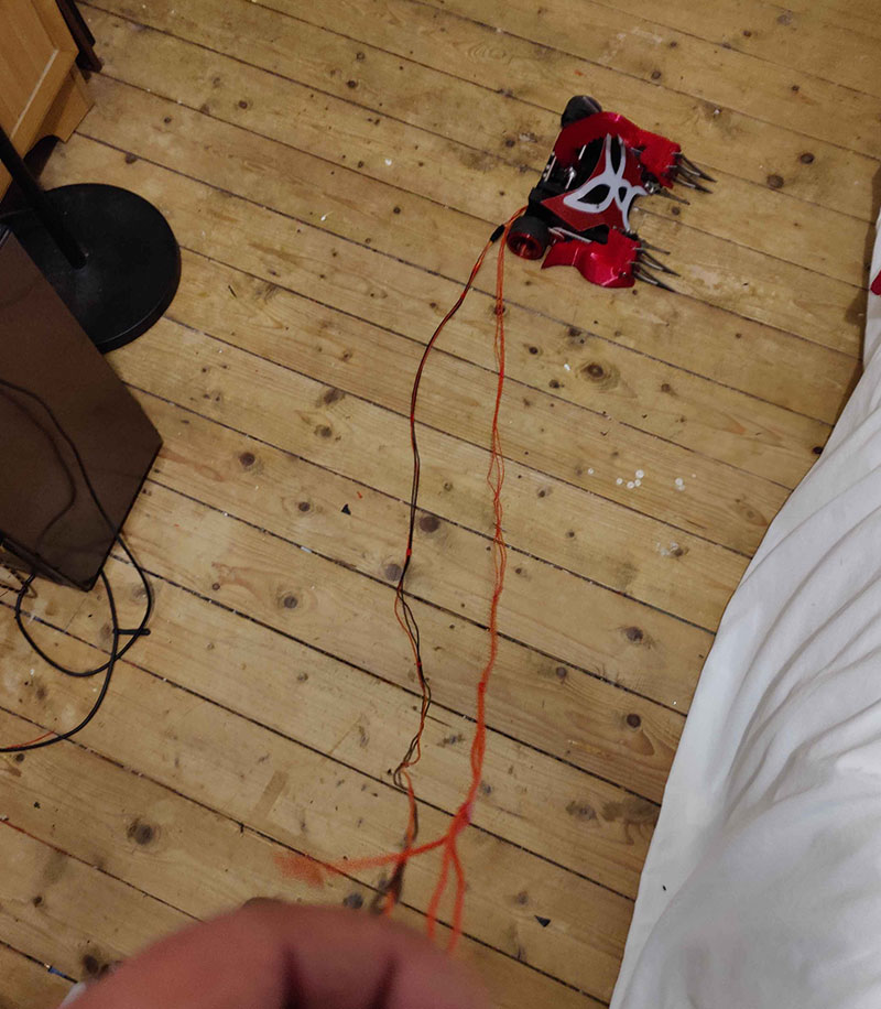
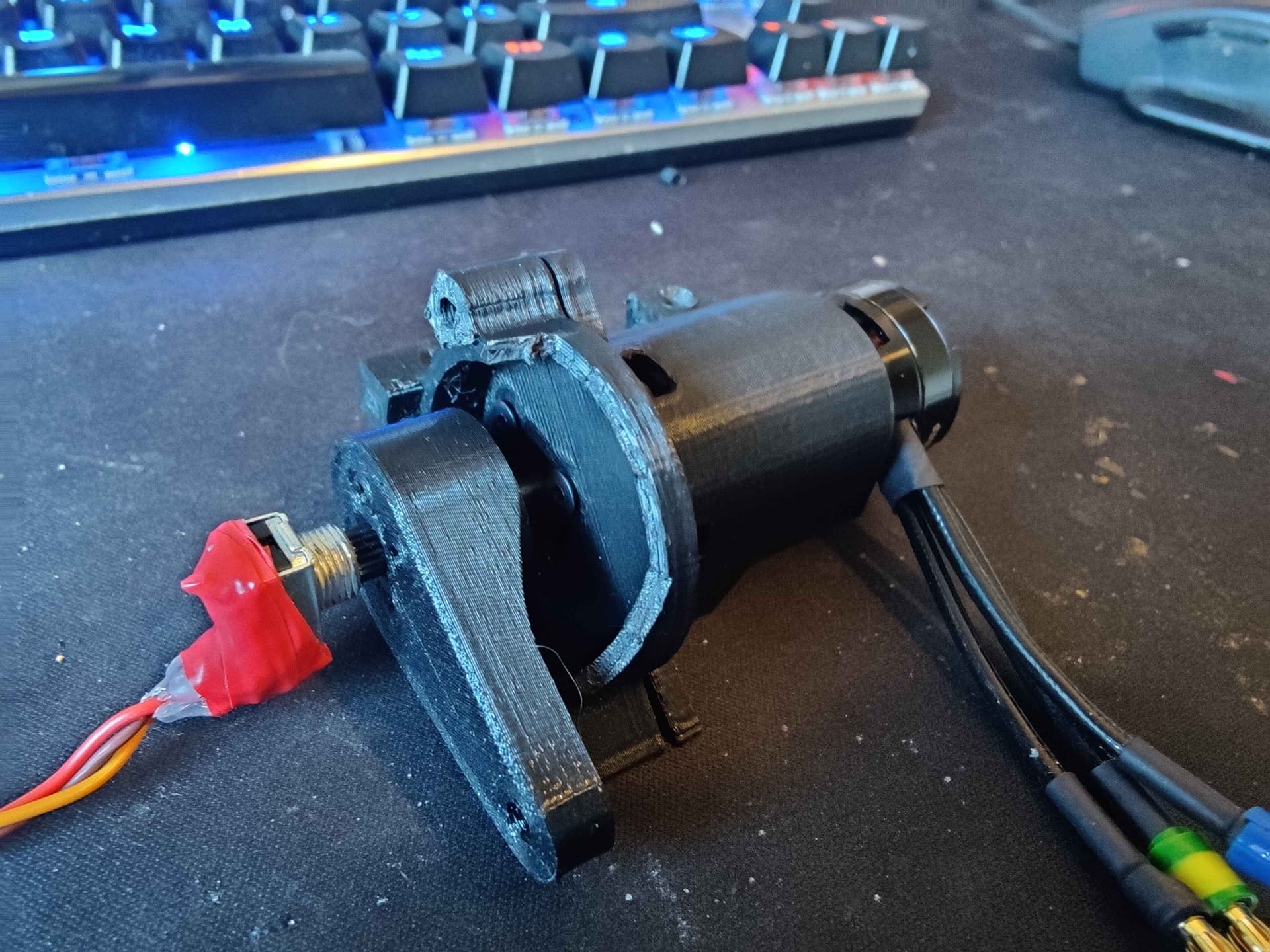
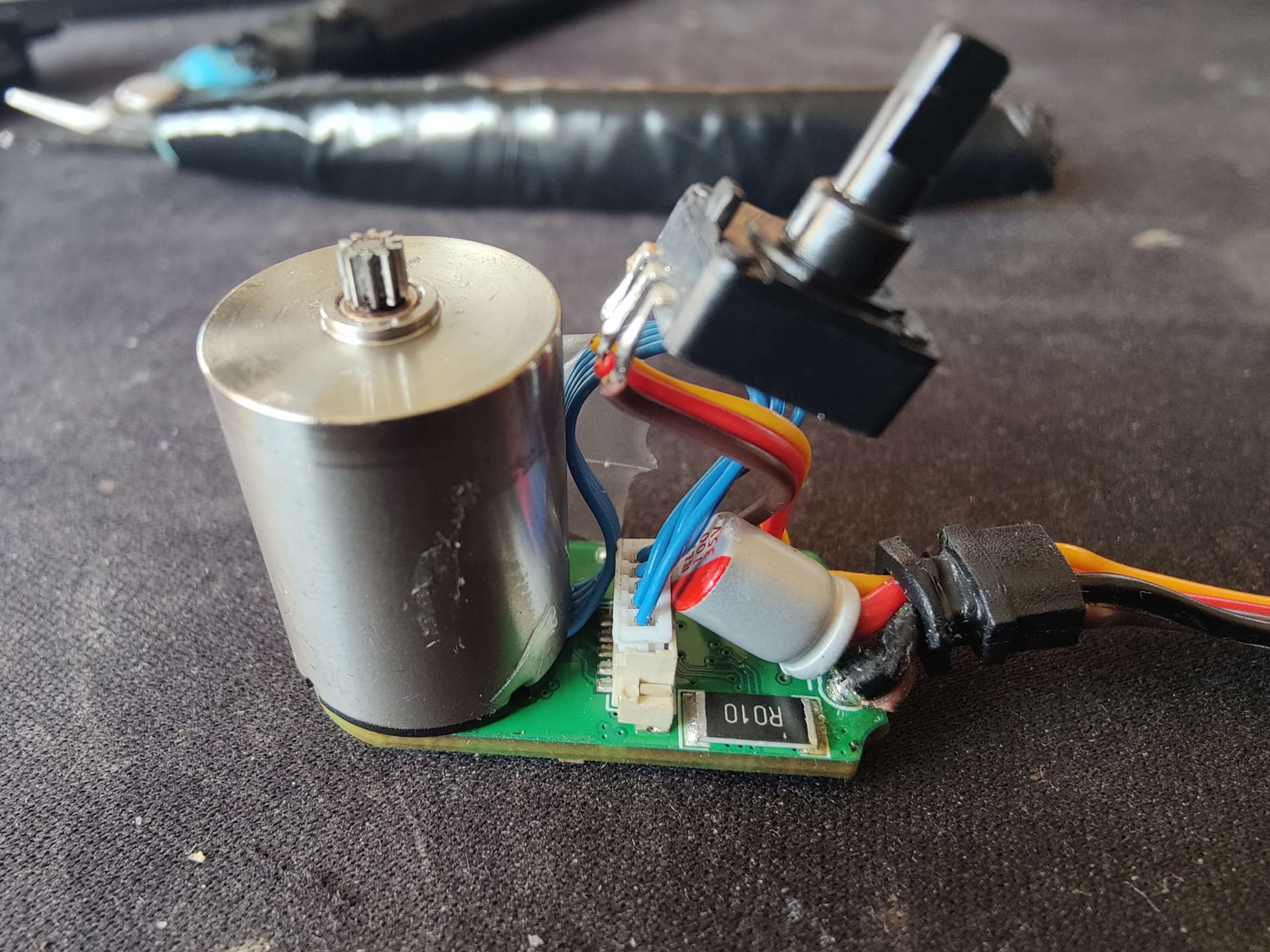
I started by making some extension leads for the motor and pot so that I could have the robot firing its weapon on the floor with the all the electronics on my desk next to my PC.

I then started work on the code base. I laid the early foundations/frame work for it all first. On first boot, the arduino would take a reading of the pot - set that as the bottom range of motion limit (as that is where the lifter would be orientated when the locking bar is in), then apply an off set and set that as the top range of motion limit.

It’d then enter an arming mode, where it would output 1500 pwm to the ESC for 3secs to give the AM32 Esc a chance to arm up. After that it would enter “Servo mode” where the PID loop ran.

I had a toggle set up to be able to switch between that and a back up “gearmotor” mode where the arduino just outputs the same PWM to the ESC that it receives from the RX incase the pot dies or becomes misaligned etc. I also added a few error catching states that would make the arduino output 1500 to the ESC for failsafeing etc.

Moving on to the PID set up. First I tried integrating the PID Library and using that, getting it installed went smoothly however I struggled when I got onto trying to tune the PID values as it always wanted to start with a minimum output - meaning full beans reverse! - I think this is because it doesnt know if the output is reversible (like on this gear motor) or not (like on an oven heating element).

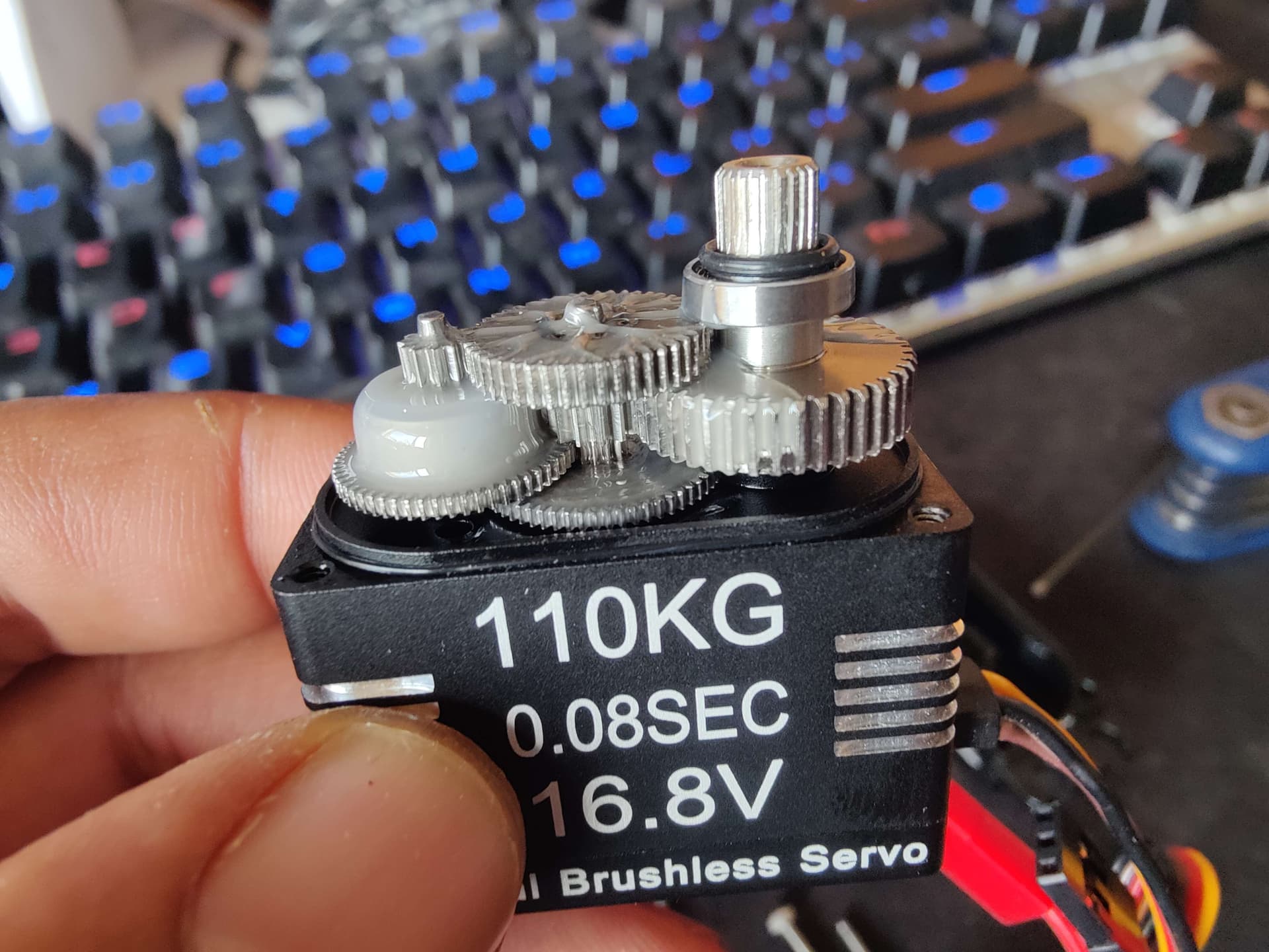
During these initial experiments the servo cracked a mod1 10t output gear. This was a little alarming but was a very old gear that had seen a lot of use on luchador mk3 and 2 in the past - so I didnt think too much of it and ordered two more fresh ones from technobots. This put a hold on things for a few days.

Once the new gears arrived and I had one installed and Loctited up - I had a house call from Dr Brushless himself Gareth Barnaby to assist with the PID. Dude is a wizard and stripped out all the PID Library stuff and wrote a custom PID implementation from memory with no references in no time flat - we then went through and tuned the servo/PID variables on the desk and got it moving with purpose and behaving sensibly. At this point Gareth walked off into the sunset having done basically all the hard work on my code base :rofl:

Here’s a little video of it working and of the back up gear motor drive in action:

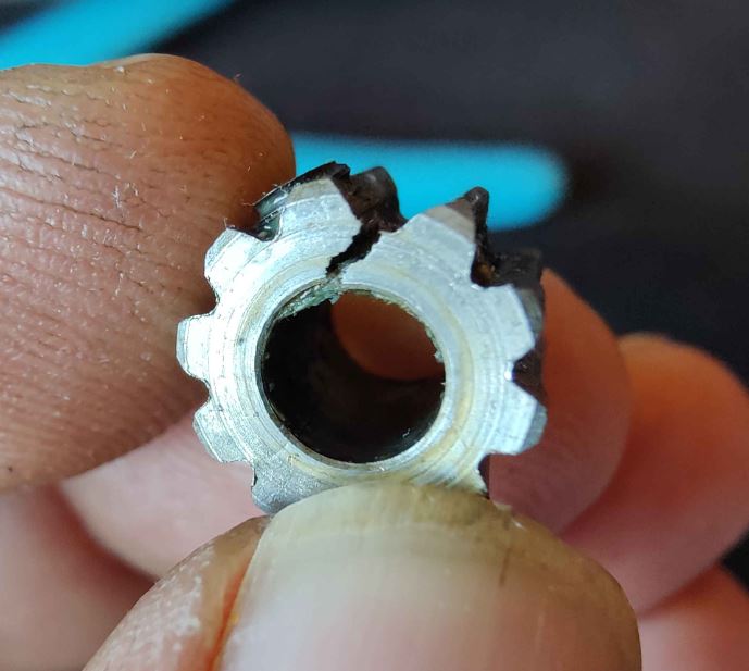
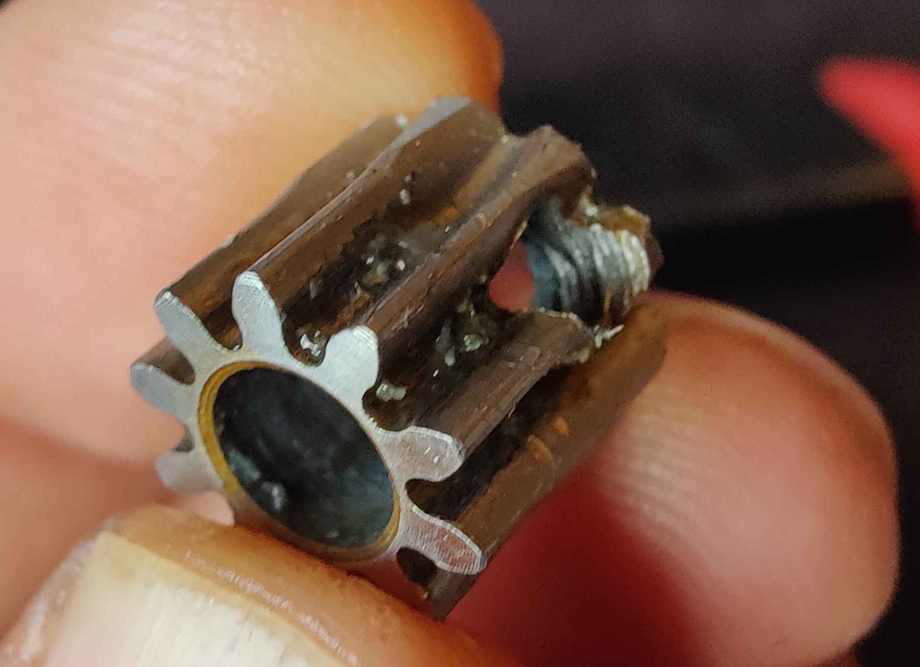
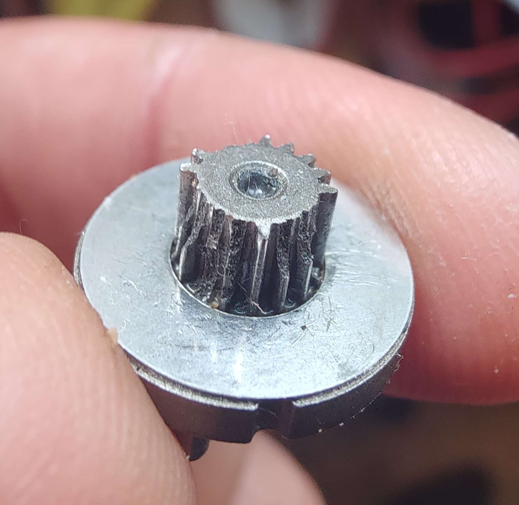
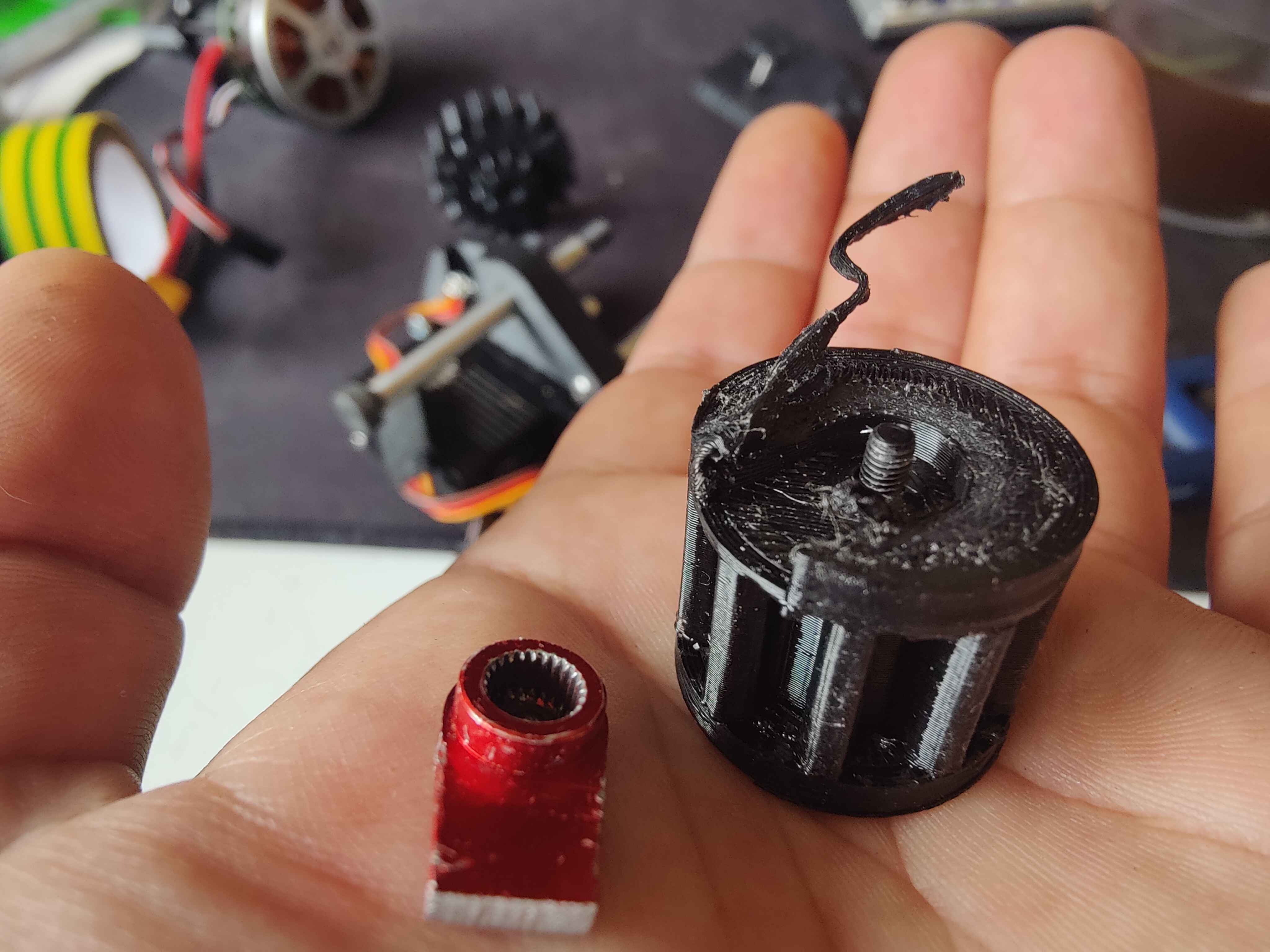
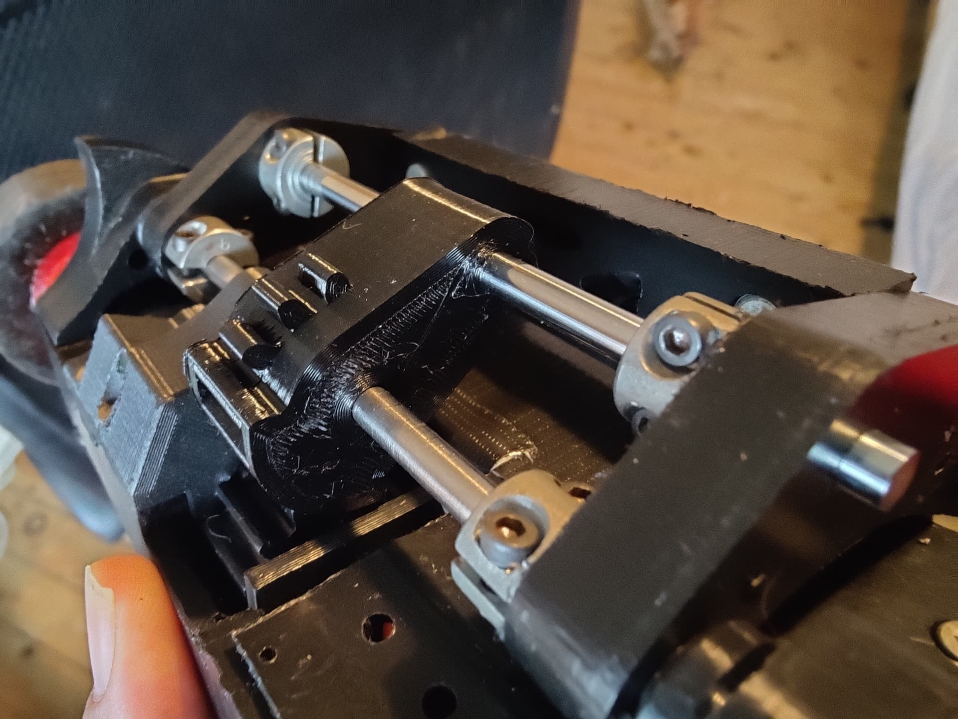
So onto testing in the robot, this started out reasonably and then there was a clunk and then motor spinning noises with no discernible movement on the weapon. Oh shit - was the pinion slipping on the motor??? - I stripped the servo down and found I had killed another output gear…


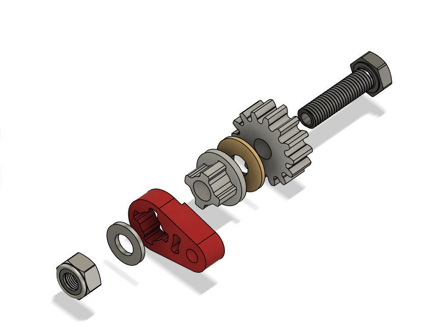
In my efforts to make the servo as compact as reasonably possible, I had designed it around these small 10t mod1 gears. Because theyre so compact there is no proper boss and a lot of the threads for the grubscrew are essentially in the teeth of the gear. As the PID was torquing the motor back and forth rapidily, the grub screw was acting like a lever and splaying these teeth outwards - until they just let go of the grub screw altogether.

image

Being about a week away from champs at this point and finding no gears that would fit while being more substantial - I attempted a bit of a long shot hail mary to try and save the servo.
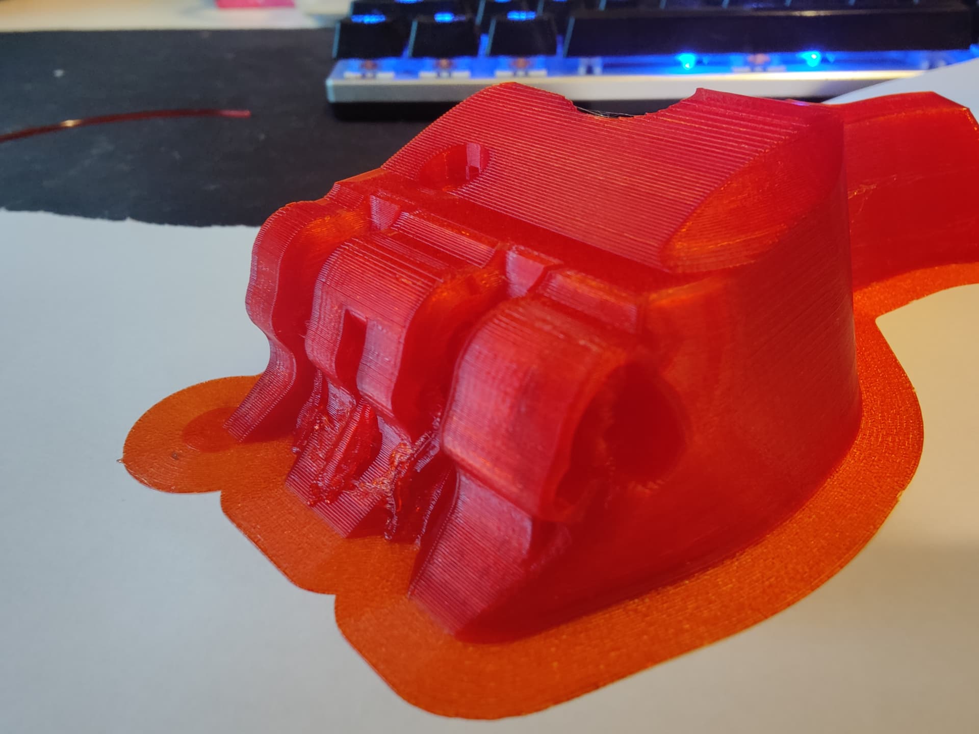
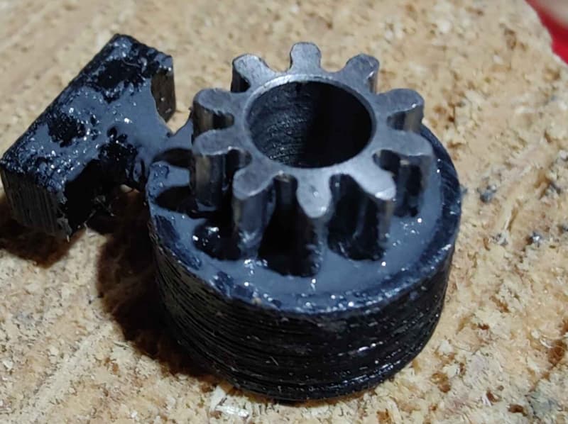
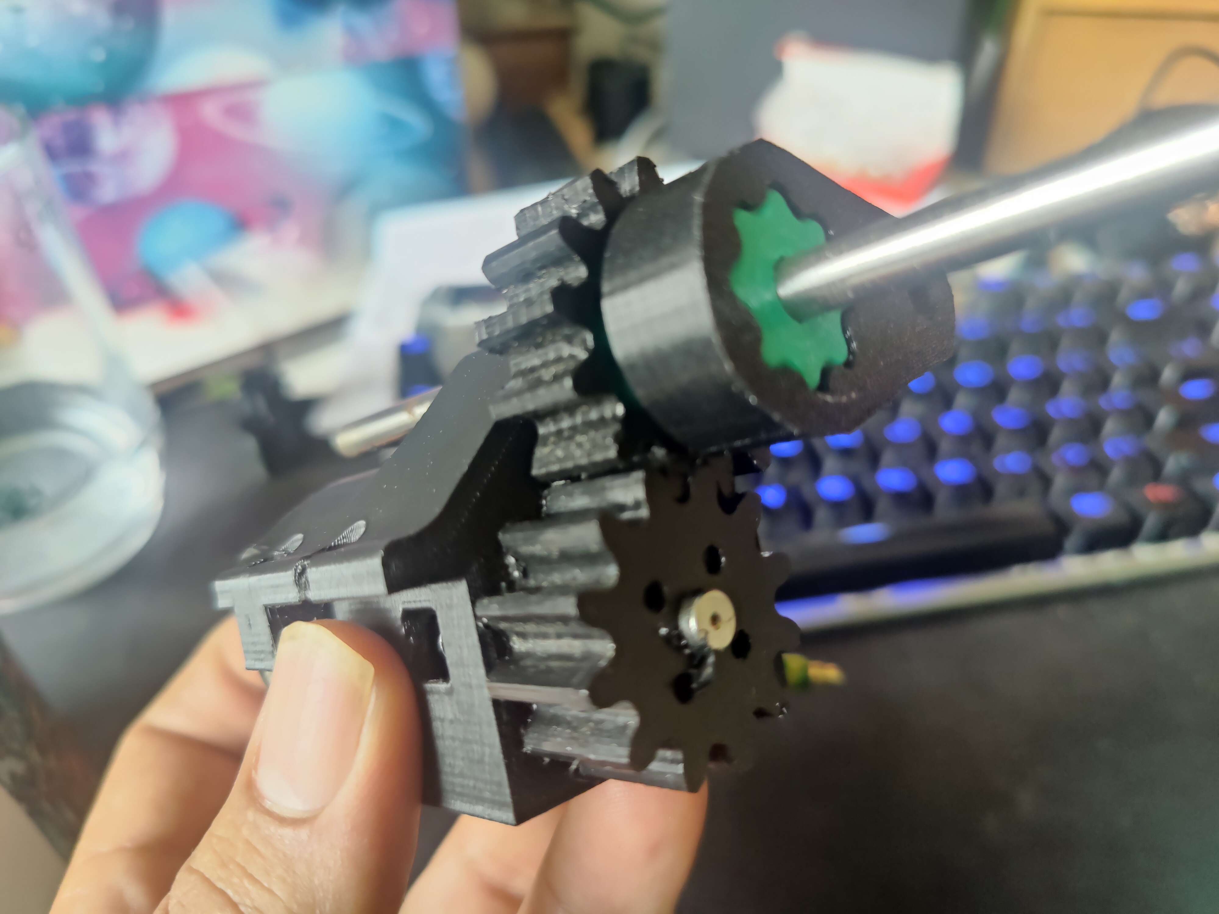
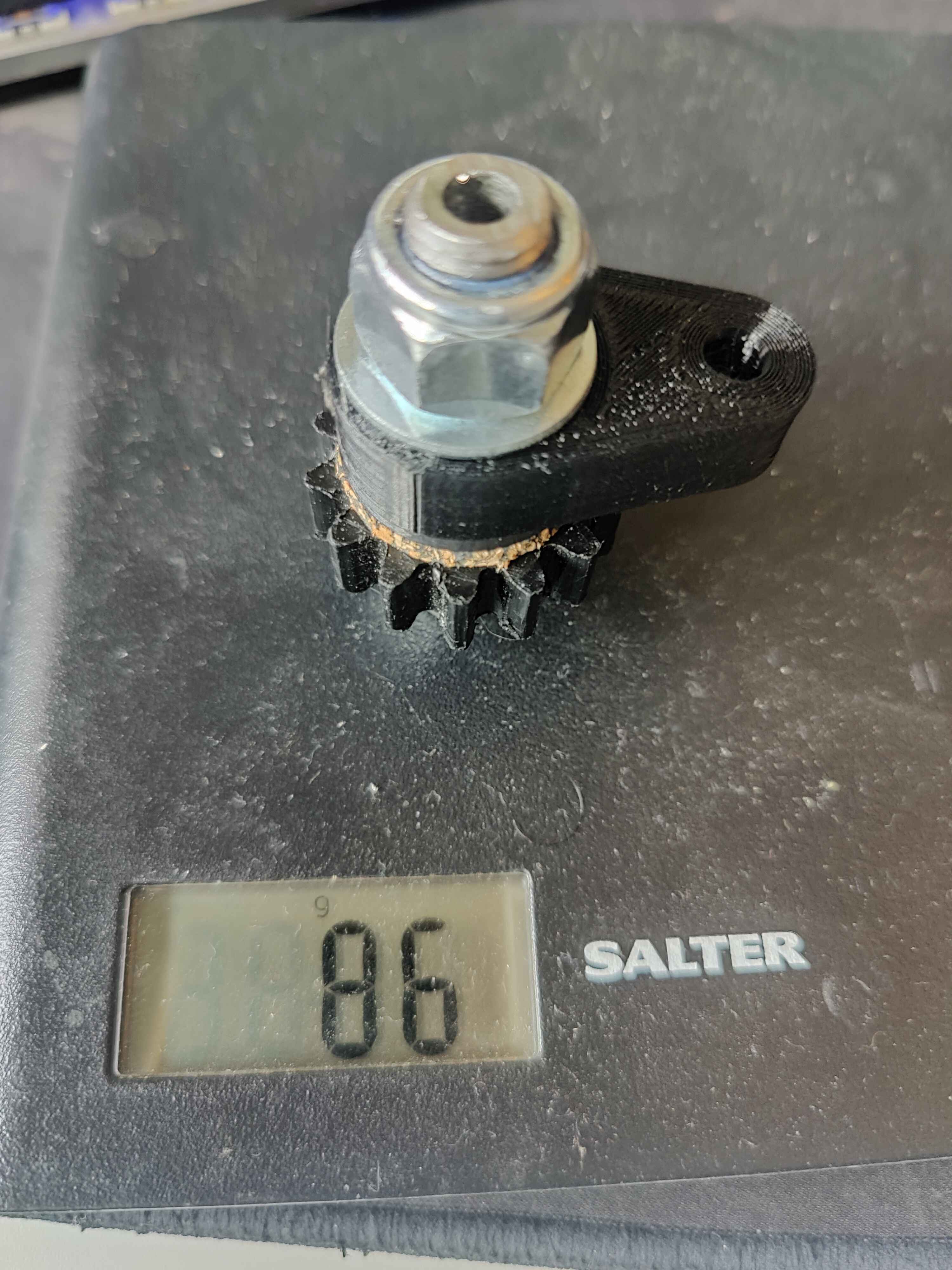
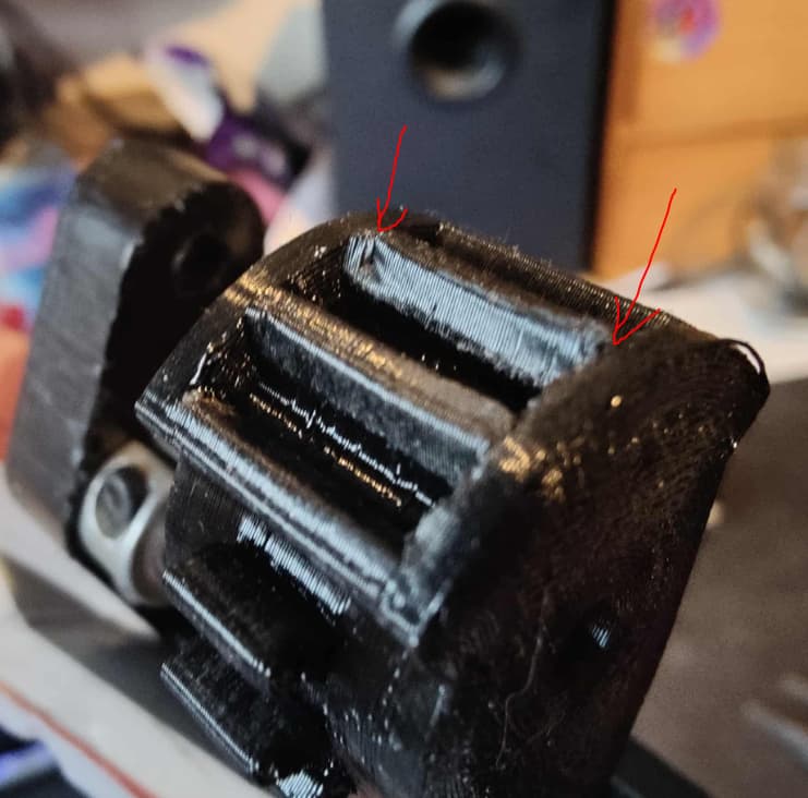
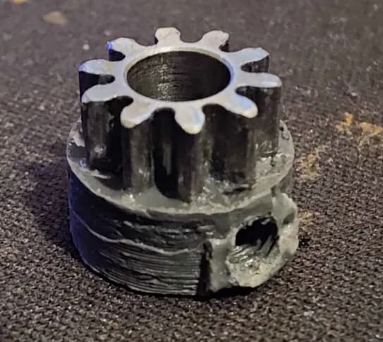
I tried casting a reinforcing ring of JB weld onto the one good gear I had left. (I was most certainly loosing my mind a little at this stage)

A day later and I had this absolute cursed pinion: :rofl:
image

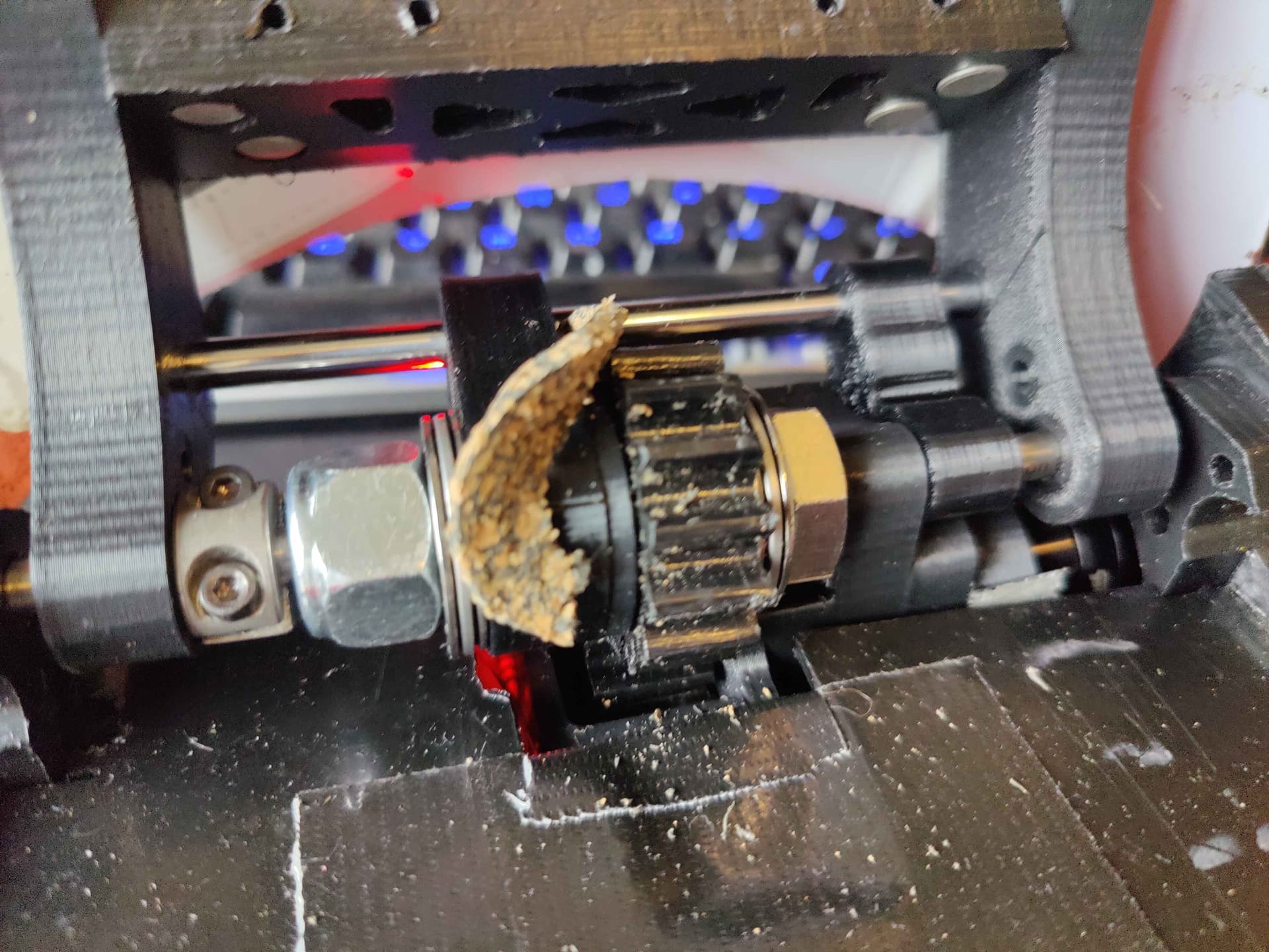
I reinstalled and continued testing the servo. The JbWeld pinion seemed to be holding as I iterated on the PID settings - however the servo while very happy suplex-yeeting my 1.5kg test weight really lacked the torque at slow speeds to do the controlled grab and lift thing - which was the whole point of the project to begin with. I had thought that a combined 290:1 reduction would have been enough to overcome the brushless rpm x torque power curve but apparently not - or possibly I had other inefficiencies going on?

And then… Crack and Spin noises happened - and the JB Weld pinion finally gave up too. (although tbf it did last about 5 times longer than the plain one did in testing).

At this point it was mid-week of the week running up to champs, I had no weapon and no way of making the servo plan work in the timeframe. My general internal monologue at this point was essentially: “AAAAAAAAAAAAAAAAAAAAAAAA!”

A big last minute pivot was gonna be needed!

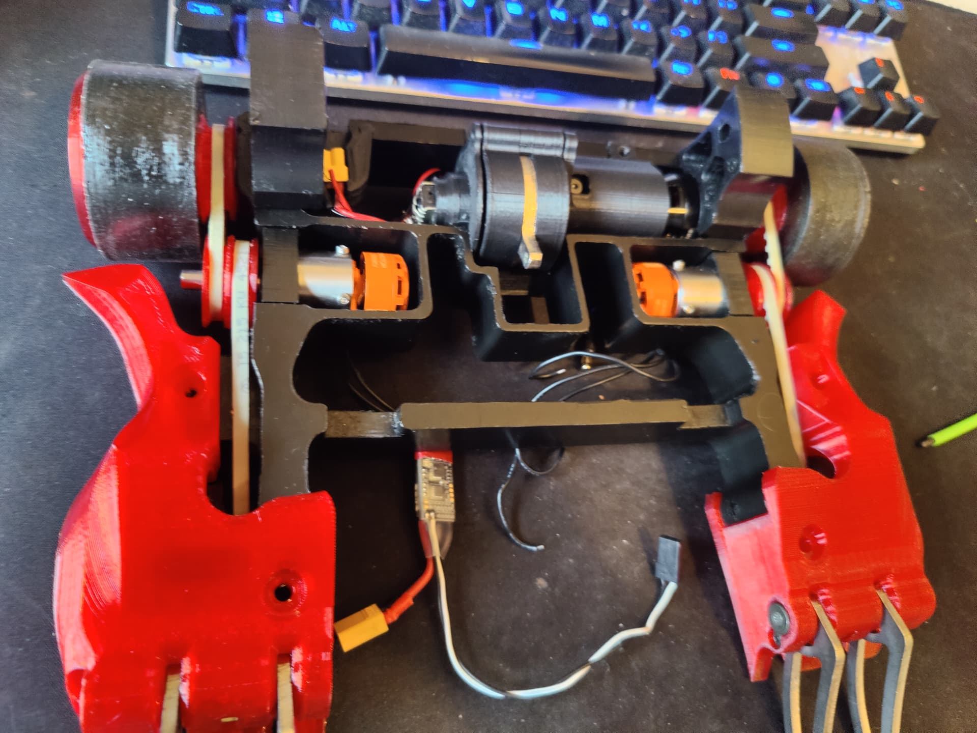
The servo output and external reduction was dead on arrival. But the gear motor and arduino were installed and all still functional. However, even with the extra reduction stage the ring gear provided the set up lacked the slow controlled torque that Luchador needed to do what I feel Luchador should do - elegant grab and lifts - but at this stage on the Wednesday before champs I just needed to make something viable.

So (very) reluctantly - I made the decision to sack off the grab and run Luchador as a conventional lifter/flipper. The torque requirements on conventional lifters are much, much lower than on grab and lift - and on flippery things there is no need for slow speeds - so this should work with the brushless power curve.

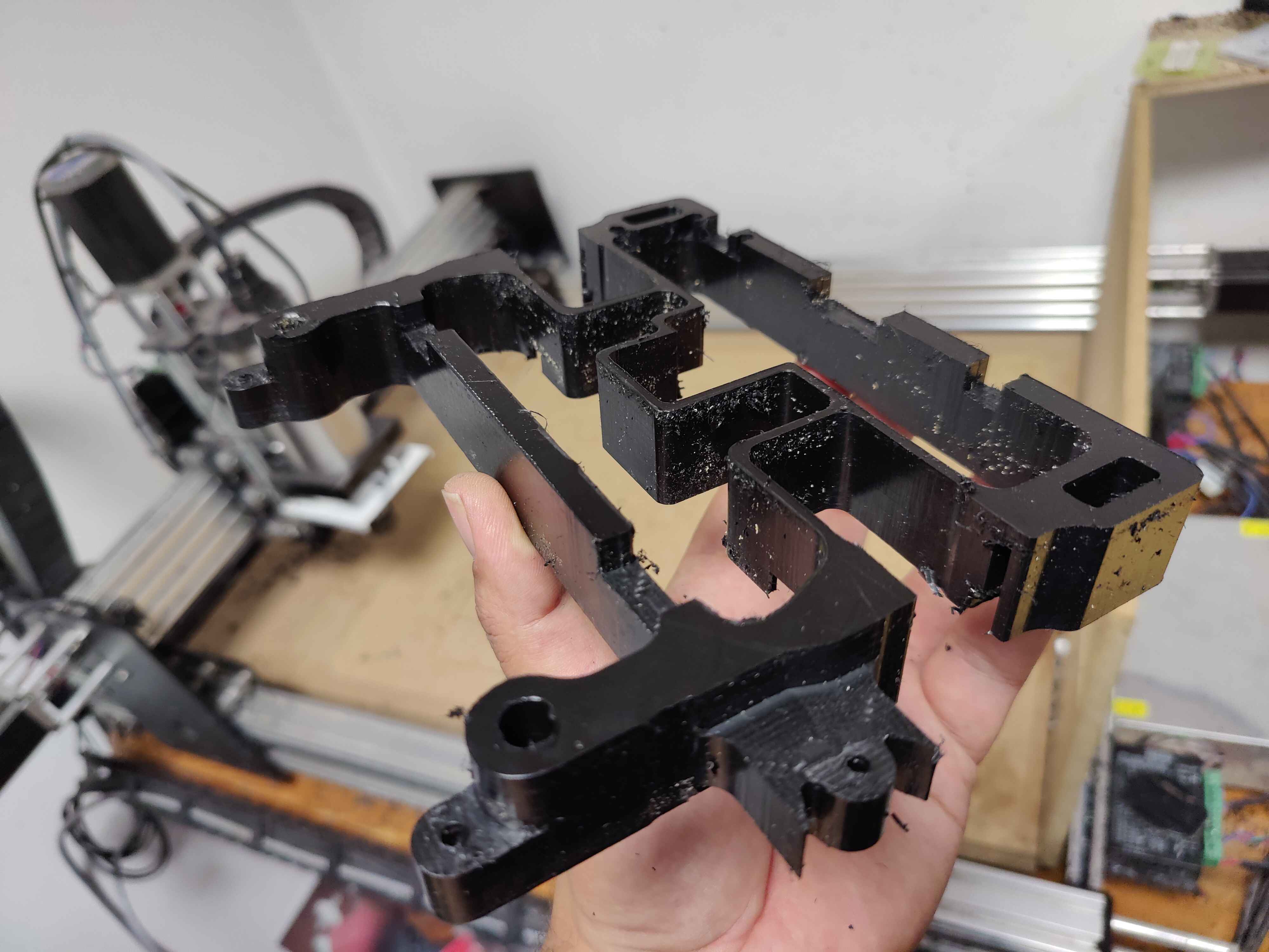
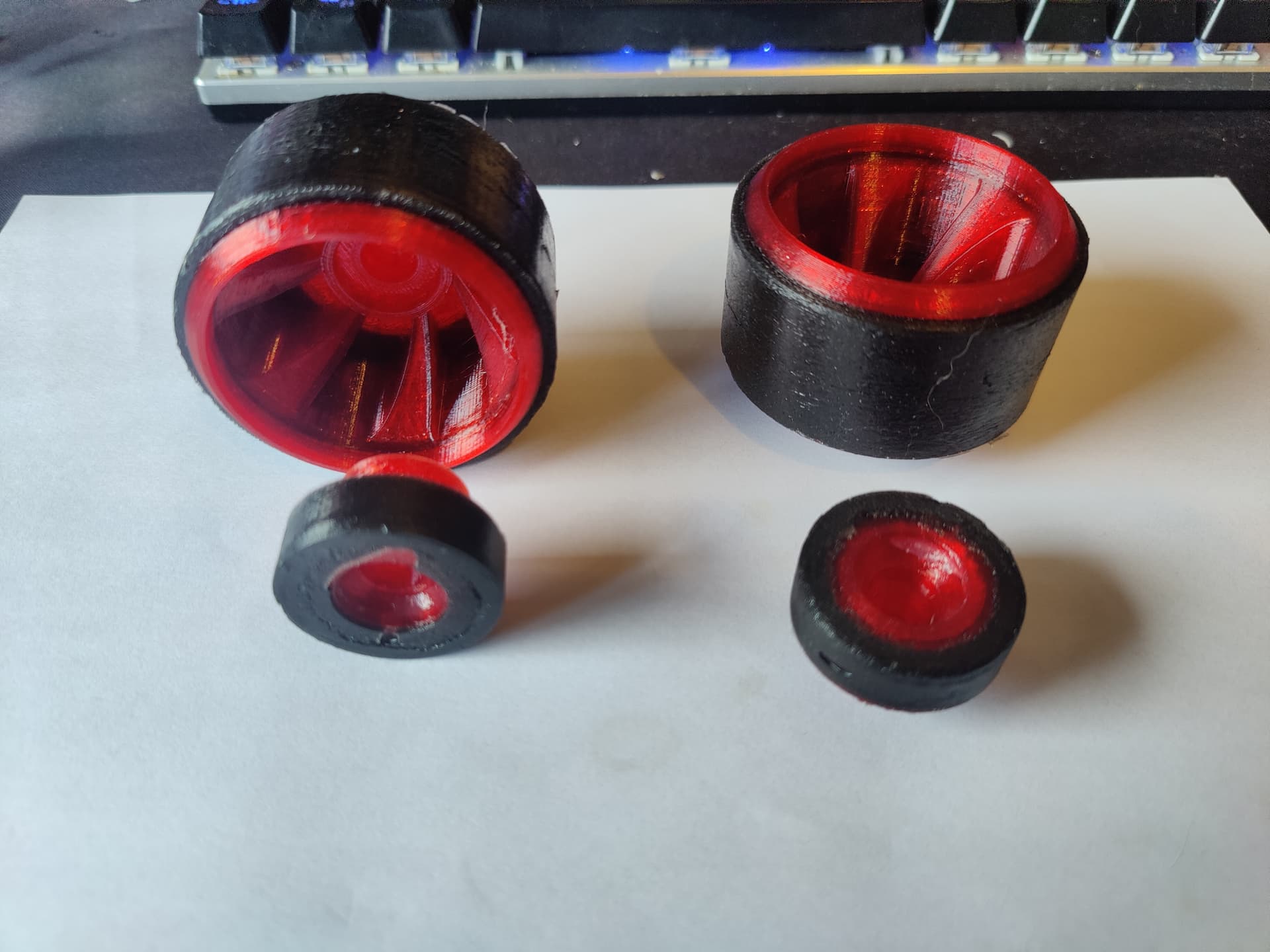
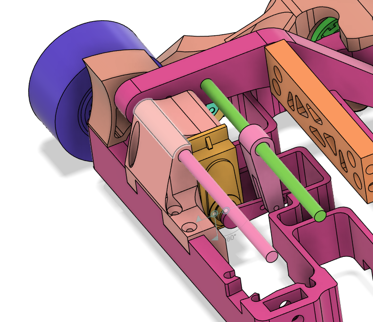
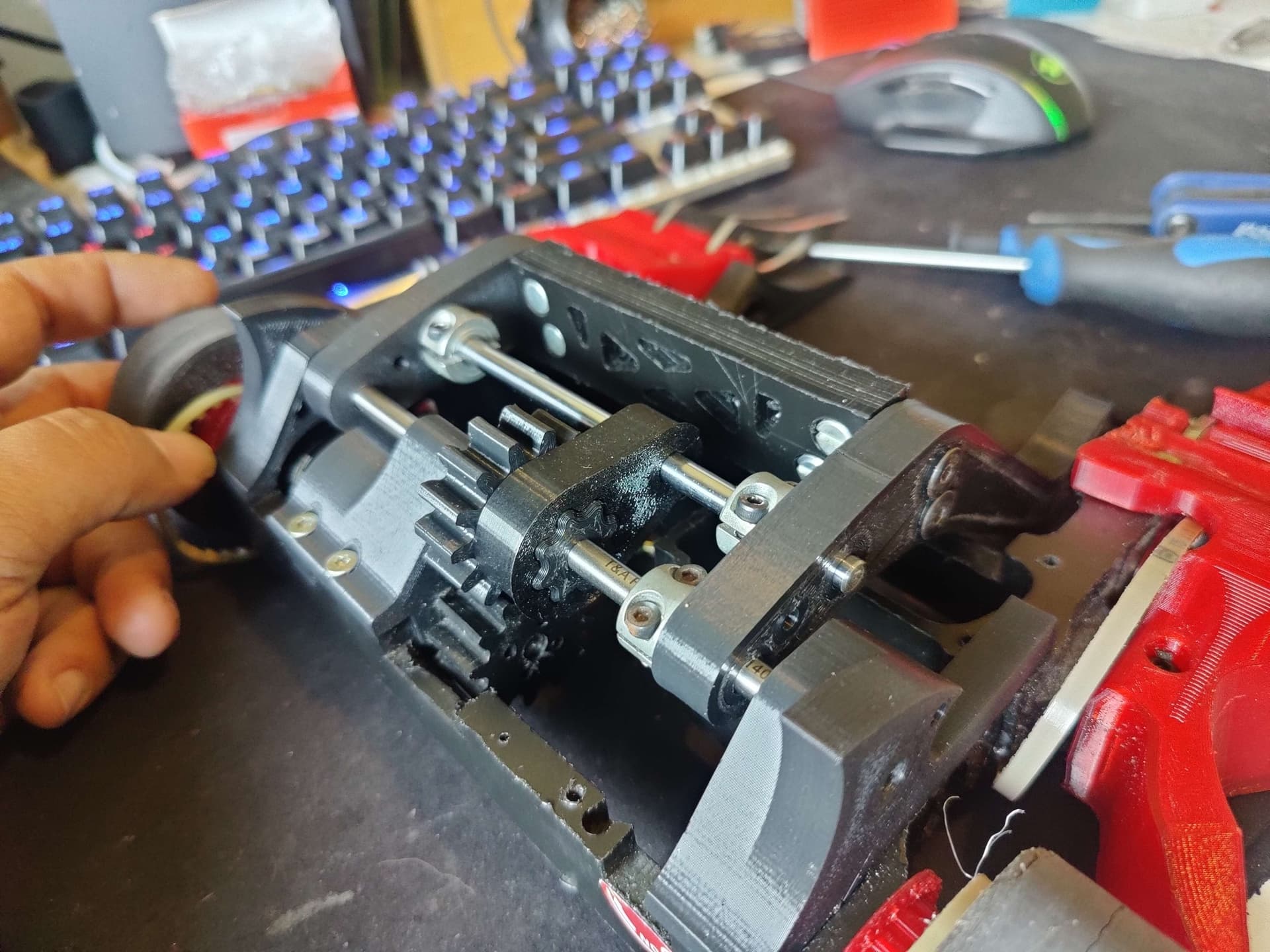
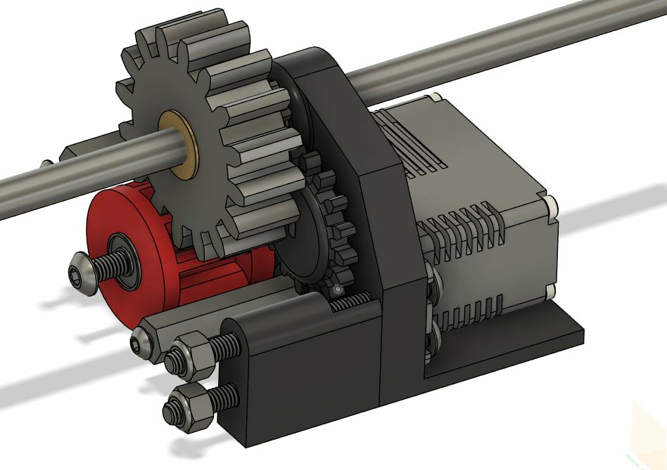
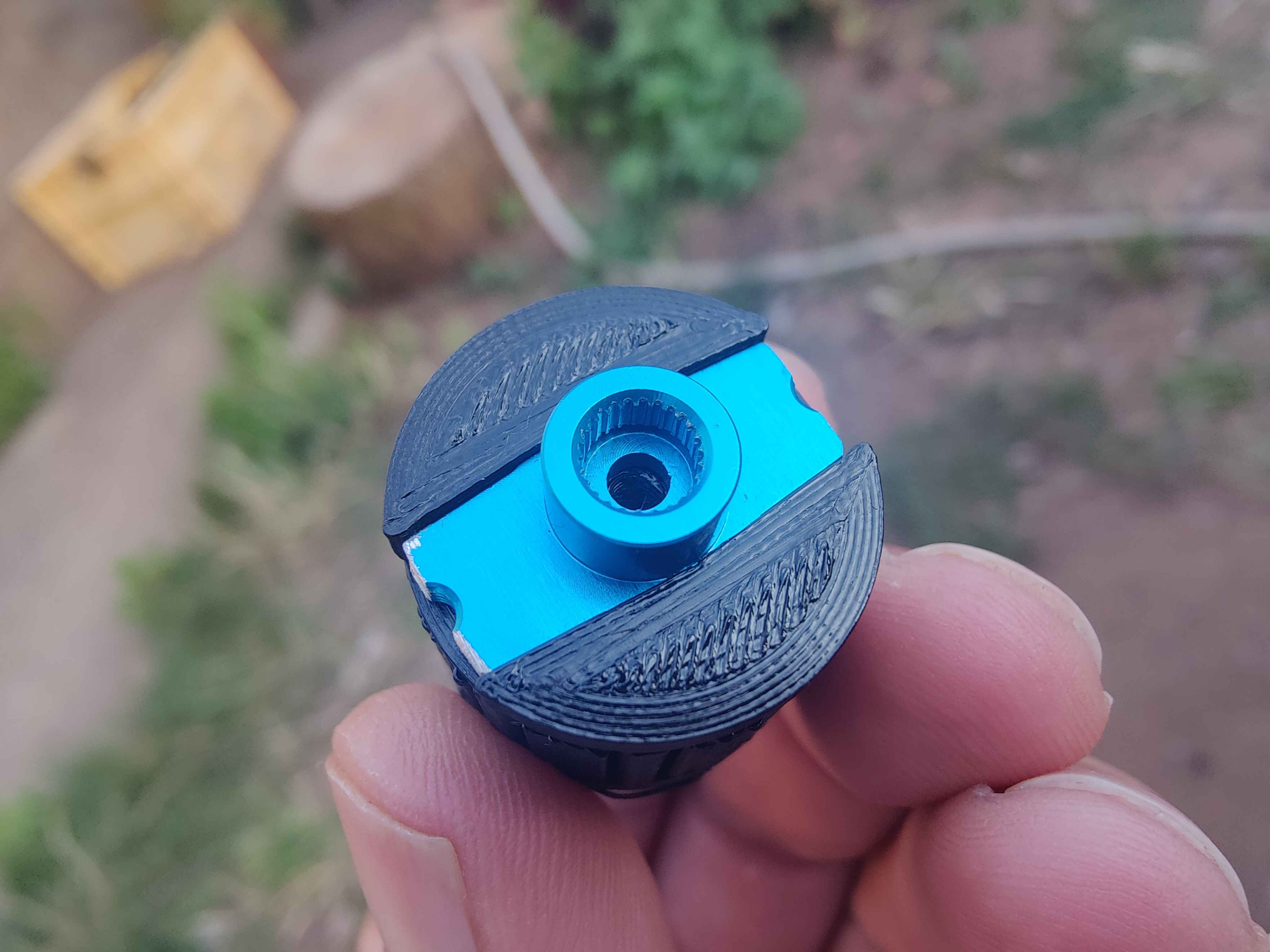
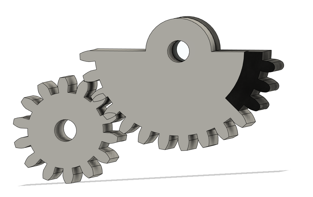
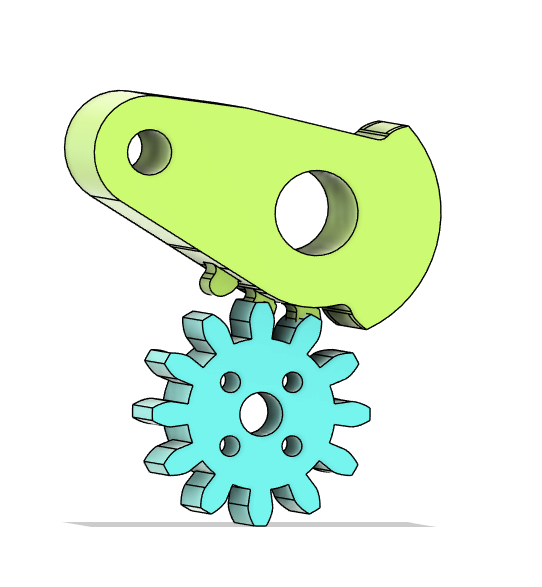
My first move was to raid my box of old printed prototype pieces for the servo and get hacking at them to see what was feasible and after a little bit of playing I decided on roughly this:


Essentially hacking off the ring gear stuff and mounting a repeat hub onto the gearmotor and a big TPU horn onto that.

Press fitting the Potentiometer into the horn would allow me to use the arduino to run endstops and cut power to the motor before hitting the end of the range of motion and stop the gear box from eating itself.

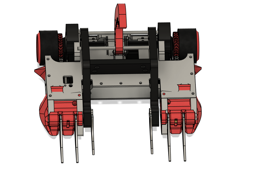
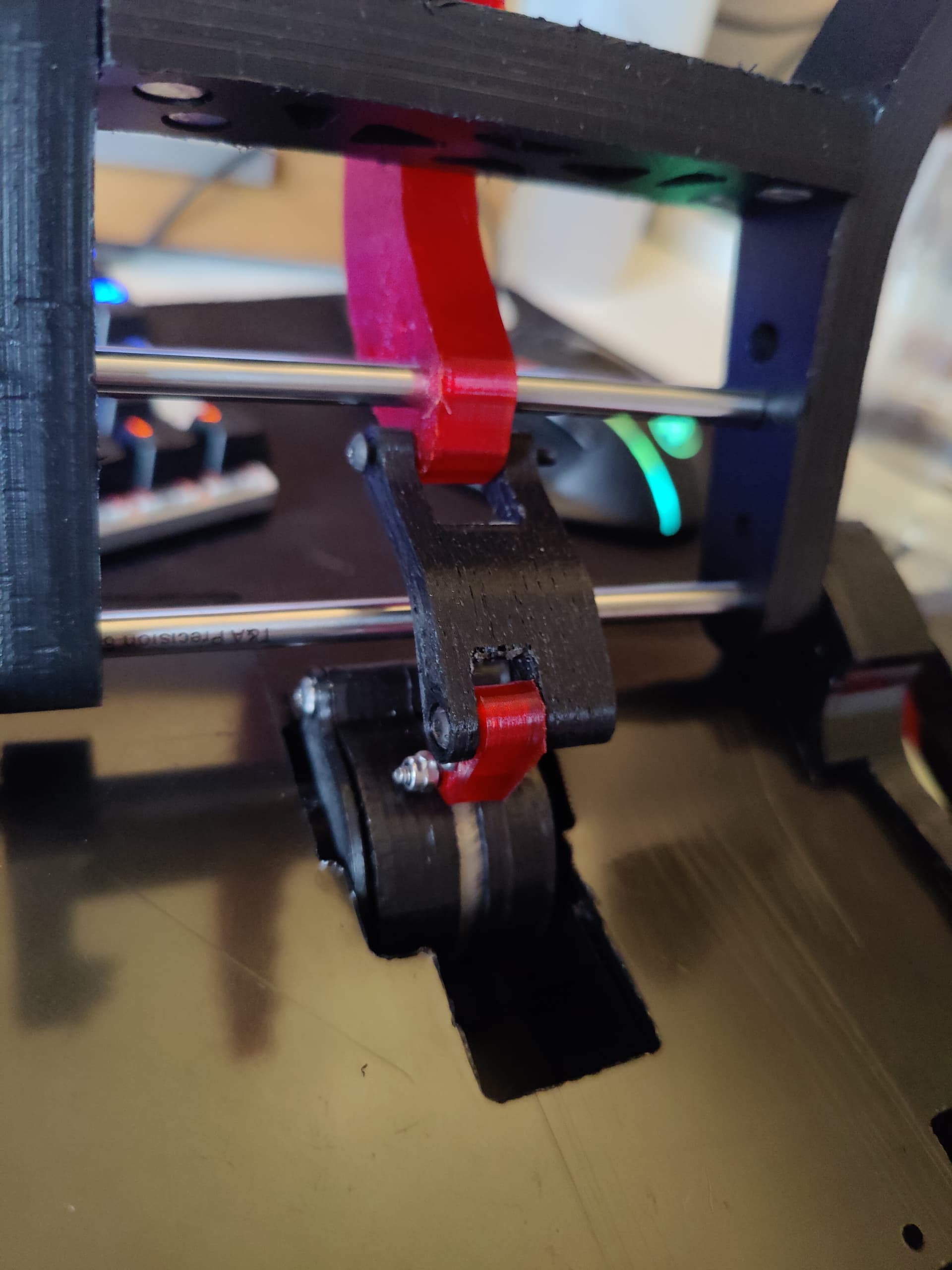
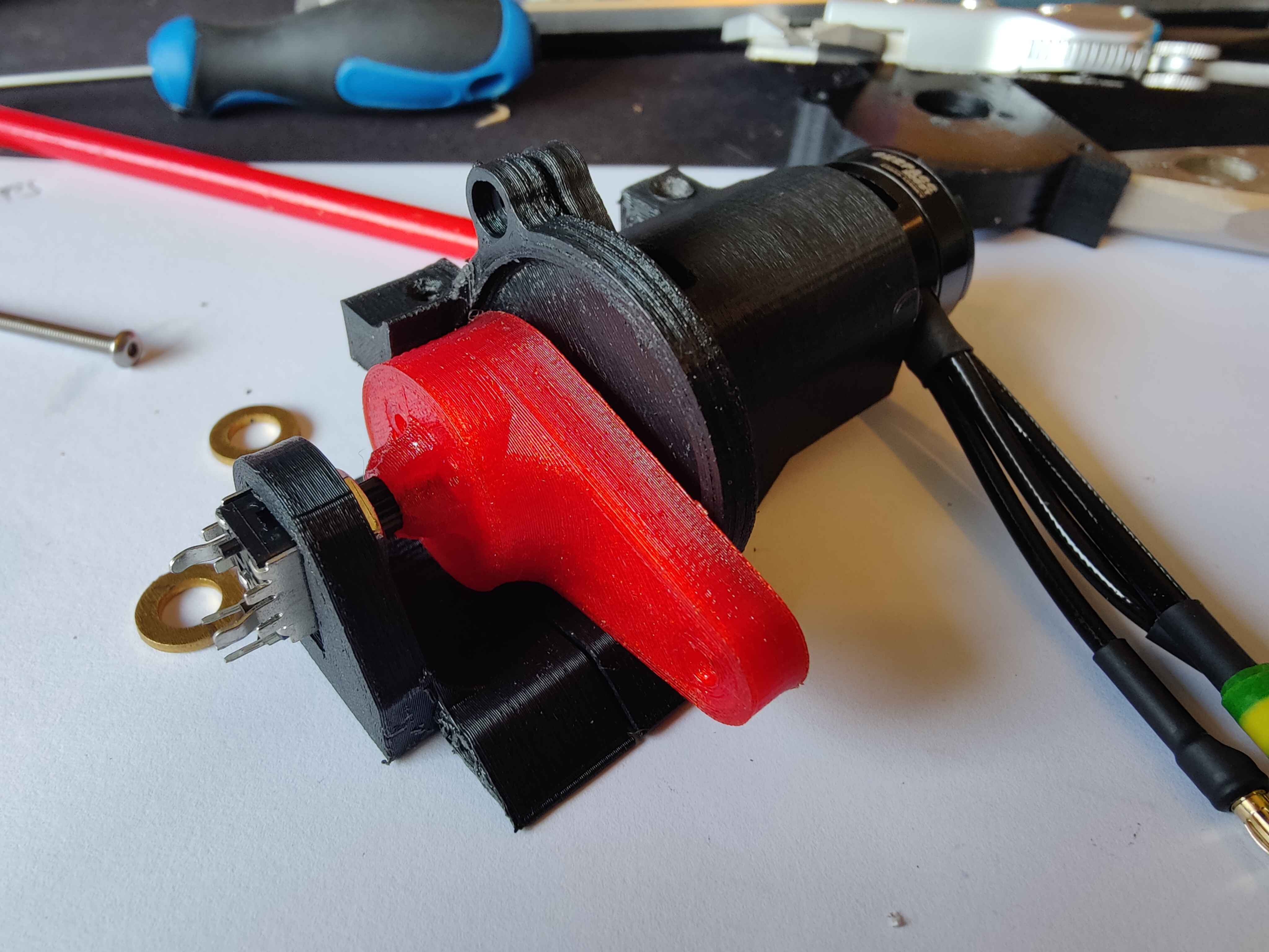
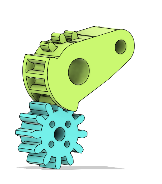
Settled on the idea a quick bit of cad and some hours on the ender later and I had this:


Basically the same thing but less hacky.

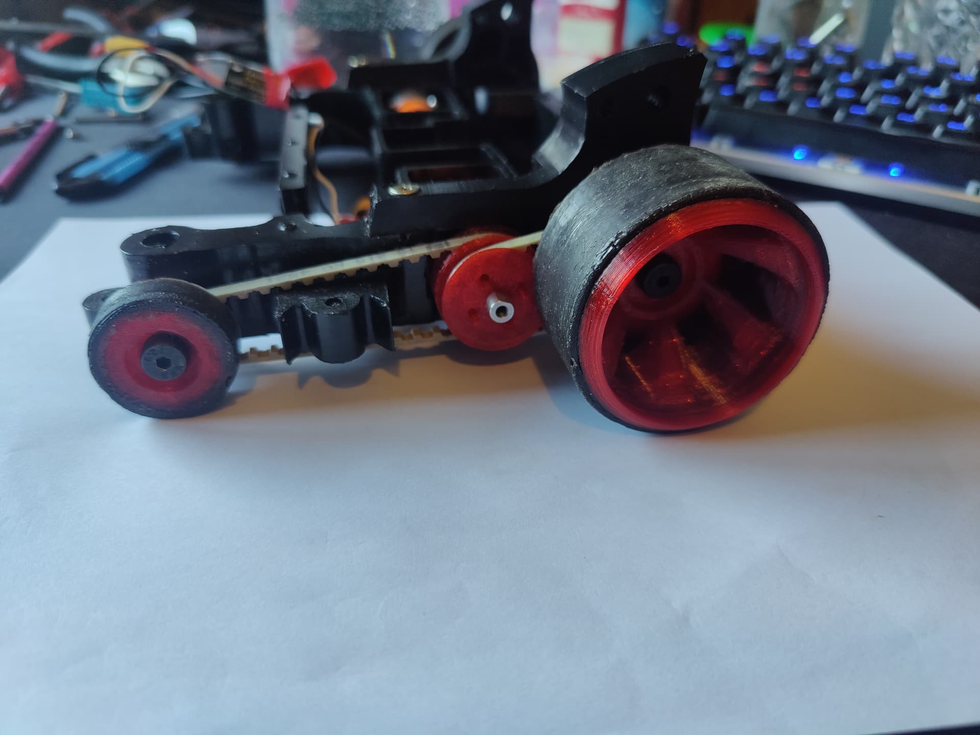
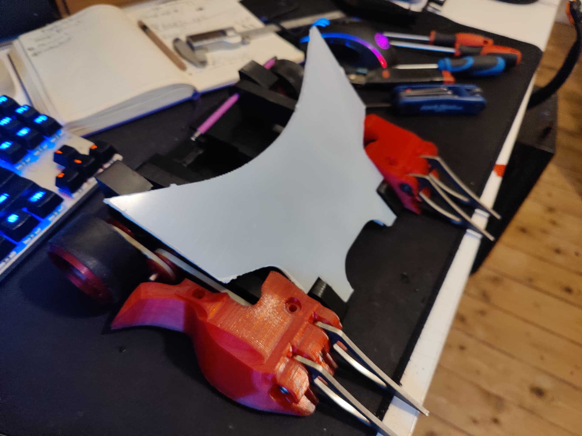
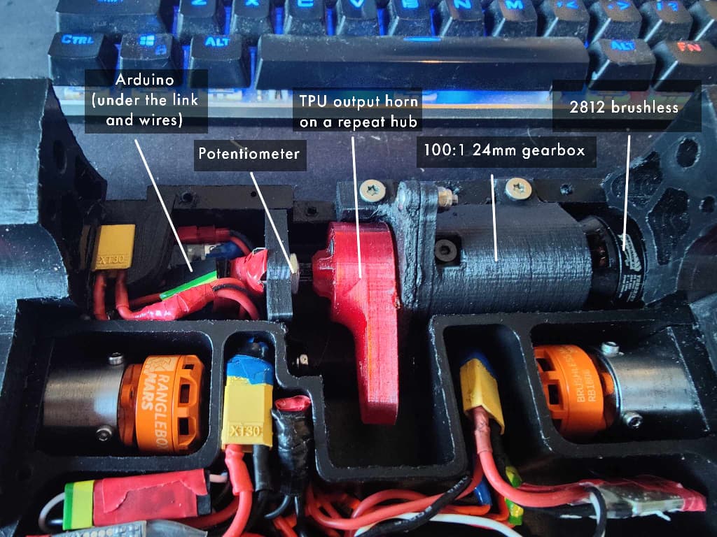
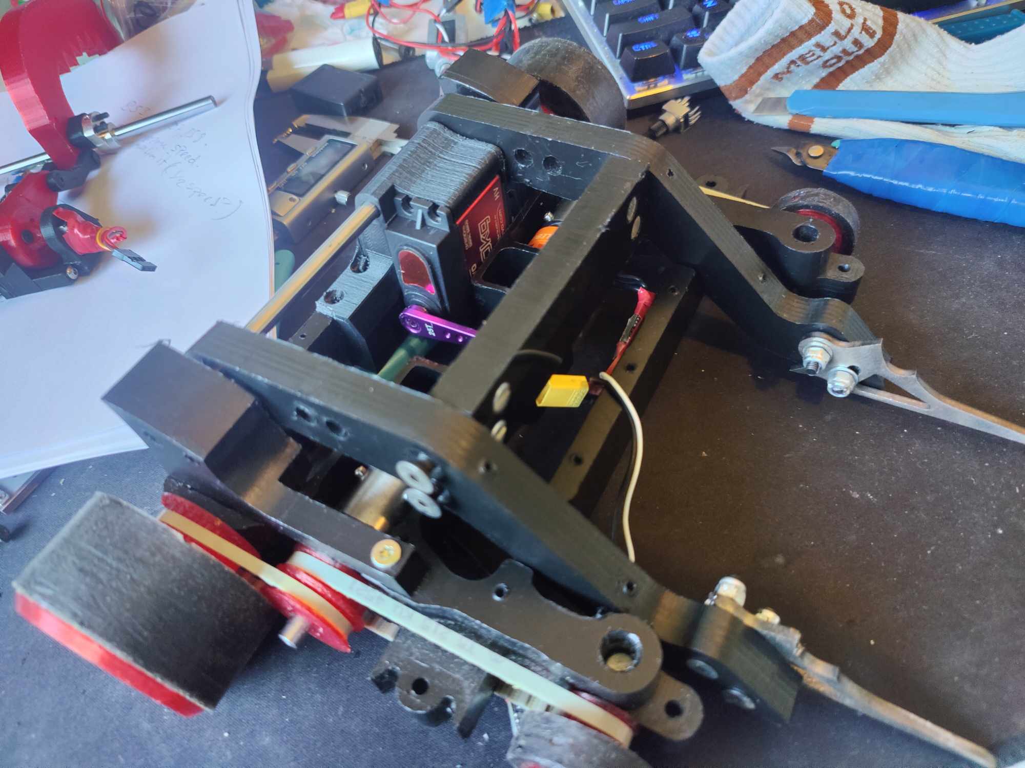
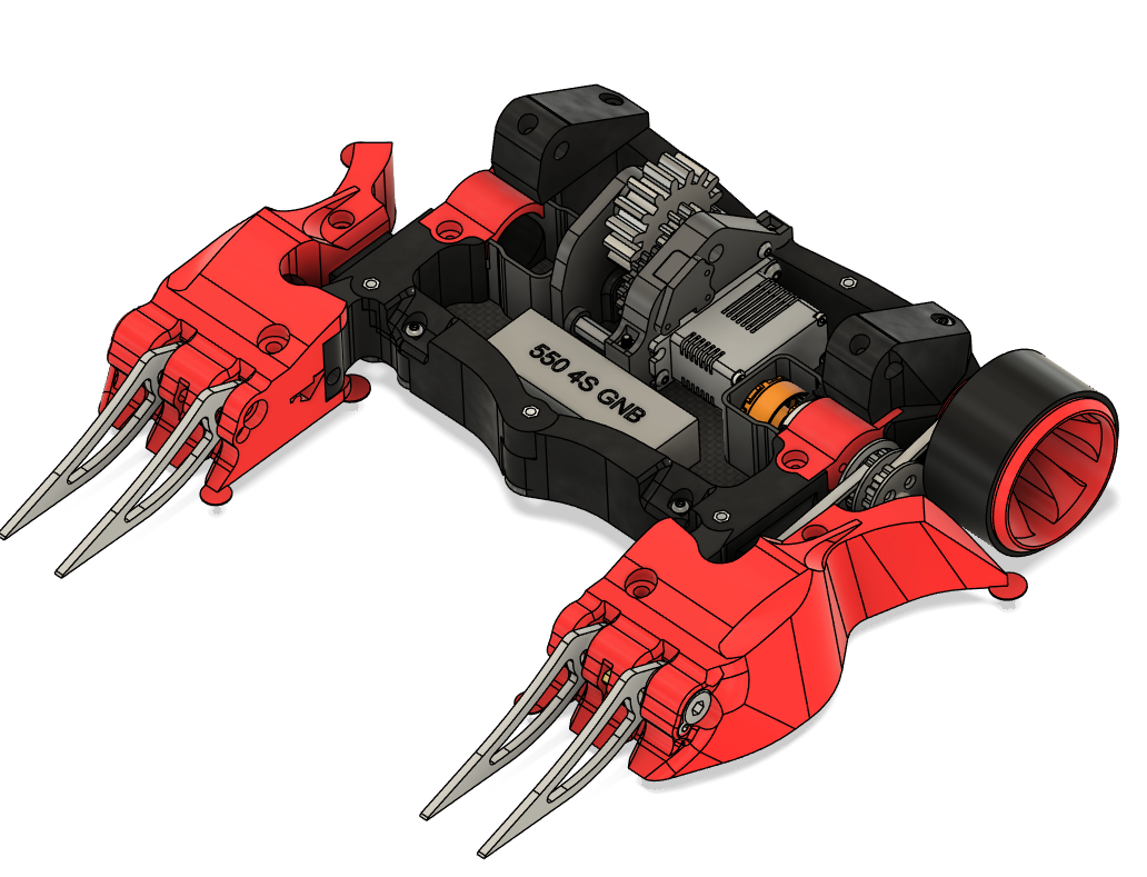
Installed into the robot and it looked like this:

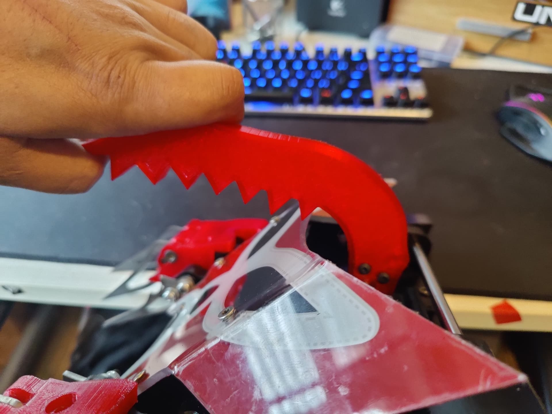
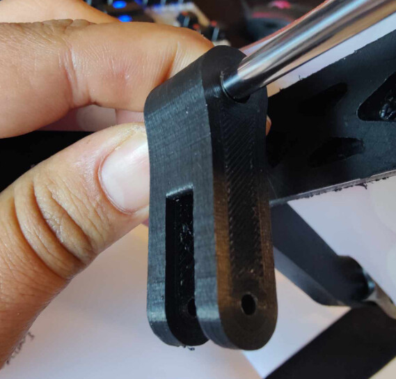
Then designed and printed a suitably chonky linkage to fit to the horn and grabber shaft- this was just printed out of PLA-ST:

In testing it seemed all good but had a real tendency to back flip when firing the weapon :rofl:

I adjusted the code on the arduino, pulling the top end stop forward a bit and adding some zones close to the end stops where it drops the power to 1/2 and then 1/4 to lessen the recoil and called that done. Flip-ador as I found myself calling it was as ready as I was gonna realistically make it and with it now being Thursday before the event - I needed to switch focus to making spares and back up plans.

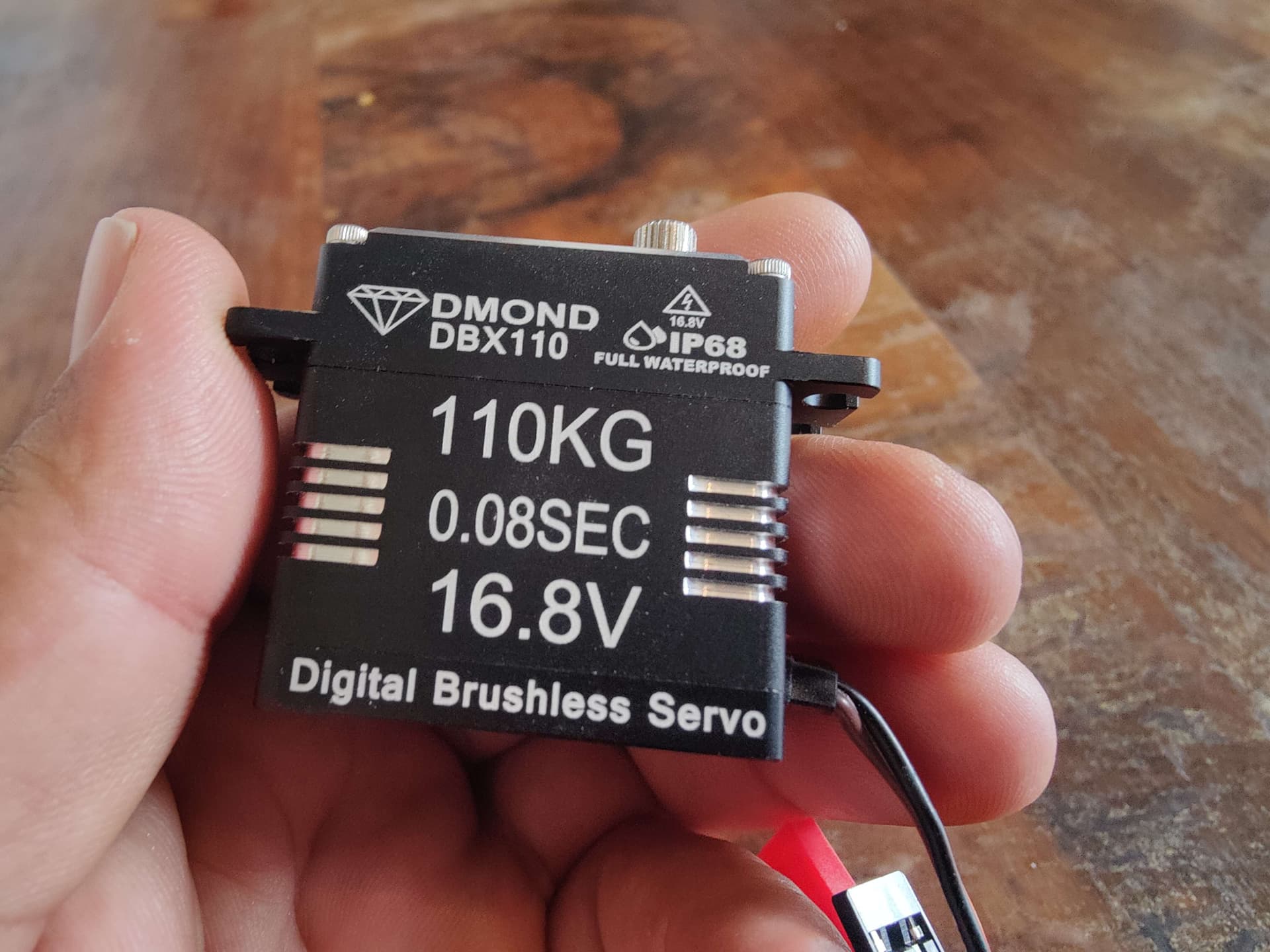
With some doubt about how well this quickly thrown together flipper weapon was gonna work I cadded up a backup backup plan - using a regular cheapo 35kg servo- which thankfully I never had to use:


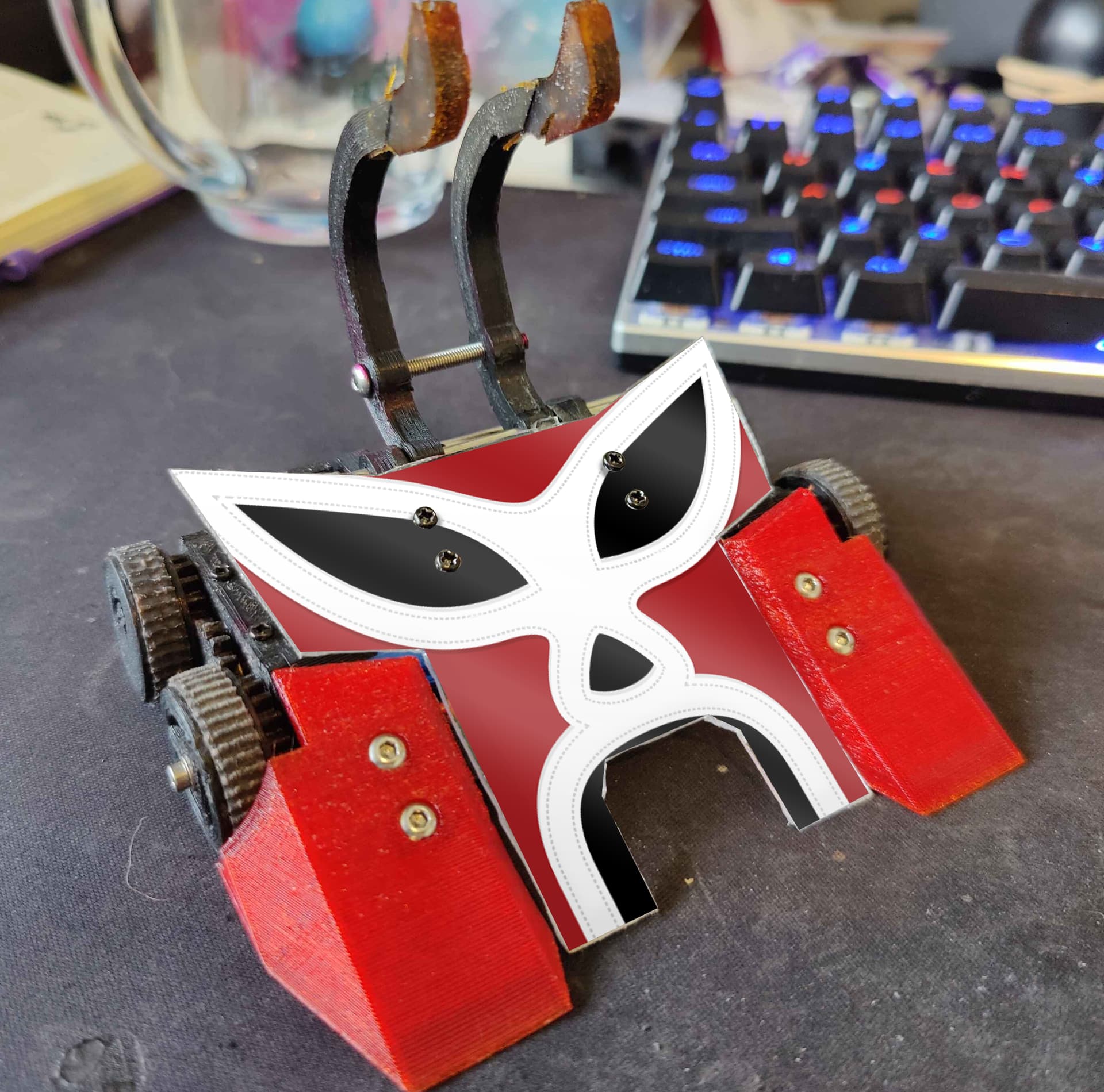
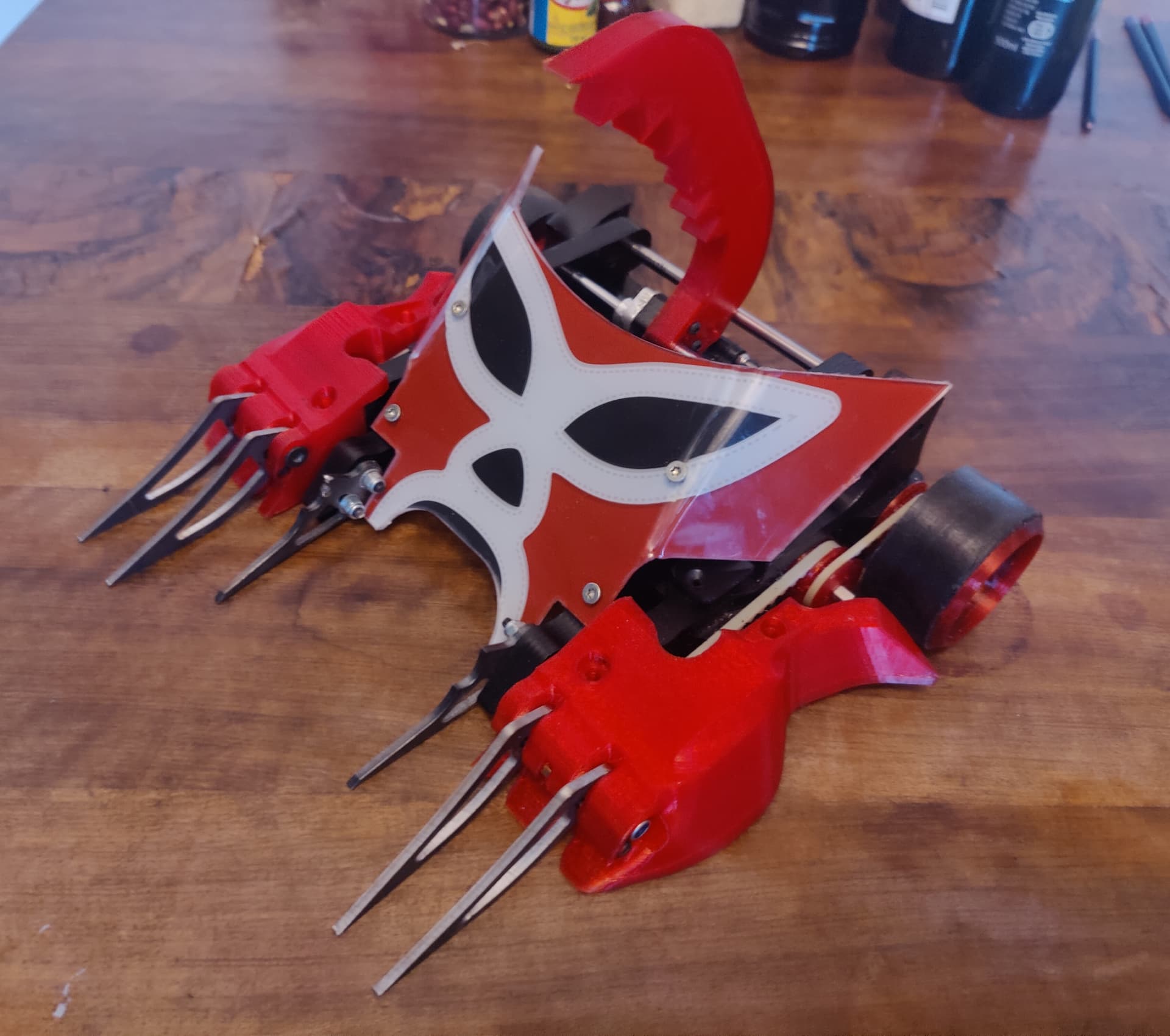
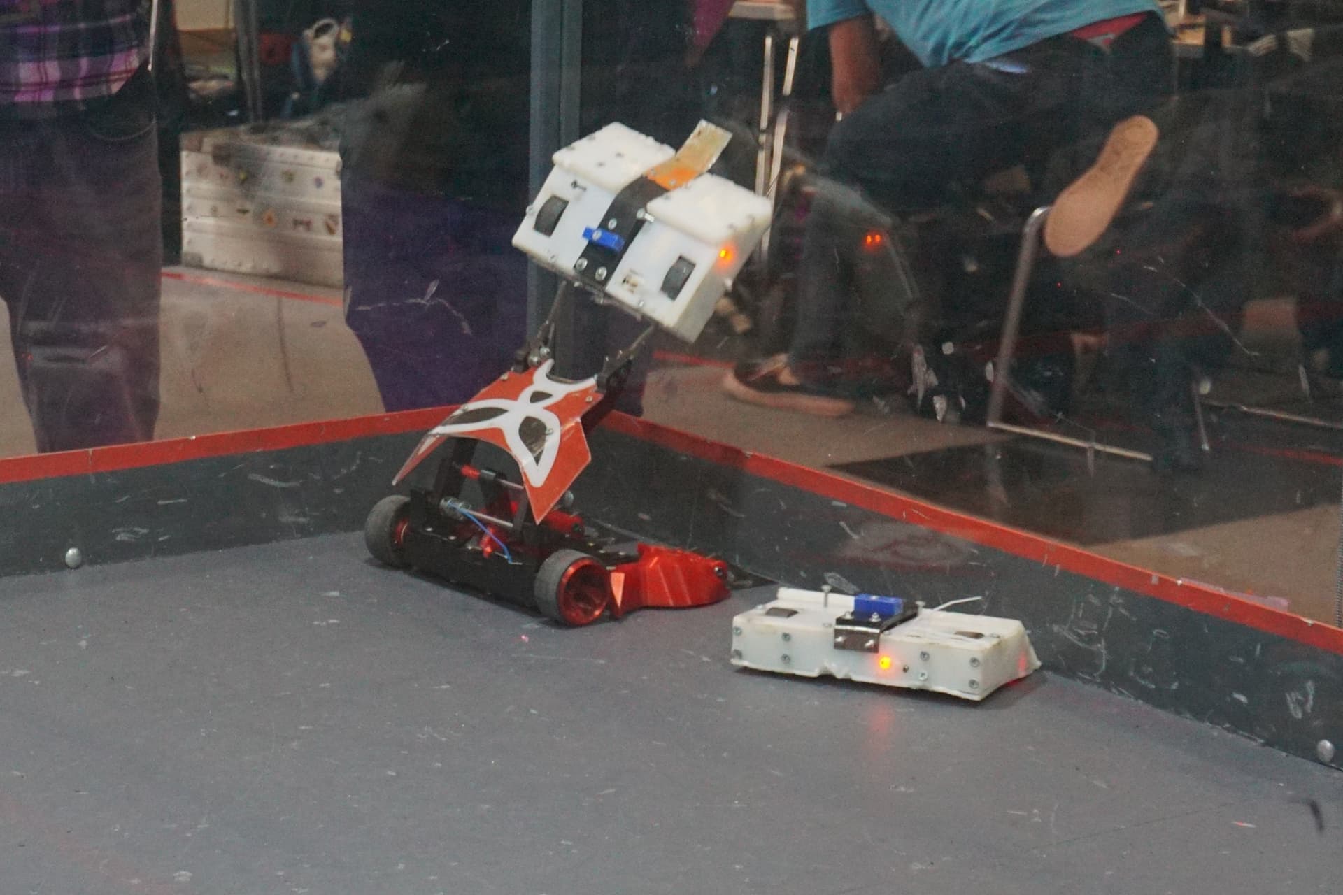
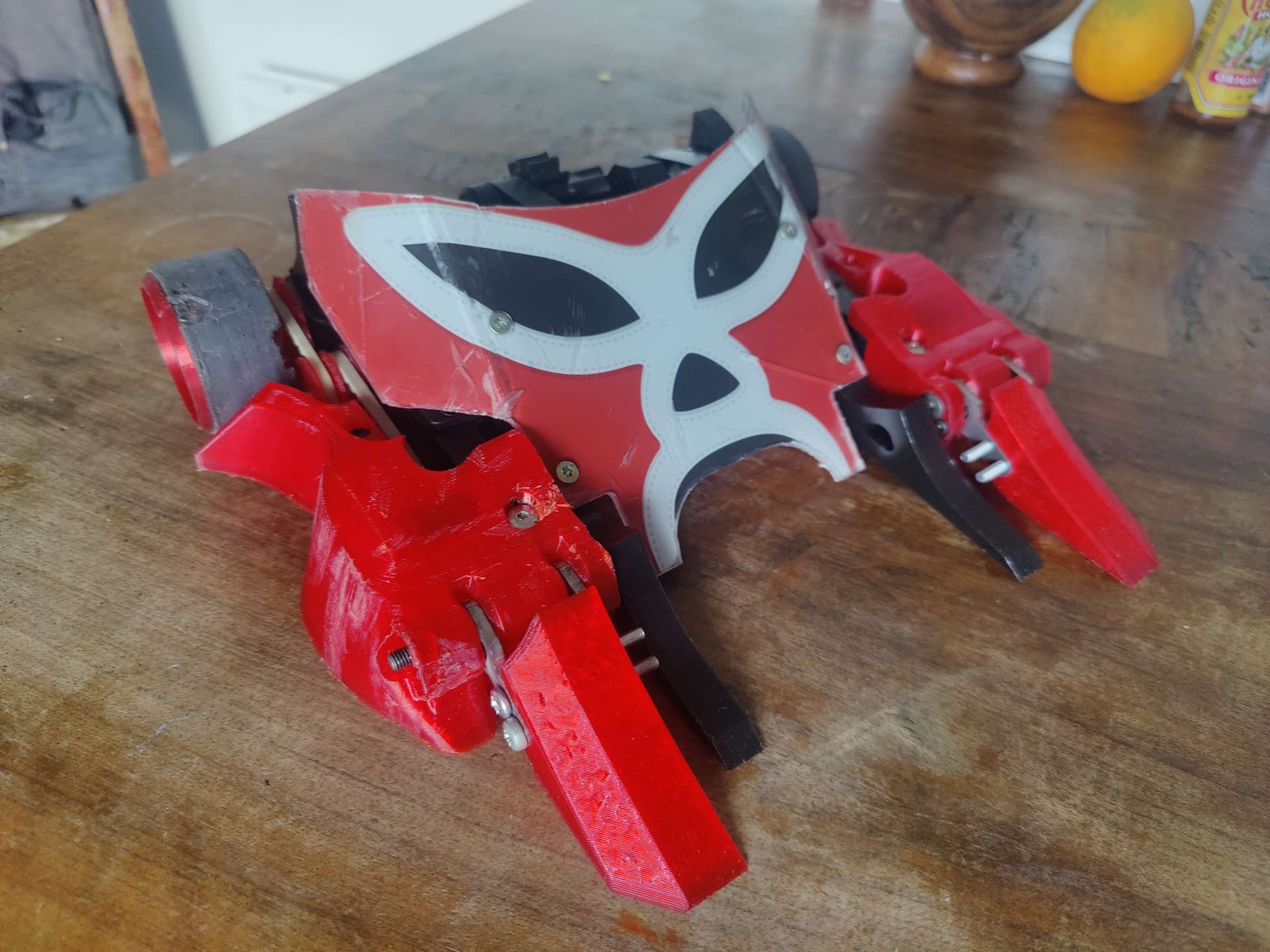
All in all Flip-Ador ended up attending Champs, getting some good flips in and making the top 8. It was a really fun bot to run on the day but absolutely not what I want Luchador to be.

However, it was so fun to run that I think I might spin it out into its own thing, give it its own mask design and run it under my old feather’s name: Mucha Lucha
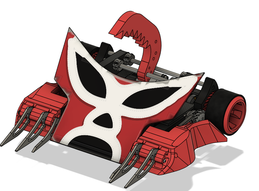
While Luchador will return at some point soon and will once again be Grab and Lift

6 Likes

It’s fab to see how much work you put into designing and perfecting this, even when it doesn’t go right. Really shows what’s needed to do well!

1 Like

Thanks.

It’s easy to write about the wins. I find it much harder to find motivation to write about the struggles and rocky development of when things don’t go as planned - but I also think that has just as much value so really wanted to get the whole saga in the build log :sweat_smile:

Absolutely great read this Jack!
The boldness to build your own super heavy duty servo because one doesn’t exist is so within the spirt of the hobby and one of the reason I enjoy it so much.

The fact it hasn’t worked first time around will just make it so much more enjoyable when you eventually nail it.

1 Like

Thanks James, I’m not exactly 100% sure what’s next for the mega servo project. - I know it needs to be more robust and to have even more torque (at least at lower RPMS) so it’s back to the drawing board a bit! - as a project it’s really stretching my skillset which is fun.

Bigger lower KV motor? Brushed? Sensors? Who knows right now - but am keen to work on it further in the future.

So I decided to run flipper Luchador at BBB pub beetles. Figuring that all the extra electrical complexity of an Arduino is a bit wasted only running end stops I decided to instead to let the motor over drive but look at some form of mechanical clutch to soften the blows on the gearbox instead.

I decided to try and utilize the flex of TPU to achieve this - using a rounded splined interface from a gear into a tpu linkage. The intension being that the outer TPU part would deform and stretch under heavy loads and allow the interface to skip

The clutch point/torque it takes to do so could then be adjusted by varying the number of walls on the TPU print and the amount of tolerance on the fit.

This approach came together relatively quickly in prototyping and seemed to work well in testing.

I also needed to make a front end set up that was legal for the pub beetle rules modifiers (,no metal forks essentially) and settled on this

Hinged TPU wedglets to replace the passive forks I hoped would work similarly to my usual forks while replicating my usual lifter tip shape directly into the hdpe arms I felt sure would be fine as they’re recessed compared to the passive front end anyway.

On the day the bot performed excellently - right until it didn’t. In the semi finals against flick my weapon broke and got stuck in the up position (a nightmare scenario really). With some tense driving I managed to secure the win despite this - but on returning to the pits and stripping the weapon gearbox down I found this:

I guess that clutch just wasn’t clutching easy enough for the 24mm gearboxes tastes :joy:

Without the spares to get it up and running I bowed out of the final - so flick and grab crab went in for a pseudo final for the audiences benefit.

Not the end I wanted but otherwise an awesome day and event.

2 Likes

Luchador is returning for champs. Having ran flipador a few times now - I really wanted to return to the full grab and lift roots.

I got pretty distracted this year building boomslang so have done far less r&d on the mega servo project than I had originally hoped - so I decided to look at something a bit more achievable in the run up to champs.

Dmond released a 110kg 16v servo and this piqued my interest. I’m still not convinced that any 1/10th scale servo can really survive the kinda abuse that hard linked beetle grab and lift throws at them… but what if I could reduce this abuse and do more to protect the servo?

With this approach in mind I went ahead and ordered one and stripped it down as soon as it arrived to see what I was dealing with…

Pretty much straight away I was skeptical of the gear box. It’s got that bright shine to it that makes me sure it’s stainless for starters, but also a number of interim stages are a bit weedier than I’d like.

Speed seemed reasonable but range of motion was pretty much bang on 90 degrees. This was likely to be an issue with me trying to actuate a grabber and a lifter with it and I don’t really want to gear it up and loose torque while also multiplying the forces that gearbox comes under…

Delving deeper the motor and control board looked good. A 17-18mm brushless inrunner with sensors mounted to a control board and using a simple pot for positional feedback.

In fact this set up was looking incredibly familiar. It’s almost identical to the guts of the Holmes hobbies servo I ran at the end of mk3. Digging out the Holmes hobbies corpse from my spares box confined it - they even had matching pinions on the motors.

So a bit of fiddly fucking around later and the new Dmond internals were up and running in the holmes hobbies case/gearbox. The hh one is really nice, with hardened steel gears and I already have a spare geartrain for it. I haven’t bothered to work out the respective changes in reduction between the two gear boxes - that’d be some boring nerd shit (obviously I am in fact a massive nerd - I’m just a lazy one) - we’ll see how torque works out in testing.

Next I started to think about how to protect the servo from munching itself. Accumulative shock loads had killed the HH one - with the wee motor shaft eventually slipping in the tiny brushless inrunner - and I want to avoid that fate here.

After a bit of thinking and some messing about in cad I got to this. The red gear is a TPU gear with flanges to prevent the teeth folding - I’m hoping this should eat up some shocks. It’s mounted to a recessed servo horn on the servibsideand has a bearing for double support on the other side.

This drives the main lifter gear (grey) that’ll run the grab and lift. There is a bit of reduction here to lower the forces on the servo too. This lifter gear is actually a duplex gear with a much smaller secondary gear on the other side which drives the pot gear (black).

I’ve pulled the pot out of the servo and mounted it externally and it’s actuated by this pot gear. This means that the servo control board is tracking the position of this gear and not the servo horn. So I can adjust my range of motion independently from my output rpm but adjusting the gear ratio between the output (lifter) gear and the pot gear :grin:

A bit more development later and it started looking more like this:

Pretty happy with this approach I decided to try and integrate it into the robot…

2 Likes

So next up I dropped the servobox into the Luchador mk4 cad and…Discovered that it was too wide to fit between the drive motors while also being too deep to slot behind them… Fuck!

Naturally I did the obvious and sensible thing and decided to… completely redesign my chassis to accommodate! Yay! :laughing:

I couldn’t really be arsed to make another billet so decided to pivot to CF/TPU + stand off build like I did on boomslang.

So off I went to cad to completely redesign my chassis and build style of the bot. After more hours than I’d really like to admit I had this, same same but different:

Designed around boomslangs baseplate to avoid having to buy more CF meant I was having to work around boomslangs stand off positioning, but it was coming together slowly.

It was around this point that I realised I was an absolute idiot and completely redesigning my robot because the servo box was 4-5mm too wide was fukin dumb and that really I ought to just tweak the servo design to be marginally slimmer :rofl:

So I did just that and integrating the revised servo box into the existing robot was suddenly very straight forward and after a little adaptation of the lifter/grabber mechanism I ended up with this:

With that sorted I could start making the changes and get onto grab and lift testing :grin:

2 Likes

At this point the build came together pretty fast. I had to make some minor alterations to the existing chassis but it was all very simple and allowed me to get testing asap.

These early tests were promising but too slow for my tastes so I got to rejigging the gearing ratios on the servoboxs external stages.

Increasing the tooth count on the tpu servo gear and dropping the tooth count on both the lifter gear and the grabber gear sped it up a bunch.

However now with the increased load on the tpu servo gear under particularly big/awkward lifts the servo gear would skip. Not at the teeth but at the keying between it’s recessed horn and the print itself.

A quick trip to eBay and a few days wait had me with a double horn which did the trick - spreading those forces across two edges/faces rather than one which seemed to do the trick

Through out this process I had made sure to keep the shaft positioning on the lifter the same this would let me still run the flipador set up. Being able to switch between grab and lift and flipper configs was an exciting prospect so I figured the next thing was to revisit the flipper config…

9 Likes

Returning my attention to the flipper weapon and the absolute pasting that the gearbox took at BBB pub beetles I initially tried iterating on the TPU splined clutch. Playing around with different wavey spline profiles, reducing the amplitude of the splines to lower the torque it would clutch at.

After about 4 or 5 iterations that were all either far too easily clutching or suspiciously difficult to slip - I came to the conclusion that while this approach does work - it’s far to annoying and labour intensive to dial in.

So decided to pivot to a traditional friction clutch. The design for this came together pretty easily and quickly - it isa pretty traditional approach that’s seen a lot of use at feather etc.

The first draft was designed around a custom bored out M10 bolt, bored out to slip fit on my usual 6mm steel lifter shafts. However the realisation that M12 hollow bolts have a 6mm slip fit on the bore off the shelf and I have tons of weight free made me go with that to cut out the lathe work (path of least resistance + me being lazy)

It’s pretty standard affair really, from right to left:

  • M12 hollow bolts is the base of it all
  • HDPE gear mates to the motor gear
  • Cork friction pad
  • Pla splined insert to apply pressure to the cork pad (because I wanted the linkage to be TPU but didn’t want the tpus squish to make the pressure unreliable)
  • TPU linkage to transmit torque into the lifter and provide a bit of cushion
  • Thrust washer to isolate the nut from rotational forces
  • Locknut to apply lateral pressure to the stack

This I thought would streamline things, now adjusting the slip point would be as simple as turning a nut :nut_and_bolt:

I knew this was going to be a pretty heavy set up - there is a reason you don’t generally see M12 hardware at beetle scale and I was not wrong

So off I went to testing and initial results looked promising. However after a few more flips the slip point started to ease off and the clutch started slipping at lower torques.

On investigation it looked like the cork was compressing and the stack loosing tension as it became fractionally narrower. I hoped this was just it settling in and was just a sort of “bedding in” phase so I readjusted and kept testing until…

The cork friction pad just gave up entirely.

A bit tilted at this development in my fancy and frankly absurdly heavy clutch I did the entirely rational thing and decided to scrap the approach entirely!

Regular readers might be noticing a pattern in my behaviour/decision making here! :rofl:

But jokes aside I was coming to the conclusion that the ven diagram of “how much torque it takes to do the flips I want” and “how much torque it takes to break my own robot” was just a fukin circle! :new_moon_face:

Long term a new approach was needed! - something that would clutch super easily - but only at the end point. In the run up to champs however I decided to simply revert to the tpu spline set up. It worked for 5 fights at pub and as an optional config that’s be more than enough to see me through champs and I didn’t want to waste more time/effort/bandwidth when I had plenty of other things to sort pre event.

2 Likes

So Martin knows me well enough to predict my utter inability to leave things alone… and he was right :rofl:

After seeing Ioan’s new flipper set up on cascade and his partial gear TPU compression spring end stop to allow the lifter to rotate enough to disengage the gear but spring back into mesh once torque drops off it got me thinking.

I’ve experimented with self clutching TPU gears in the past playing around with rounded teeth profiles and relief cut outs to encourage teeth folding and skipping and have used this approach successfully on an axe/hammer project.

However TPU gears tend to be trash at high torque applications. Unreliable at transfering high torque loads and have a tendency to permanently deform under strangbox levels of speed and torque combined.

One idea id played with in the past was a 2 part gear with normal HDPE gear for most of it but a TPU section with rounded teeth for the end. However I never pursued it as I didn’t think the join would last under those kinda loads.

This time around with a bit more experience of high reduction brushless and better understanding of how gear materials react to this conditions I revisited the idea for a TPU gear and ended up with this

Which I am affectionately dubbing the: “Reptar Gear”.

Big chonky gear teeth with flanges on each side of the flip portion of the motion - and much much smaller teeth for the end of range of motion. These smaller gears have rounded profiles on the up motion side them and small relief cut outs on the opposite base. This biases them to flex very easily in the up direction but not in the down direction acting like a pawl.

The logic here being that if I can make them fold and skip easy enough I can make sure that they do not encounter enough torque to do any destructive deformation.

This makes for a pleasingly simple flipper mechanism

After some substantial stress testing this looks really promising. I went through about 2/3rd of a lipo charge doing continuous flipping of a 1.6kg weight before the gear started to fail.

And when it did start to fail it was the main flipper tooth splitting at the layers. At this point it would still manage small flips and self rights but would skip on big awkward flips - so a pretty graceful failure mode. It also took what I would estimate to be 2+ events worth of flips to reach this point and the pawl teeth show no signs of wear.

So this is a huge win - a great result. A set up that skips at the end of motion with very little torque, while still providing big flips. That is easy to print and a trivial job to swap and that seems to have a life span of over an event.

I am very excited to see how it goes in practice

6 Likes

Outstanding work on show here.

Nobody does R&D like you, props for the perfect balance of detailed documentation, theory and anger. Expecting a podium finish for this guy.

1 Like

Thanks Harry means a lot coming from you - your bots are always wonderfully technical.

As for the R&D I’m just determined to crack the grab and lift problem. It’s a pretty tricky one and I very much want to have my cake and to eat it. I want it fast, torquey, durable and I want positional control - so it is quite a tall order really. - I’ll get there eventually :rofl:

Honestly I’m not entirely sold on my servo solution long term. It’s not quite as fast as I’d like and not quite as torquey as I want either. Both are close tho.

As for the anger as you describe it :rofl: - when I decided to start my build logs I made the decision that I wanted them to be an honest reflection of my actual experience of building, iterating and working on my robot, warts and all.

It’s very easy to talk about your wins and only post the positives of your robot and paint some idealised Instagram ready picture of things - but I wanted to be open about the trials and tribulations of it all - including the failures. I think that has value, I want any new builders who read this and who might be struggling to know that I struggle too sometimes and that persistence is part of the path to an effective robot.

2 Likes