Do you ever get one of those silly ideas that lodges itself sideways in your brain, filling up all available space and not shutting up until you see if it works? I am thankful that for me it’s usually just pun-based memes, but sometimes I take it a (few) step(s) too far. This is one of those times.
First up, we’re still on the bad movie train and the name comes from the Z movie that got me into Z movies, The Ultimate Ninja. Written and directed by Hong Kong martial arts legend* Godfrey Ho, filmed guerilla-style in public parks and forests by a crew mainly made up of Hong Kong Triad members (allegedly). Don’t ask me what the plot is, I’ve seen it a dozen times and still can’t follow it.
*they made him a professor of film-making at a local university for his pioneering “cut and splice” techniques**
**which was mostly just him stealing footage and music from foreign media and roughly splicing it together with his own footage with no regard for things like “aspect ratio” or “audio levels”.

Back to robots. There’s no way I wasn’t going to make my first spinner extremely weird, and I tried to combine two dumb ideas into one bot; can I spin the weapon motor in opposition to the weapon for some gyro cancellation, and exactly how far can I take the “PCBs as frame rails” concept in my quest to make my robots as obnoxiously small and tightly integrated as I can, often to my own detriment in the arena?

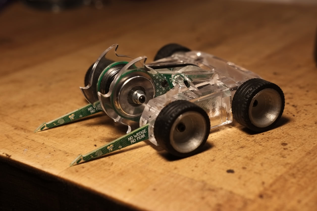
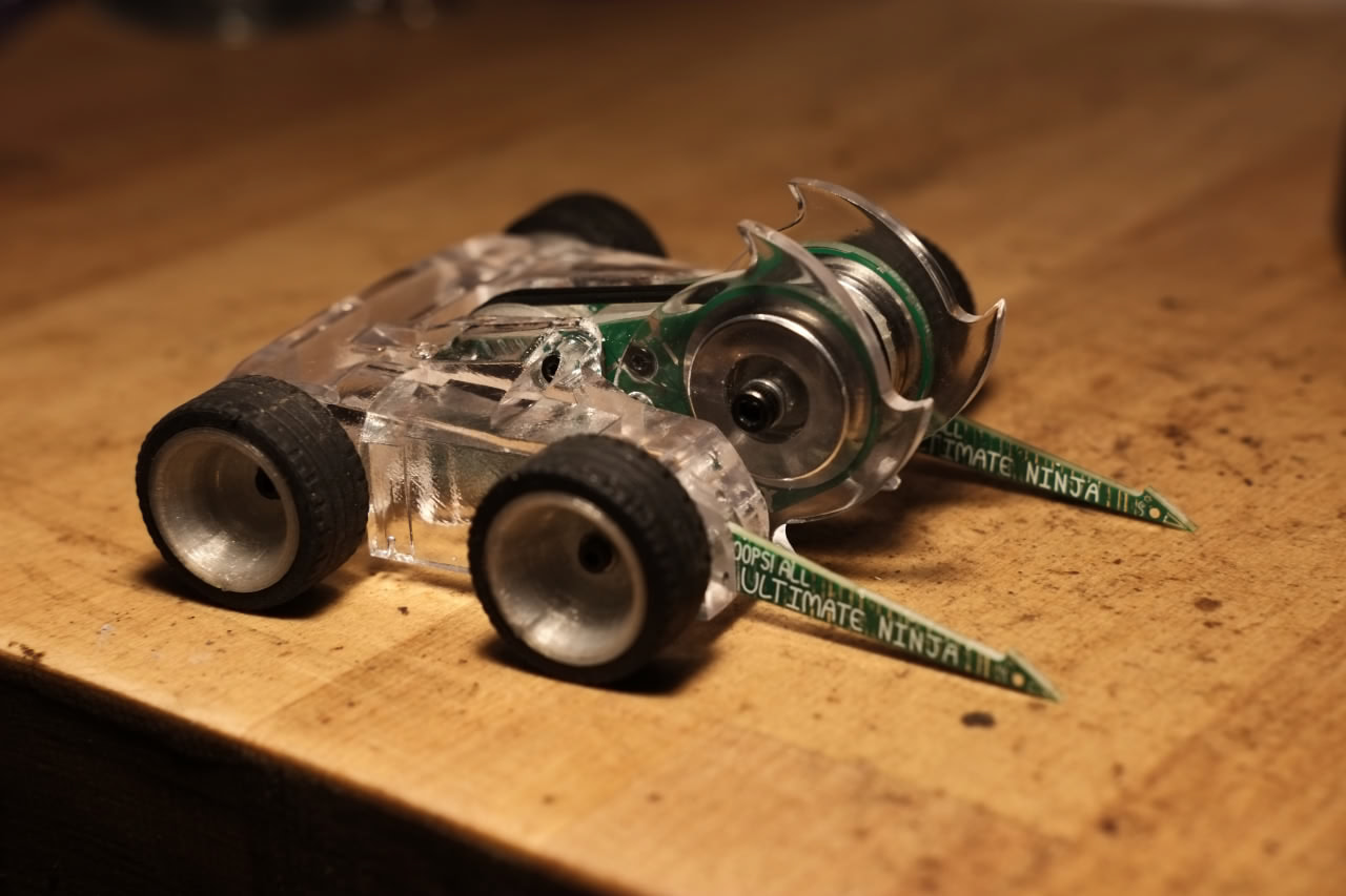
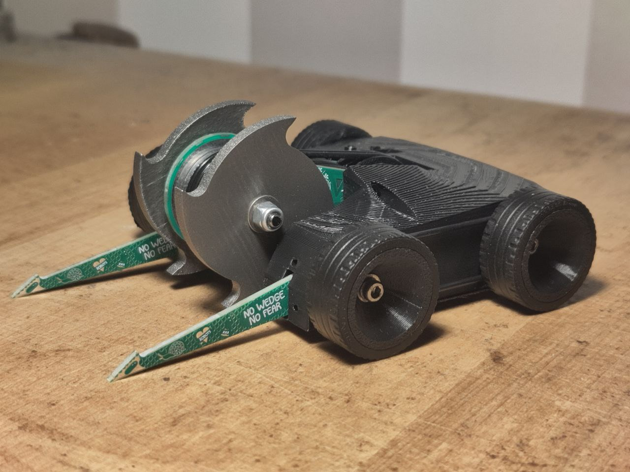
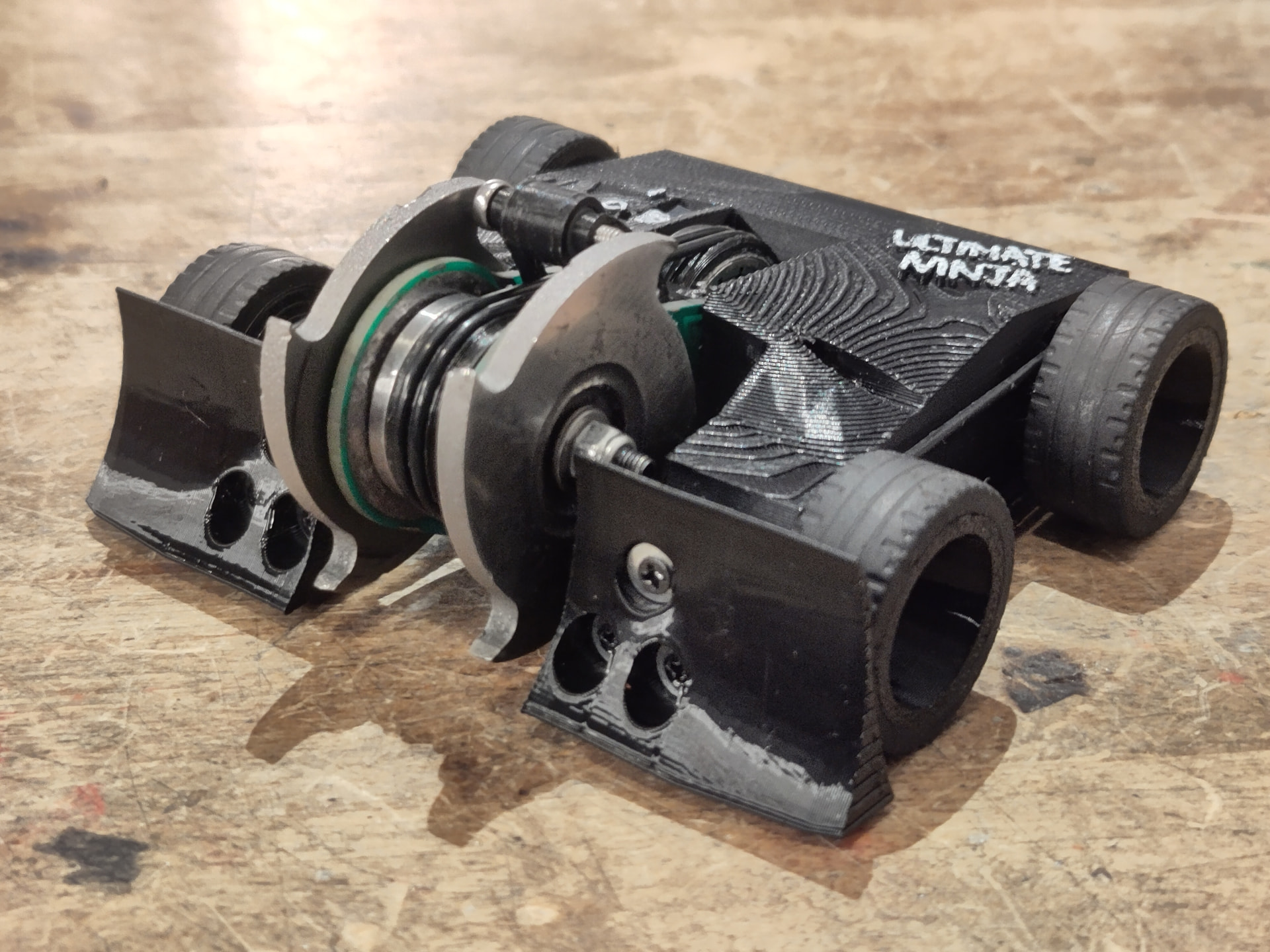
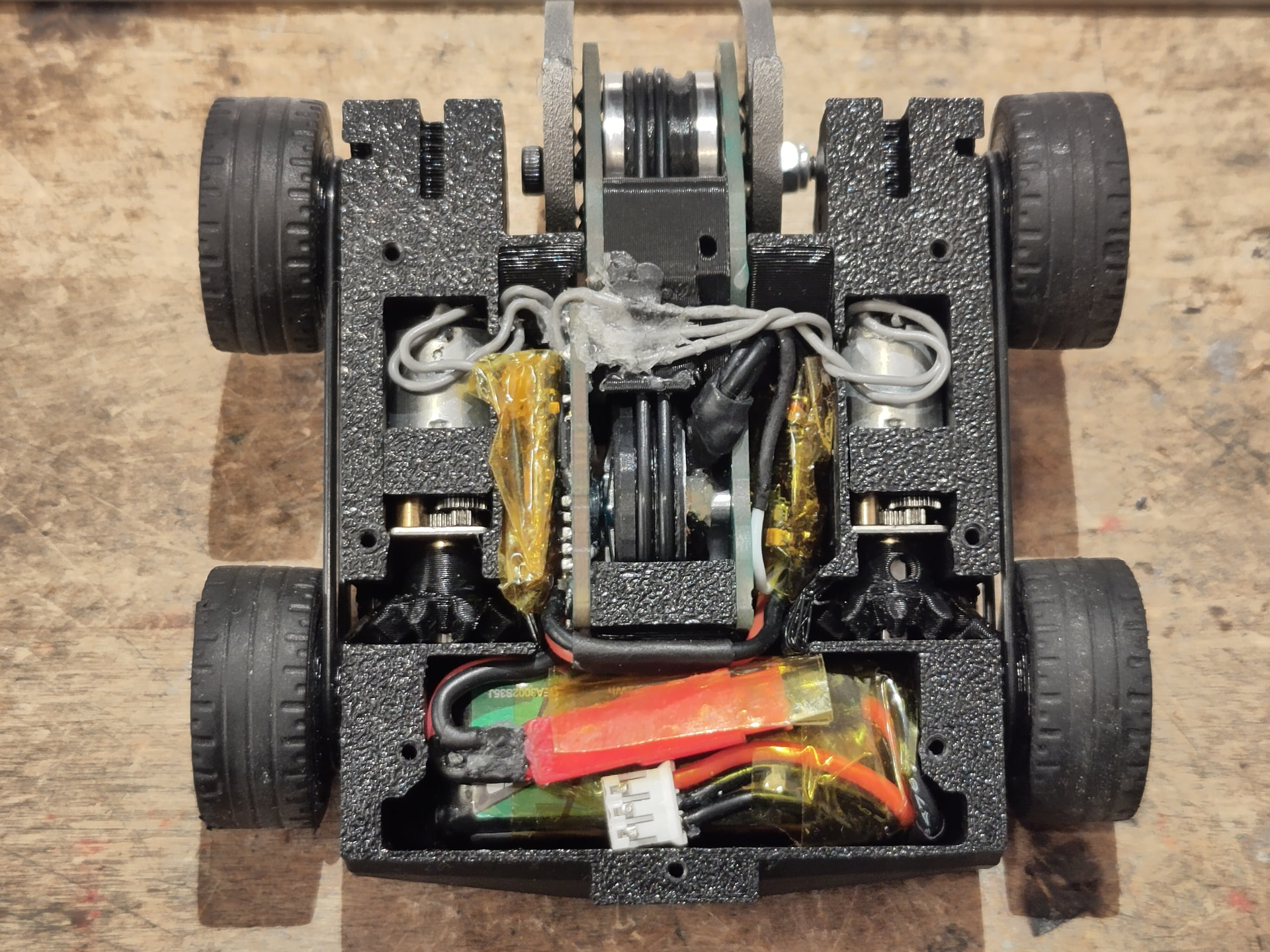
Several late-night Christmas CAD sessions later and several more days’ combined 3D printing time I have a CAD model and a mostly working prototype. Please ignore the “Cockroach connected to a computer in a 1990s science documentary” vibes, I’m using some spare electronics until final PCBs arrive, but it drives and the weapon spins up - first blood was a cherry tango can.

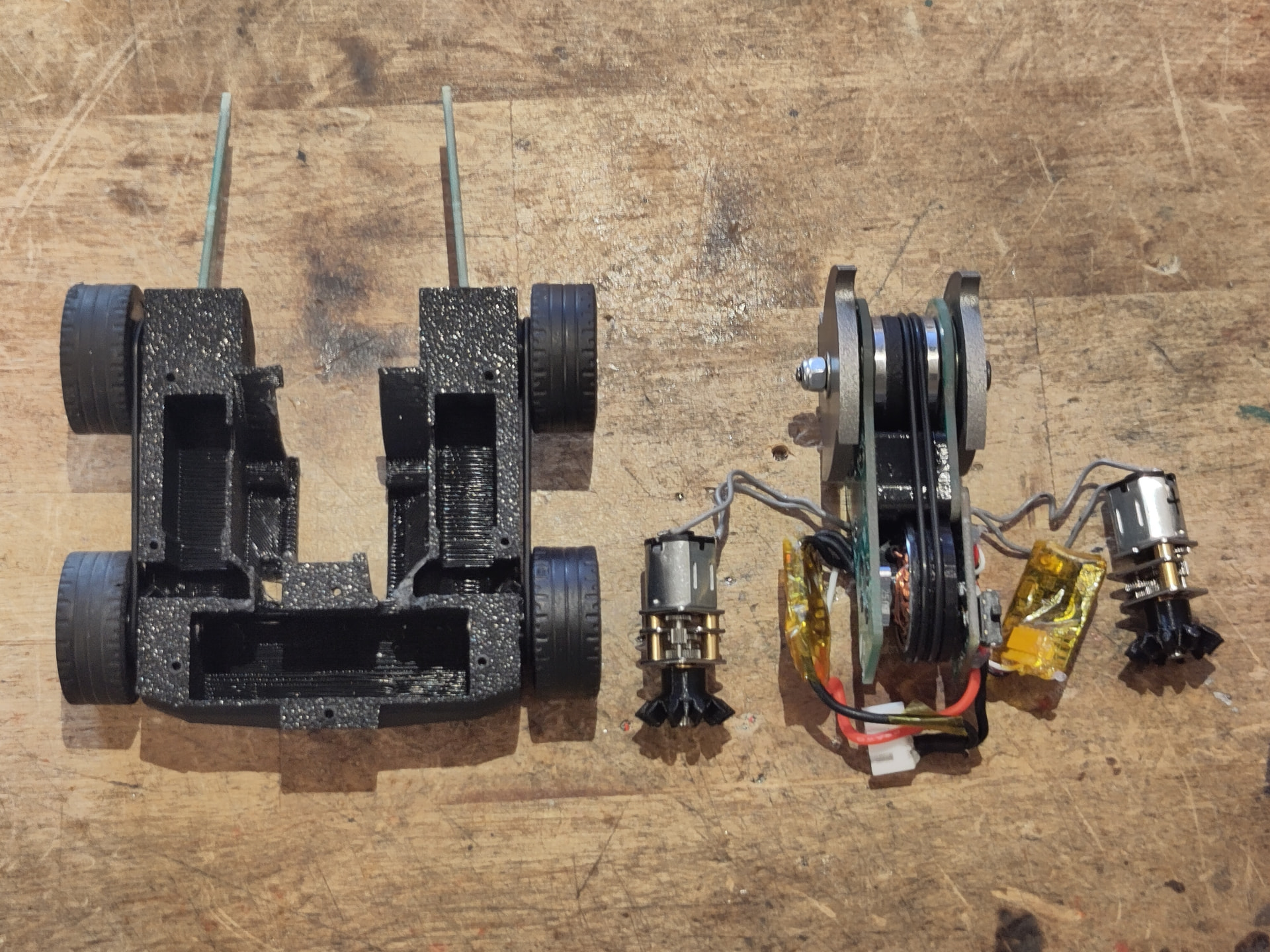
If you’ve seen my other robots you’ll probably spot some design cues. I’m re-using a slightly updated version of the 3D printed bevel gear setup from Birdemic, except this time with the primary driven wheels at the rear. To save some weight over Birdemic’s 3S setup I’ve dropped down to 2S, but am aiming for a similar drive speed by using 1500rpm motors. Similar wedge design to Fatal Deviant and Birdemic, but this time removable with screws so I can use a TPU wedge on a PLA-ST body.
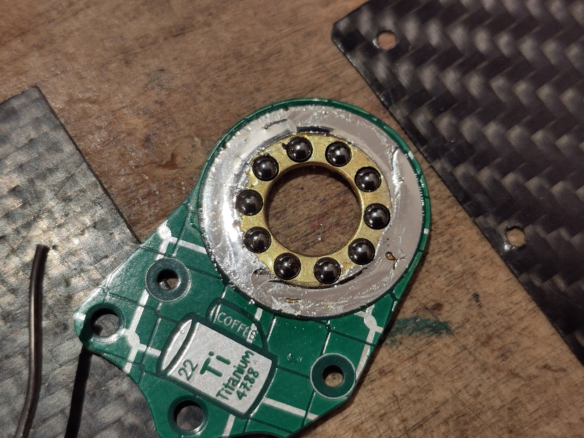
While the main body of the robot is PLA-ST (or possibly TPU, I need to do a test print and see if all the features work out in TPU), I knew I needed the weapon uprights to be as stiff as possible, so I have designed them to be fabricated as PCBs. Since 5x PCBs this size are about $2 plus shipping from the big Chinese fab houses this turns out to be a really cheap way to get precision routed FR4 parts with four colour graphics (dark green base, light green soldermask, silver tinned copper, white silkscreen). I’m not a great visual artist, so I usually go for the ultra-mininmalist look with my robots, but with all that artistic potential on offer it would be a shame to go to all that effort only to use bare green PCBs. I have thus handed artistic control for those parts entirely over to my mysterious friend Lucifer (their words not mine), no spoilers yet but I have seen some drafts and am extremely excited to see the results!
Of course, it wouldn’t be one of my builds without weird electronics. I’ve seen other people use PCB fab houses to make FR4 parts for robots, but I’ve never seen anyone do this. Maybe for good reason?


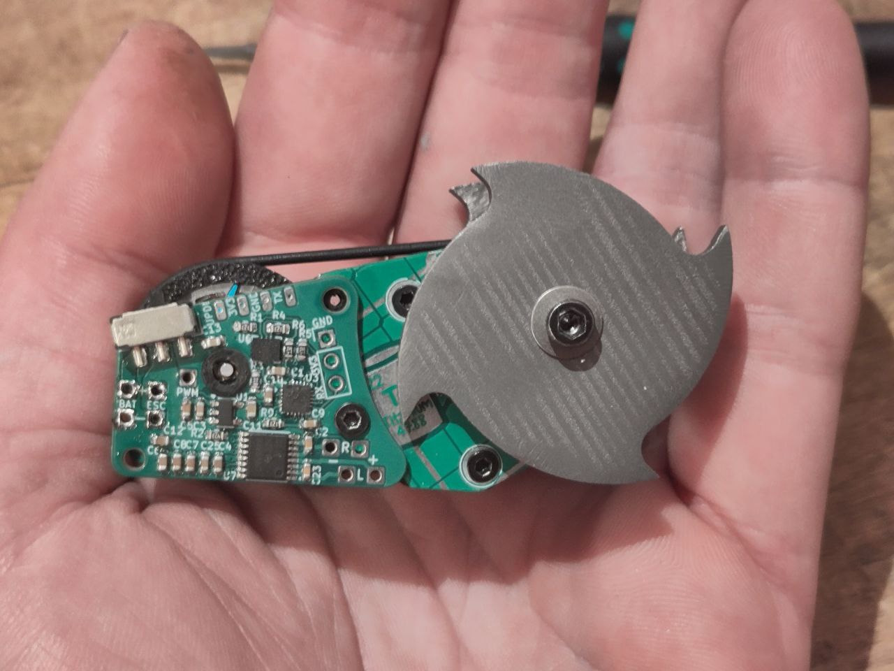
Yes folks, I made the the drive electronics structural. It’s the same core schematic as the Birdemic PCB, only without the brushed weapon drive channel and with the switch integrated. It’s then splatted onto a basic mechanical outline that I’d already defined in CAD. Everything just about fits! This amazing for packaging, because I essentially no longer have to account for any drive electronics. It is also amazingly risky, because if the board flexes enough the components will start falling off.
I have mitigated this in a couple of ways. The main (and easiest) change was just to increase the thickness of the drive PCB - it’s 2mm thick, whereas the rest of the uprights are the standard 1.6mm thickness. Those should now flex in preference to the drive PCB, although I have ensured that the other uprights are well triangulated to the body and composite baseplate - you can see the screw holes in the top of the main body in the photo above. The screenshot below shows how the TPU spacer between the uprights fits through the inner upright while the drive PCB sits on top between it and the main body.

Hopefully this feature lets the inner upright shift around on hits instead of transferring forces into the PCB. In this screenshot you can also see the little TPU isolation bongler that holds the tiny bronze bushing the motor shaft rides on. As a result of all this the PCB is only semi-rigidly mounted to the rest of the weapon assembly and motor. Just in case though, I’m going to pot the whole board in epoxy. Can’t be too safe.
The weapon has 2x 42mm discs. Four teeth because they look like ninja stars (rule of cool). JLC3DP says 9g and $8.20ish each from SLM titanium, which is absolutely wild. 3800KV 1604 motor with ~1.2:1 reduction gives ~180mph theoretical tip speed - not looking to end anyone’s day with a single roof shot, but hopefully spicy enough to keep people on their toes.
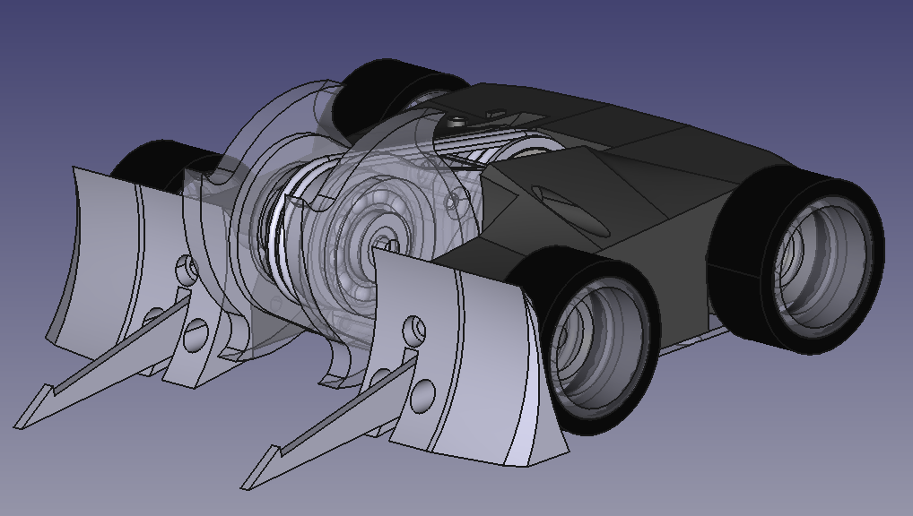
In all this excitement you might have forgotten about the “counter gyro” part of the title (I know I almost did). Maybe you didn’t and were wondering where I’d put the flywheel? Maybe this explains things:

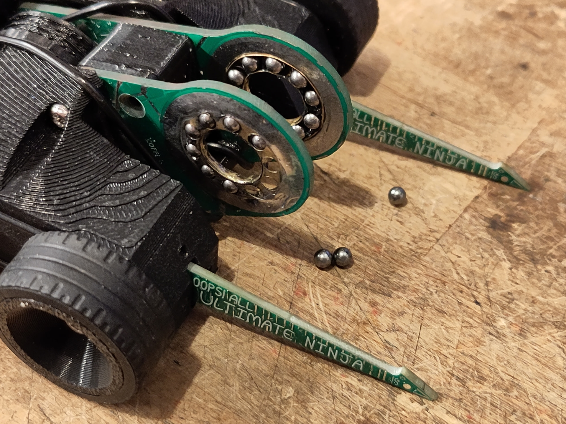
It also wouldn’t be one of my builds without an esoteric RC car callback repackaged into a robot. In this case I’m abusing balls. Ball bearings, I should clarify. As used in a ball differential.
If you’ve ever played with an RC car (or real car on jack stands) with an open differential, you’ll know that if you hold the centre section and spin one wheel of the vehicle, the opposite wheel will spin in the opposite direction. Most vehicles have bevel gears to achieve this, however smaller RC cars often have ball differentials, which provide much the same effect by using ball bearings rolling on parallel plates. This means that with just a little frame of reference change, a differential can be a reversing gearbox. Normally this is a terrible idea, because differentials have relatively fragile bevel gears inside. However, ball bearings are compact, and robust, and can survive some clutch action, and anyway once that antweight fight starts physics cease to apply anyway. Can I use them to spin a pulley one way and a weapon the opposite way?
Ball differentials aren’t optimised for continuous running, however. The balls only roll when the car is making a tight turn, or a wheel loses grip. They’re designed to have some inherent friction to improve their function as a differential. If you grab a wheel and pin the throttle something will get hot and unhappy pretty quick. There’s something else though that has two parallel plates separated by a number of bearings in a carrier. They’re also optimised to roll efficiently. And very cheap as a complete assembly. It’s a thrust bearing!

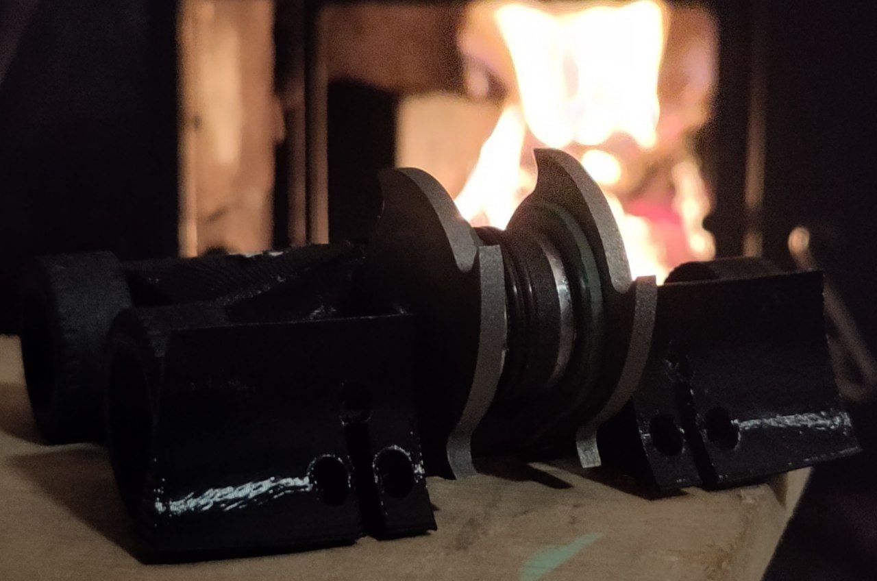
The bulkheads have the bearing carriers affixed. Currently superglued into PETG, but will be soldered into the final FR4 bulkheads.

Weapon hub stackup is a complicated one. The central hub is driven from the weapon motor via 2x o-rings. Pressed onto the sides are one side of each of the thrust bearing faces. This is slid in between the uprights. The weapon disks then slide onto the outside - the 3D printed versions also have thrust bearing faces pressed in, but I’m hoping to have the bearing groove feature baked into the final titanium parts. In the centre of the weapon disk is a smaller roller bearing, these align the disks and the hub axially and (fingers crossed) clearance the thrust bearing cages just enough to constrain the thrust bearings from climbing the grooves in the faces if required. It’s all tied together with a big screw, a locknut and some belleville washers.
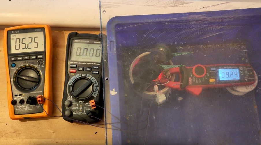
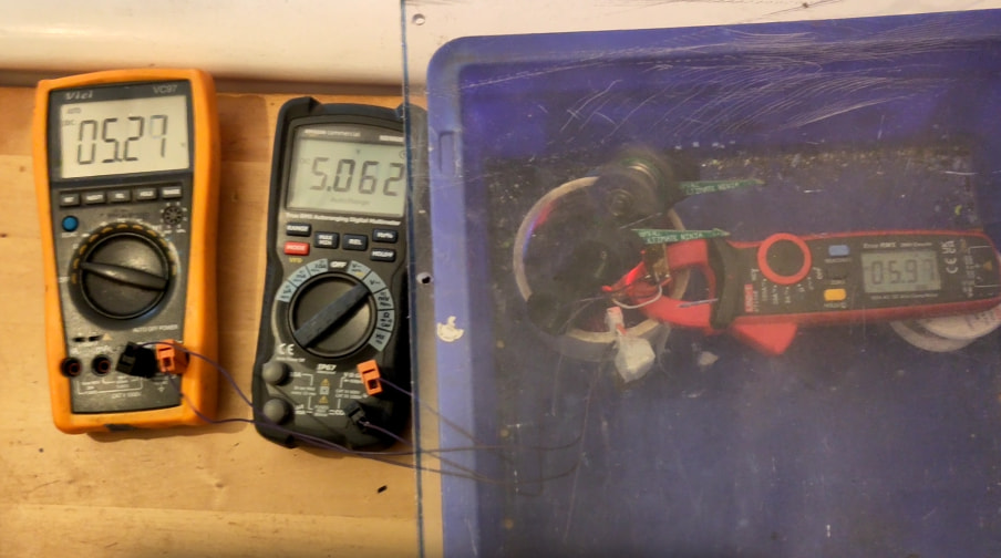
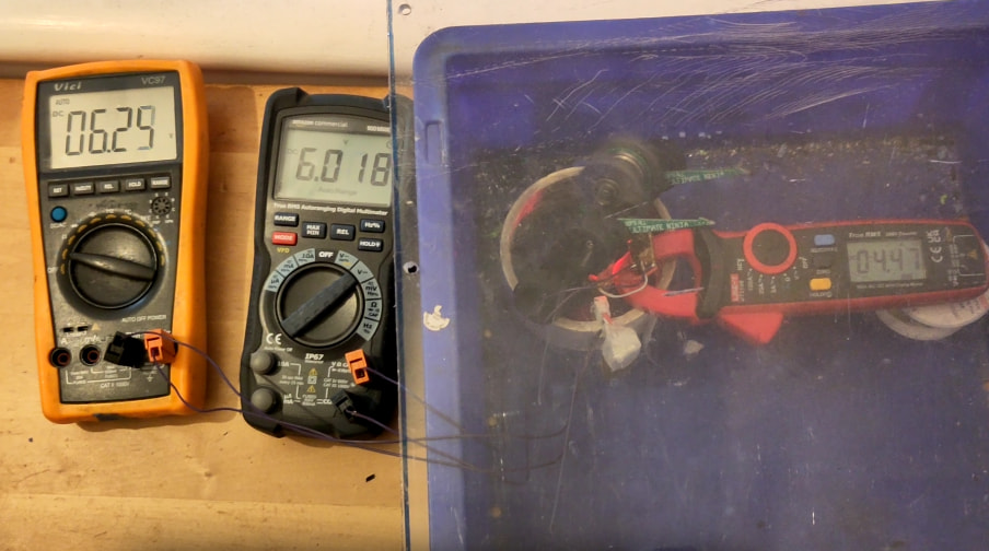
Does it work? Actually, yes! At least with plastic weapon disks.

Just like a ball differential, preload is touchy. Half a turn too tight and the motor can’t get things spinning (and if it does all the 3D printed rotating parts melt). 1/8th of a turn too loose and the weapon disks are barely coupled and take a couple of seconds to spin up and down. But get it right and it’s as smooth as any other badly aligned belt drive spinning at 30,000rpm. A little oil on the balls does a lot for smoothness too (I’m giving up make your jokes I don’t care).
Gyro isn’t entirely cancelled - there’s about 5g of spinning mass in the motor and another 4g in the pulley, while the total mass of the weapon disks is 18g, but if there’s left over weight I can put it into the pulley and negate more gyro. If I can’t, I’ve already negated about half of it. If I had the space available inside the bot I’d prefer a higher KV motor and a 2:1 or so reduction to the pulley, but smol bot > optimising the physics.
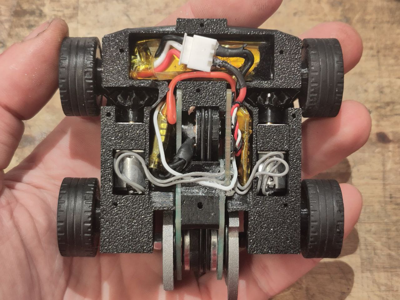
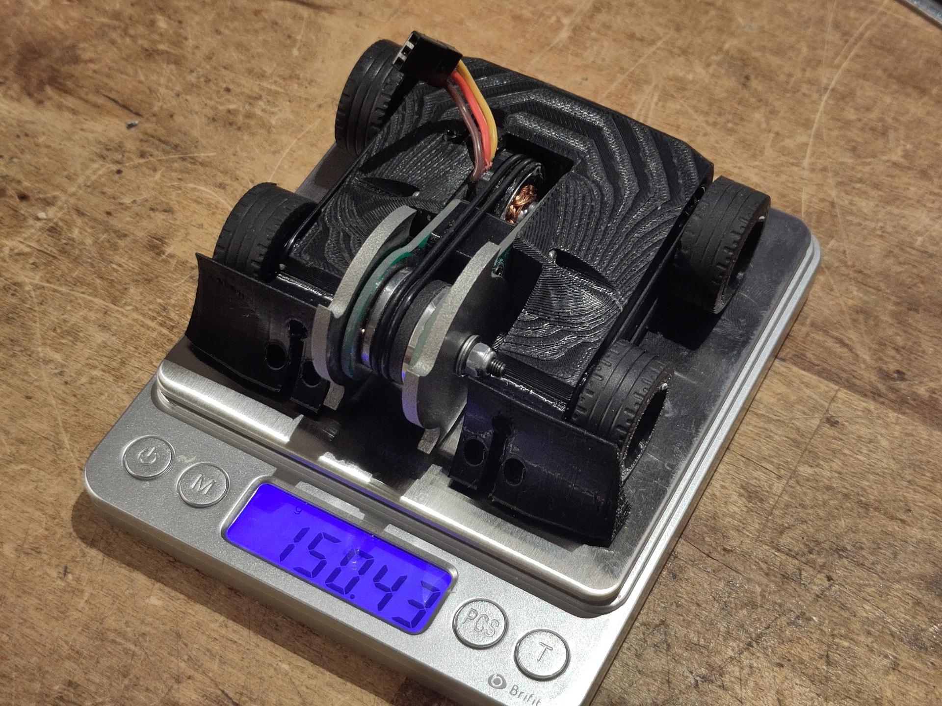
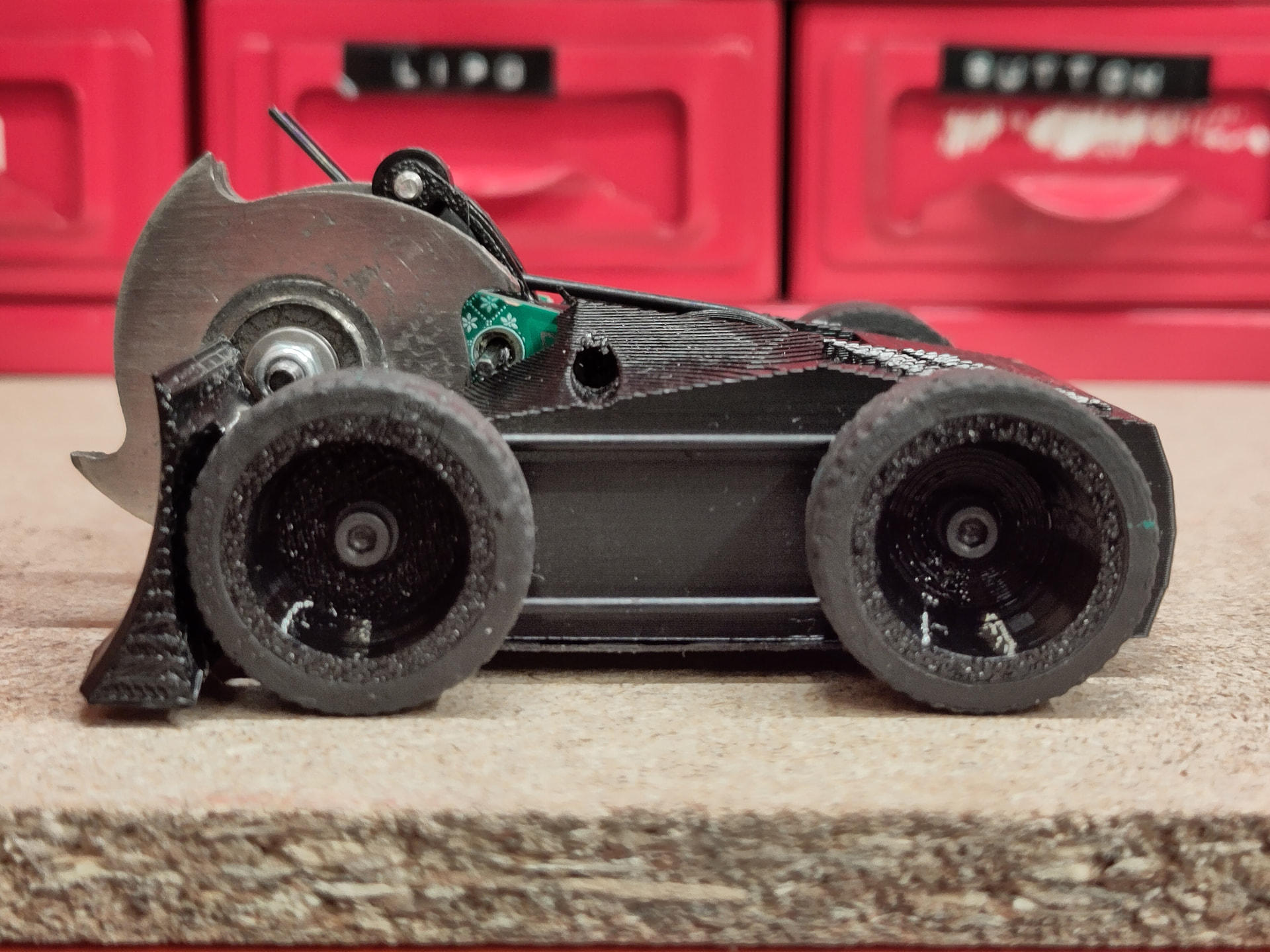
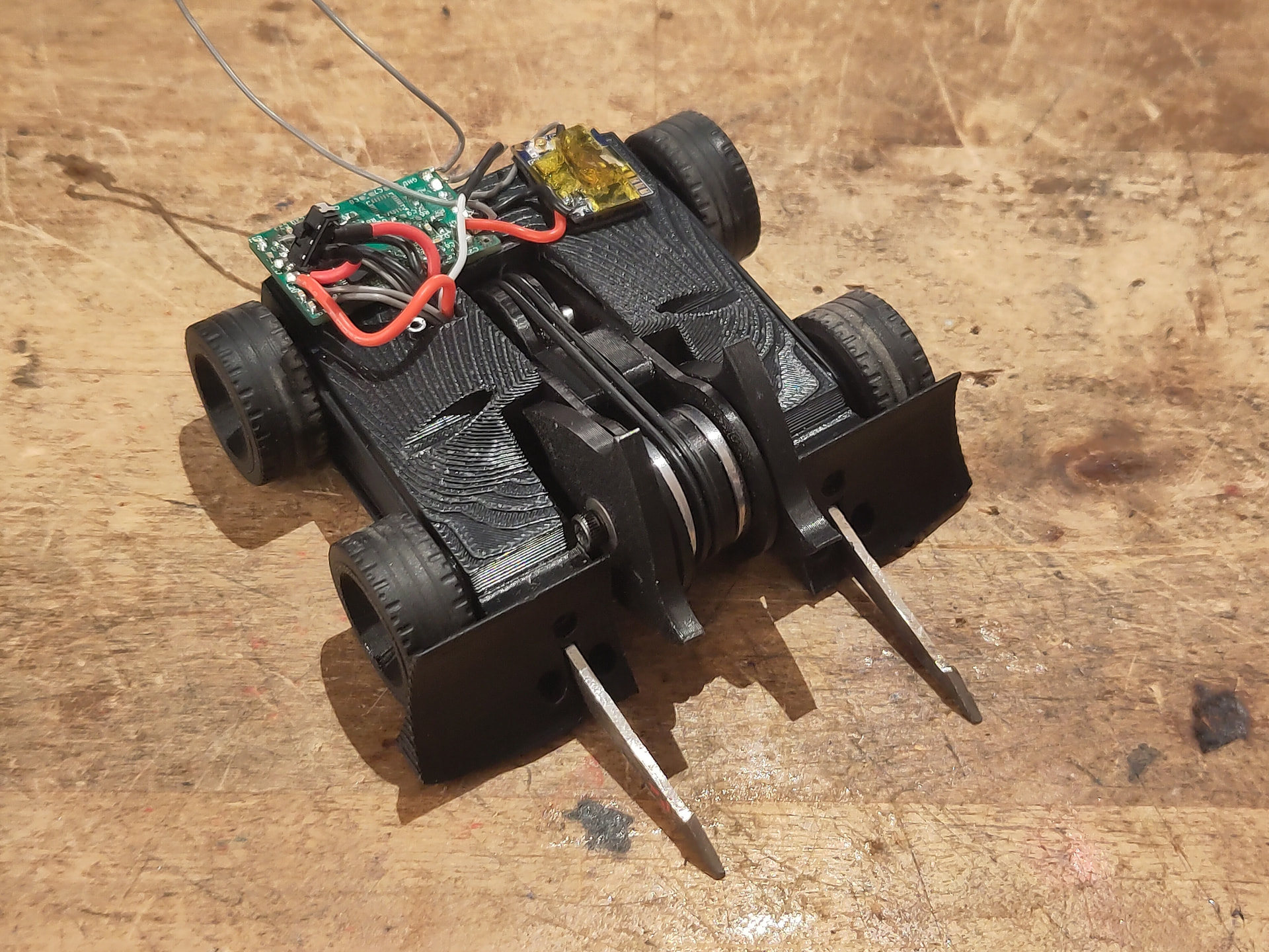
How smol?

Yeah that’s pretty small I guess.
Thanks for reading about my latest silly little robot, I will hopefully have it done for GROCS and/or ORCS. See you in the OOTA zone.