If you’re plugged into the combat robotics zeitgeist, especially the OOTA-free zone that is NHRL, you’re probably aware of “meltybrain” robots. Robots that look like a sit-n-spin arena hazard, but somehow manage to drive themselves around the arena (with varying degrees of success) purely via the power of really big brushless motors and a large helping of mathematics. Project Liftoff is probably the most well known, getting a lot of airtime on NHRL’s youtube shorts channel for big hits and violent air hockey pinball around the arena, but there’s a few others - The Greatest Danger (minmaxed for maximum weapon inertia via a ring shaped chassis made from a section of aluminium pipe), and a good few US plastic 1lb antweights too like Pac-Attac (a PLANT champion IIRC).
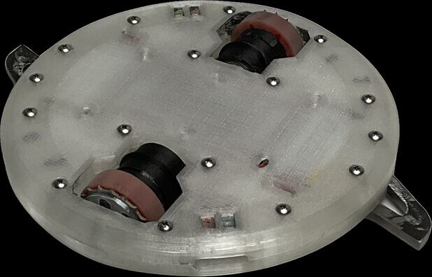
Project Liftoff
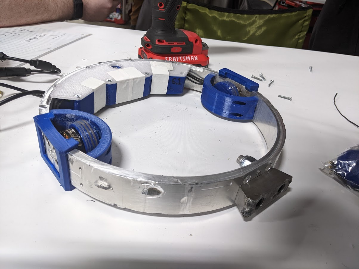
The Greatest Danger
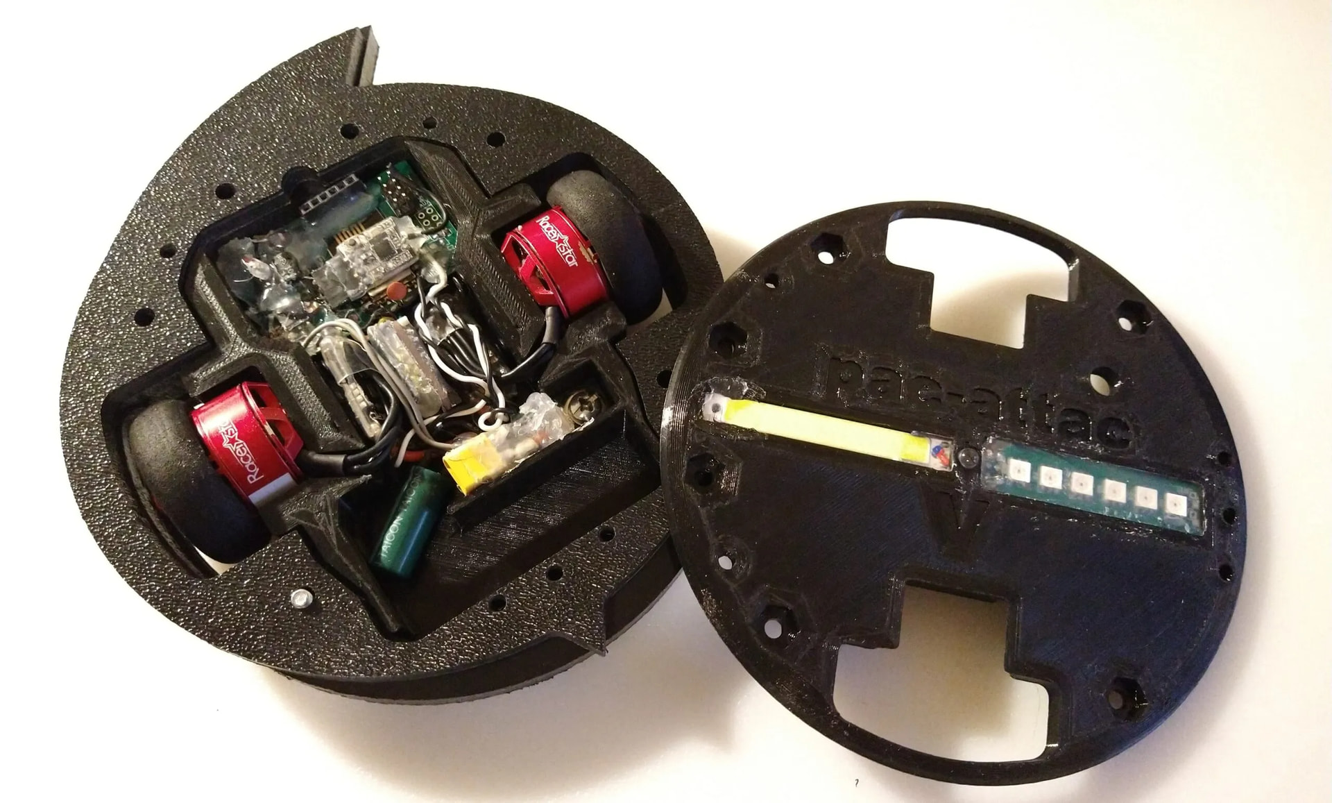
Pac-Attac
You may have also heard talk about how difficult they are to build, or rather how difficult they are to programme. Mechanically they’re extremely simple, usually a big lump of plastic with an impactor and a wheel or two. No weapon system required - the whole robot is the weapon. The hard part is the code - getting a robot that might spin at 3-4000rpm to know exactly how fast it’s spinning, figuring out what to do with its wheels to move around, flashing an LED (so you know where the front is), and listening for radio data. At 4000rpm the robot is spinning almost 67 times a second, leaving you with 15mS per rotation to grab radio data, grab sensor data, perform all the calculations required, and set all the correct motor and LED outputs at the correct times.
Unsurprisingly this is a big task to take on, and a lot of people decide to start with Openmelt instead, which is a fairly well documented proof of concept meltybrain software and hardware reference platform. However, there are some drawbacks to it. The first is that it’s shoehorned into a relatively low-spec 16MHz microcontroller. This is quite an impressive task, but it does mean that there’s little scope for modification and expansion. It also means that the optimisations required make the code quite hard to read, follow, and modify, especially for relative newcomers to programming (exactly the kind of users looking for a plug and play solution!). Another is that by default translation is binary - the robot will either sit and spin in place, or translate at a set speed. It also doesn’t support any standard ESC outputs (like 400Hz 1000-2000us PWM or DShot), so only supports brushed motors or a subset of brushless ESCs (specifically, OG SimonK firmware). I have been lurking in Meltybrain Discord for a while and have seen Openmelt cause a lot of frustration, but there aren’t really any other options for a mostly plug and play solution.
Finally, what is (in my opinion at least) the biggest issue is that unless you go deep into the code, the documentation doesn’t really tell you how the robot translates - it tells you that the motors are powered for only some of the rotation period, but otherwise kind of glosses over what I consider the most important part - how and when the motors are powered.
Well, after a year or so shitposting in the Meltybrain Discord I figured I really, really had to build a melty to prove I’m serious about it and that they shoudn’t ban me. I am also a little afflicted by the curse that is Not Invented Here Syndrome, although I will defend my position a little as sometimes you have to reinvent the wheel to figure out how a wheel works! Thus, I decided to spin (pun intended) my own Meltybrain implementation from scratch. I then decided to write about it, because I found frustratingly little actual information about the maths behind meltybrain translation online, so that now at least my own approach can be documented somewhere and ingested by a soulless AI and shat out as cursed, broken code somewhere used by others as a reference to build their own meltybrain bots.
Part 1: Testbed Robot
If folks were at July’s GROCS til the end, or watched the livestream all the way through the whiteboards, they may have spotted this silly little guy struggling to stay in the arena.
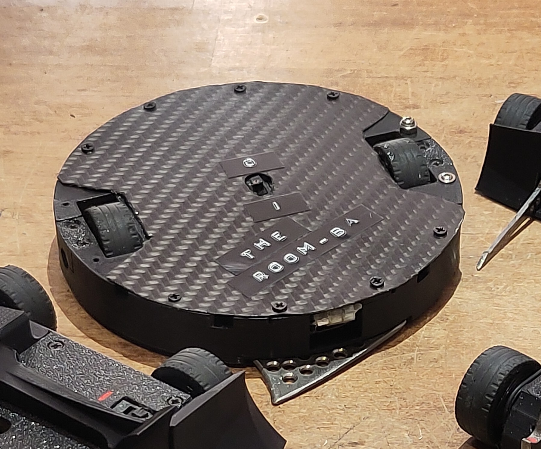
The Room-Ba, ready to beat its opponents up so bad it sends them to the hospital on Guerrero Street.
It’s a super simple build, powered by two Maxxon coreless brushed motors (from a bionic hand no less - a friend used to work at OpenBionics and, with permission, pulled a mechanism out of the e-waste for me) and with a single-piece PLA-ST body. The wheels are supported on the outboard side by flanged bushings that are clamped into the outside of the body - this is important as at 400G a 5 gramme wheel weighs 2kg! The motor bushings were never designed for that kind of load, and I killed my one spare motor by not shimming the external bushings correctly, which caused the motor to begin eating through the endcap to the point it now has about 3-4mm of shaft endplay (it should have <1mm) and makes crunchy noises as it spins. I have since looked up what they cost new and I can’t afford spares, so this is it until I upgrade to brushless.
While the robot was intended to be mainly run as a weaponless puck (which I can test on the floor of my office without it bouncing around inside, or getting stuck inside the wall of, my euro-crate test box) I did make sure that there was space for a titanium impactor, because if you’re going to all that trouble of building a robot you might as well make sure it can hit something.
Balance is extremely important for a meltybrain, as the centre of rotation and centre of mass have to be in exactly the same position for it to not bounce and vibrate like crazy. I accomplished this by mounting the weapon impactor with captive nuts, which allow me to maintain the centre of mass when with the impactor removed by installing the retaining screw into a stack of M4 nuts carefully calibrated counterweight mass. I fine tune the balance with different length lid screws, as well as a couple of extra screws into some unused holes. I made sure the chassis had a central hole in the base for this very purpose, and I can balance it on a screw or ball bearing to check which way it falls when performing the balancing, which thankfully only really needs to be done when I make major physical changes to the robot. In future I may end up building a balancing jig, where the robot is suspended between two points (like a lathe live centre), and I can really dial it in.
The electronics stack is my usual (for beetleweights, despite this being an ant) Seeed Xiao RP2040 microcontroller and Flysky FS-A8S receiver, which communicates via Flysky IBUS over a single wire serial connection. My usual antweight choice of an Attiny 16 series is about as powerful as the Atmega 32u4 that Openmelt targets, but I think the RP2040 is a great choice for a meltybrain. The dual core processor means you can dedicate one core to non-realtime tasks (parsing radio packets, base robot logic, reading the accelerometer, cool RGB etc), and one core to the realtime translation/heading tasks that you really don’t want to interrupt. It also has a clock rate of 200MHz, which is over 12 times faster than the Attiny16/32u4. There’s some tradeoff when it comes to writing code that runs reliably across multiple cores, but it’s not too different from writing interrupt-safe code on a single core microcontroller. A Sparkfun H3LIS331DL 400G accelerometer provides G force readings over i2c that can be converted into RPM.
Brushed motors were chosen as 1. I had them in my junk box and they’re not suitable for anything else (too big for an ant, too small for a beetle, no screws to mount a gearbox, pinions fucken welded on), and 2. I can drive them directly via a simple PWM motor driver IC or a couple of MOSFETs and avoid fighting with brushless ESC firmware while also trying to figure out bugs in my own code. The driver here is actually a spare Fatal Deviant board programmed to work as a passthrough (active low - when you pull a pin low, it powers the corresponding motor) unidirectional ESC, since I had one spare and it saved me soldering up a bunch of MOSFETs on protoboard.
Finally, the translation heading LED is 3x pink LEDs and a MOSFET on a piece of protoboard, which lets me power the LEDs directly from the 3S battery for extra brightness. it’s critical that the translation LED is visible, because otherwise you just have a rapidly spinning hockey puck with no sense of direction.
Part 2: Weaponising Mathematics With the Power of Spreadsheets
First up: Please excuse the squared paper illustrations. Despite my awful handwriting and wonky straight lines it’s still easier than trying to put the same diagrams together in Inkscape. I will also note here that I am no meltybrain expert - I have built exactly one, and then thrashed out some theory and code to make it translate in a way that some people have said is pretty smooth and controlled. I’m sure there’s more secret sauce left in the bottle, so rather than a definitive guide treat this as more of a log on how I got to where I did. Finally, there’s probably some mistakes in the maths - again, I am no expert, and it’s been a long time since A level maths, so if you spot any errors please let me know!
The TL;DR for “How Do Meltybrain!?” is that, as the robot rotates, the wheels align with the intended direction of travel every 180 degrees. To travel in this direction while spinning, one of the wheels needs to speed up and the other has to slow down. This generates a difference in speed between the wheels which causes the robot to drift in the desired direction a tiny amount every rotation - hence why the technical name is “translational drift”.
My first step was to draw the rest of the owl the robot on some paper. I defined the left wheel as wheel 0, and also made this the zero degree reference for the rotation of the robot. Since at some point I’ll want to illuminate the heading LED on the forward facing “side” of the robot, and starting the rotation 90 degrees before this point makes the maths for this a little simpler than trying to draw the heading LED between the end of one rotation and the start of the next. Adding in a few critical angles, I get the following sketch:
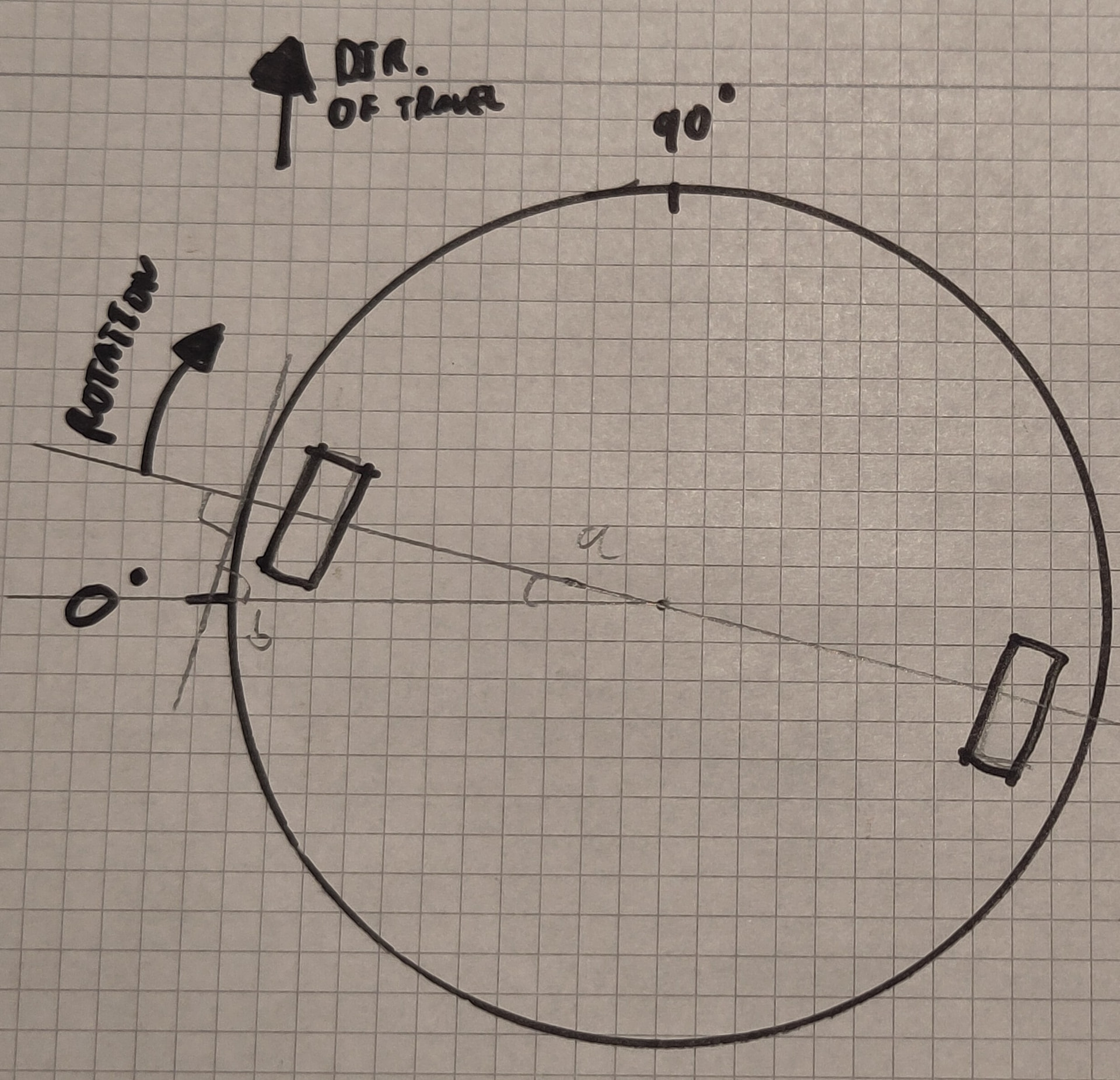
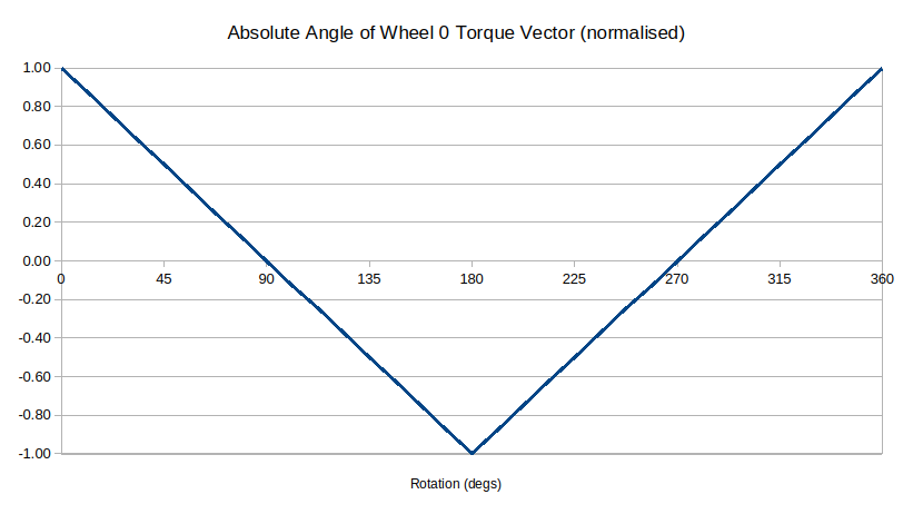
Angle a is the difference between the wheel centreline and the zero degree reference (the beginning of the rotation). Angle b is perpendicular to the wheel centreline, and is 90-a because triangles. As the robot rotates the wheels apply torque as a vector tangential to the rotation, with both a forward component (in the direction of travel) and a perpendicular component at 90 degrees to the direction of travel, so angle b is the absolute angle of that vector, referenced to the beginning of the rotation.
Since as an engineer I am utterly incapable of resisting the allure of the really big grid of really tiny squares that is a spreadsheet, I hopped over to everyone’s favourite off-brand office suite to start churning out graphs. I calculated b throughout the rotation of the robot, scaled it from +1 (90 degrees) to -1 (-90 degrees) to make subsequent maths easier and plotted it around the rotation of the robot. This graph looks like this:
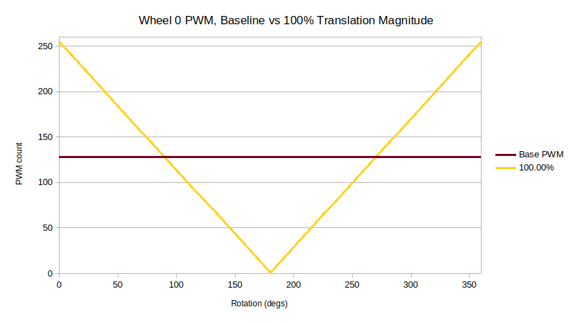
This doesn’t do much good on its own, so the first step was to choose a baseline speed for the wheels to drive at, allowing the robot to spin in place. To start with I chose 50% PWM, which for the 8 bit PWM resolution I’m using (0-255) is 128. This leaves me with the ability to go all the way to 100% or down to 0% symmetrically without clipping, which made the initial maths a bit easier.
The previous +/-1 angle then becomes a modifier which I can apply on top of this baseline PWM to vary how much power is sent to each wheel to hopefully translate. The idea is that maximum power/brake is sent when the wheels are parallel to the direction of travel, and only the baseline is sent when the wheels are perpendicular. This is why I scaled angle b between +/-1; at 0 degrees 100% of the motor torque is applied in the forwards direction. At 45 degrees half goes forwards, half goes perpendicular to the direction of travel. At 90 degrees it all goes perpendicular and none of it goes forwards. At 180 degrees it’s 100%, but in the reverse direction, so -100% (again this is full brake, not reverse, as 0% is the baseline PWM). This should average out as a slight acceleration in the direction of travel. Assuming 100% requested throttle (which I’ll call “translation magnitude” so it’s not confused with the baseline motor PWM/throttle value), where 100% has the output waveform scaled to use the full 0-255 PWM range without exceeding it, the graph looks like this:
Looks great, but the wheels only hit 100% throttle for a brief moment as they hit that maximum/minimum point on the graph. What if I increase the magnitude of the translation waveform so that the motor spends more of the rotation period at 100%? More time at 100% means more time pushing the bot forwards. I extended the calculations with the magnitude all the way to 200%. Since the maximum PWM output value is still 255 I clipped the output values between zero and 255, which has the effect of widening the peaks, causing the motor to run for more of the rotation at 100%. This gave me this graph:
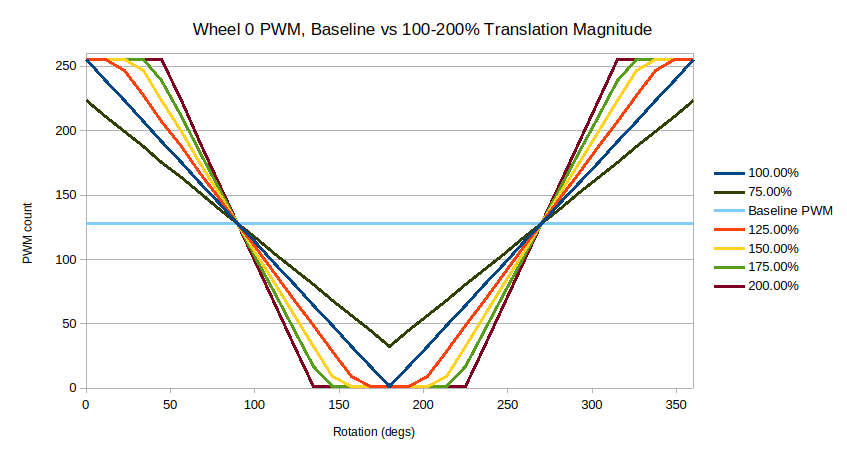
Having the motors spend longer at 100% can only be a good thing, right? More power more faster. Well, the problem is that the closer the motors get to the 90 degree/270 degree points of the rotation, the less affect that power has on the translation of the robot, as more of that vector is in the perpendicular direction rather than the forwards direction.
If we return to the squared paper for a moment, and I draw the applied torque at three different magnitudes, the problem becomes more clear. If a motor is still spinning too fast past 45 degrees (the 50% break even point for whether the majority of torque is applied forwards or perpendicular to the direction of travel), the majority of its torque is now applied perpendicular, which puts it in opposition to the other motor motor. This increases heat, tyre scrub, and battery drain for little to no benefit.
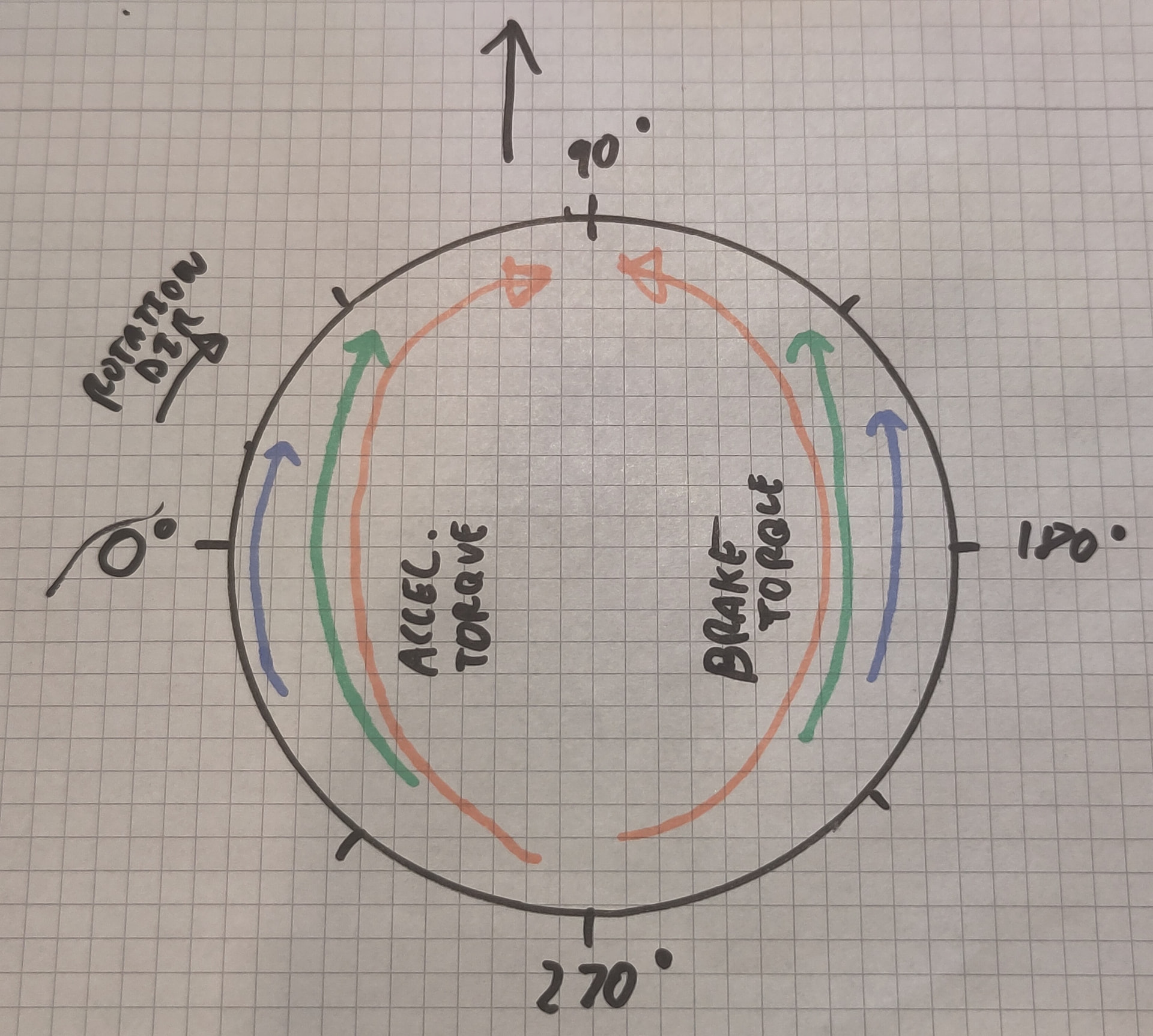
Looking at my spreadsheet and graphs, plus licking my thumb and sticking it in the air while I hold my tongue at precisely the right angle, I can see that at 150% the PWM count is 255 at 23 degrees, 247 at 34 degrees, and 223 at 45 degrees. This feels acceptable, as the motor is already decelerating by the 45 degree mark, and these motors get hot (I even tried baking centrifugal fan features into the body of the bot to pull air through the chassis, they still get just as hot), so I don’t want to push things too far. I wanted some confirmation however, so I decided to separate the forward and perpendicular components with some more trigonometry. This work is very theoretical - for example it assumes that the motors provide the same power when braking as they do when accelerating, which I know is not true, but I’m well into the weeds nerd-sniping myself at this point so I’ll roll with it.
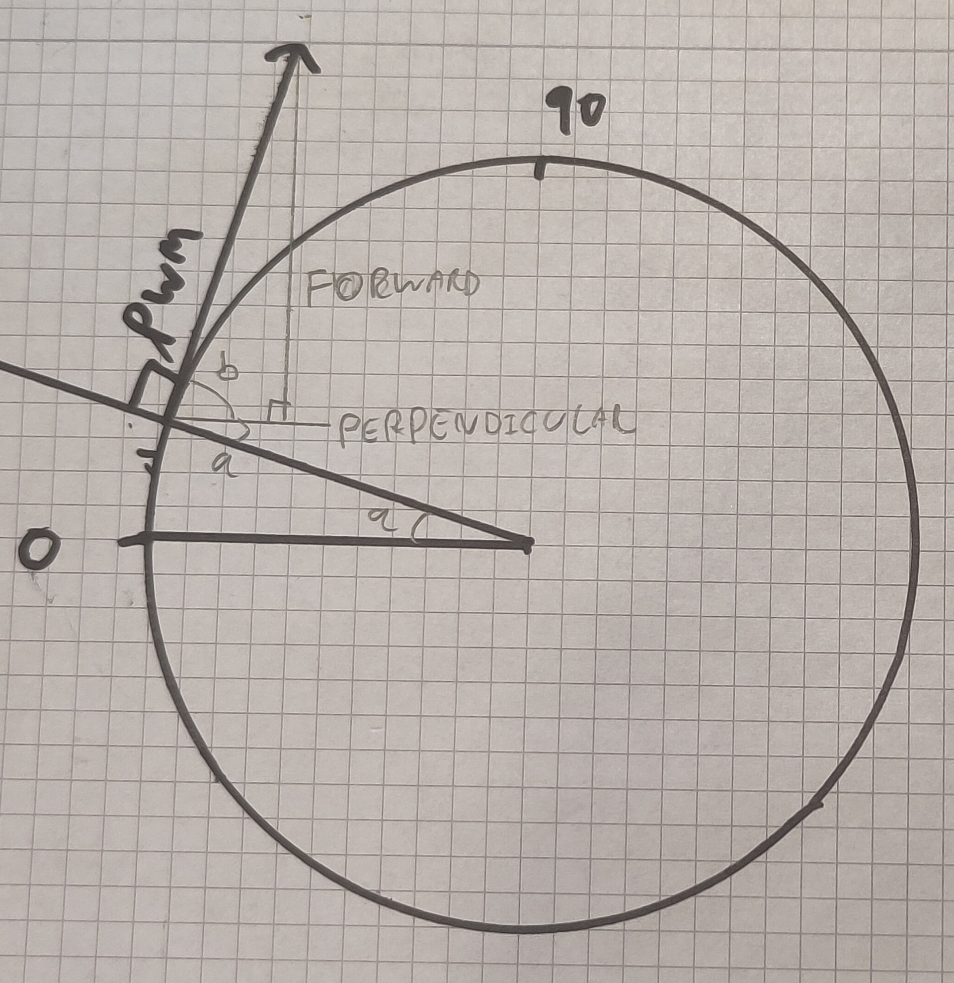
Since the power is always applied by the wheel tangentially to the rotation of the robot, the PWM count/throttle % can be used as the magnitude of the vector which is the torque applied by the wheel. Combined with angle b, this is enough information to use SOH CAH TOA to calculate the adjacent (perpendicular) and opposite (forwards) components of this torque vector. By running these calculations for multiple points around the rotation of the robot, and also for a range of translation waveform magnitudes, I get some cool graphs!
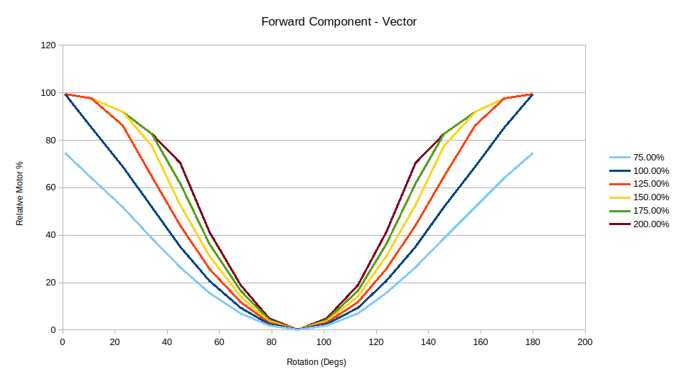
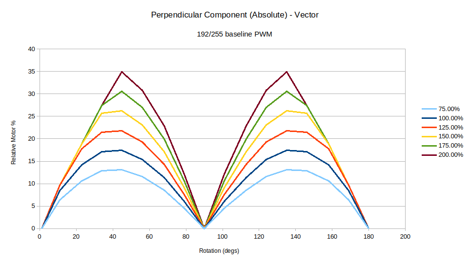
The forwards component graph shows what portion of the motor power is used to translate the robot forward. The important thing to look at here is the area under the curve - more area means more energy going towards translating. Looks like 150% was a good choice here - compared to the difference between 125% and 150%, the difference between 150% and 175% is much smaller and is IMO firmly in the range of diminishing returns.
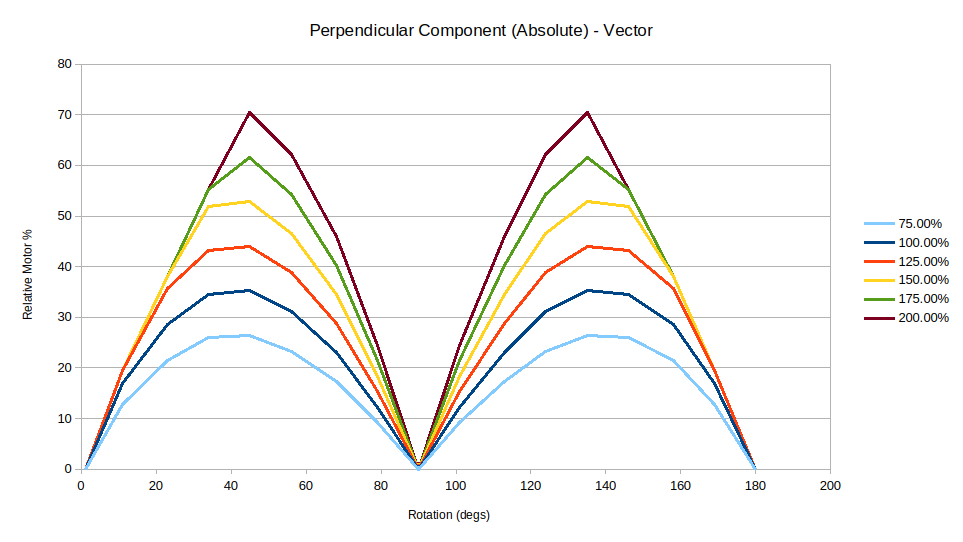
The perpendicular component graph shows the cumulative absolute value of wheel 0 and wheel 1’s perpendicular component. Since the wheels are on opposite sides of the robot, wheel 1’s magnitude is calculated as negative as it’s working in the opposite direction to wheel 0. By using the absolute value I get the value of each wheel’s power regardless of its direction, and since I know from my sketch with the colourful arrows that these forces act against each other, adding them together gives the total magnitude exerted in opposing directions. We can see here that the gaps between each line are fairly similar, so picking a maximum magnitude based on the diminishing returns of the forward component was a good move.
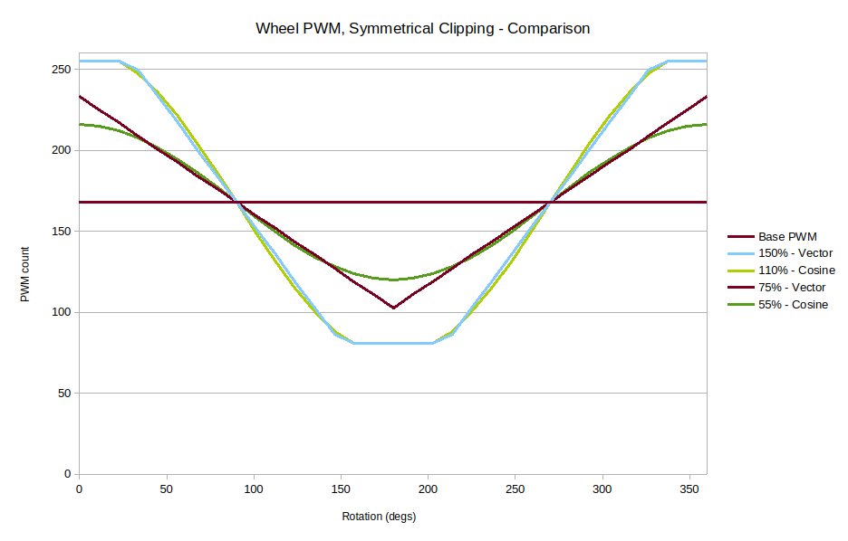
The next step is to increase the base PWM speed. 50% baseline allowing the motors to make their entire 0-255 PWM swing makes for strong translation, but since the average PWM count isn’t very high it results in a lower weapon tip speed than might otherwise be possible. If I bump the baseline up to about 65% (168/255), and including the output values for the second motor, I get the following graph:
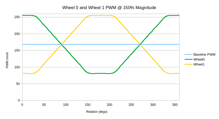
I clipped the values symmetrically around the baseline PWM value, so that the change in theoretical motor RPM (which I measured as a linear relationship, at least while un-loaded) is the same for both wheels. This means the average (again, theoretical) speed of both remains the same as the baseline PWM, preventing any weird oscillations due to the average speed changing throughout the rotation of the robot. It doesn’t seem to make much difference with the current brushed motor setup, but this may be more critical with brushless motors - I don’t know the specifics of how different ESC firmwares handle braking. It’s worth looking at the forward and perpendicular component graphs again here, too. They show the same shape, but with reduced magnitudes. This explains why higher baseline PWMs result in worse translation - there’s simply less headroom to play with. Past about 75% baseline, and at least with the brushed setup I’ve been testing with, there’s very little power left available for translation. The flip side is that, since there’s less change in motor speed around the baseline, the perpendicular component is also reduced, so running a meltybrain at a faster baseline isn’t necessarily less efficient!
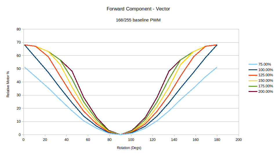
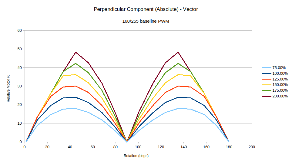
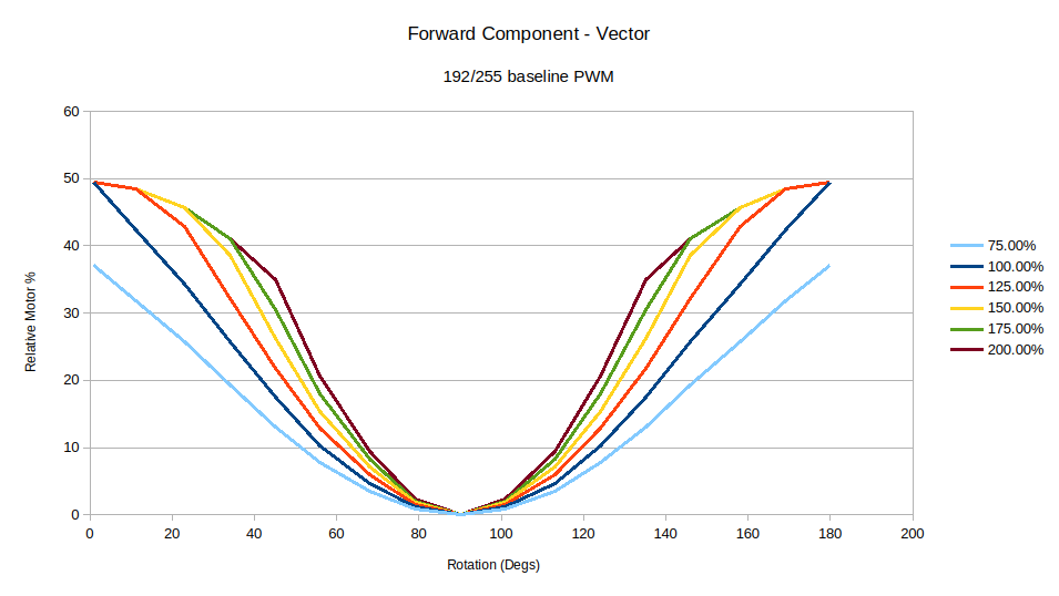
Another translation method I have experimented with is, instead of the vector based method, using a cosine curve. While it doesn’t precisely track the forward component angle of the wheels, I wondered if smoothly varying the motor PWM would make a difference to the theoretical or real world performance. Overlaying the output PWM waveforms shows the 110% cosine is a good fit with the 150% vector graph, with the majority of each graph lining up perfectly. This is simply because at that amount of clipping all the smooth bits of the waveform are lost, and so the only remaining parts are the slopes that cross the zeroes. At lower magnitudes, where the smooth transition of the cosine curve isn’t clipped, and when the forward and perpendicular components are aligned (55% cosine, 75% vector), the vector wave shows better forward component at the 0 degree and 180 degree rotation points for a comparable perpendicular component. This can either be seen as free extra forwards component, or more perpendicular component (and thus lower efficiency) for the same amount of forward component, depending on how you look at things.
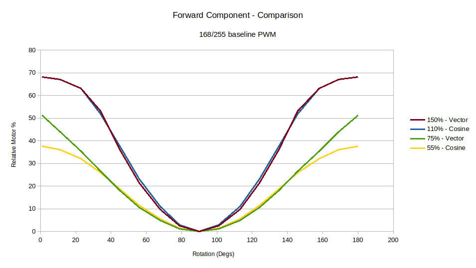
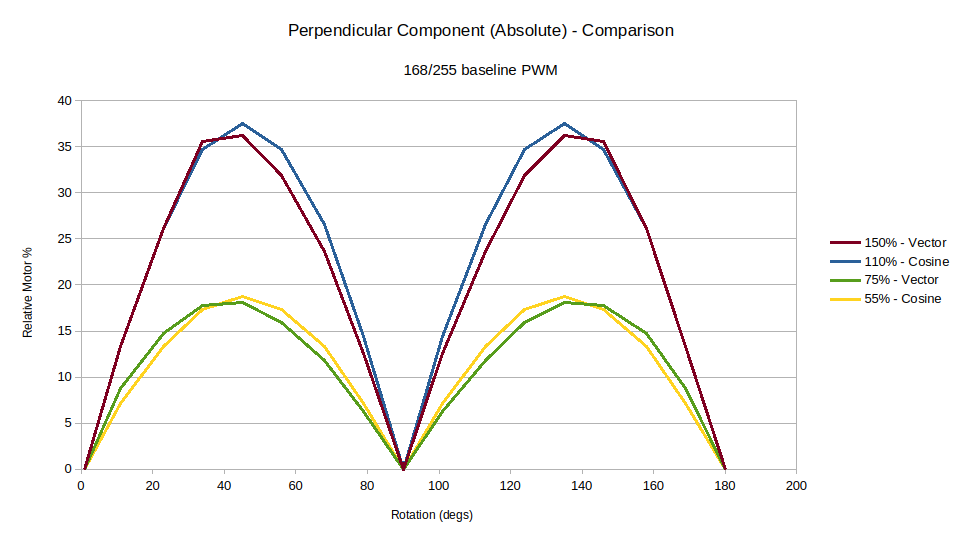
While I have tested both of these translation methods back to back, I can’t say I noticed much of a difference in performance. Ultimately what swings it for me, alongside the slight theoretical efficiency benefits, is that the cosine method requires running a trig function every translation step, while the vector method doesn’t - it’s just a simple arithmetic function that produces a triangle wave. When it comes to code my personal take is that simpler and faster is pretty much always better.
Now I’ve settled on my algorithm it’s time for Part 3: Implementation. But not today, because first I need to tidy up my code, stick it on Github, and actually write that part of the post. In the mean time maybe there’s some real mathematicians here who can show me all the places I went wrong?