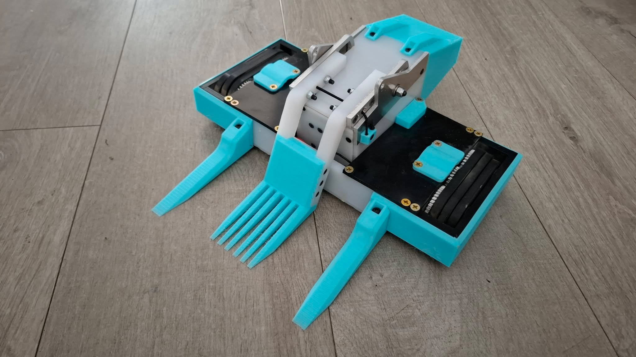
DesktopLauncher - how to make a flipper unnecessarily complicated

A few years ago, I made an antweight called Crash to Desktop. It was an attempt to build a Blip-style flywheel flipper in the 150g weight class - well, 225g because I also decided it was going to be my first shuffler. It ‘worked’, in that the flipper mechanism did function, however, it was a pitiful flip and it only ever competed in one event. I did attempt a couple of revisions but they never got past initial CAD work.

Fast-forward to November last year, I started thinking of things to design with an intention to enter it into 2026’s New Bloods event. It was a toss-up between scaling up Stack Underflow or attempting another flywheel flipper, and I eventually settled on a flywheel flipper - I felt that with a few more years of building and designing experience under my belt, and some experience with shuffler systems from Overclocked, I felt that it was time to attempt it again.

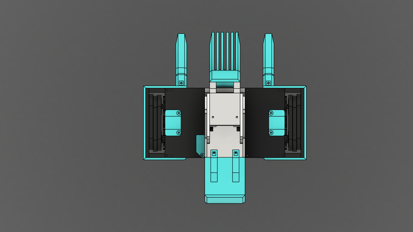
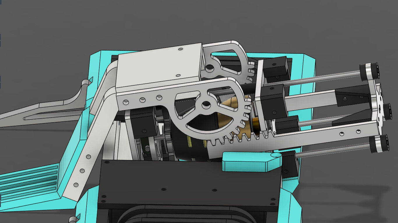
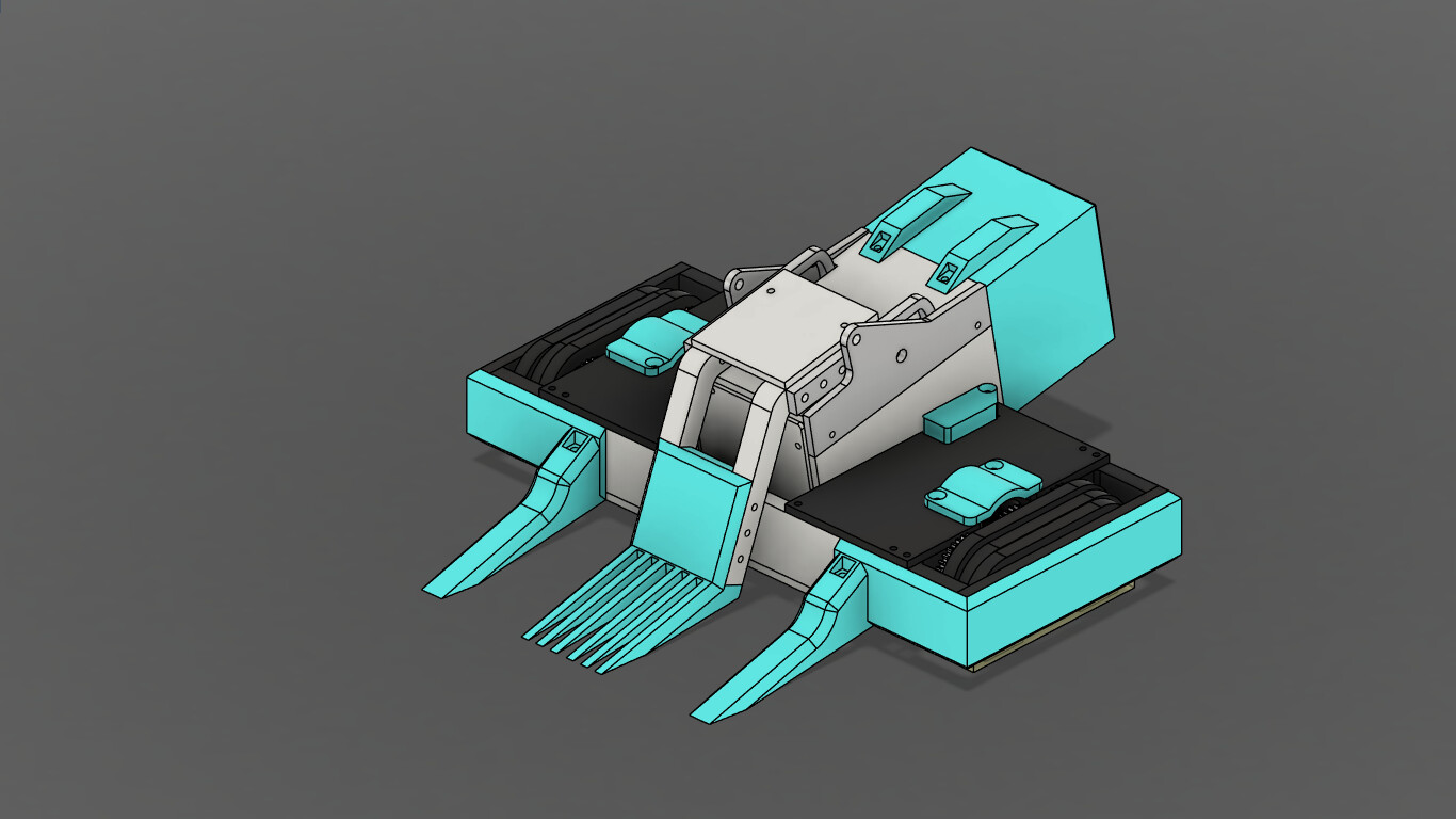
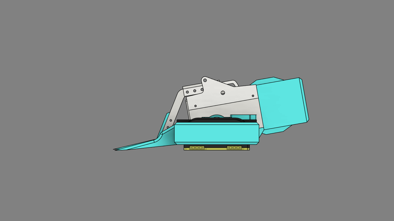
Going a bit out of order, here’s the completed CAD. The following posts will go back in time to how I ended up with this.

5 Likes

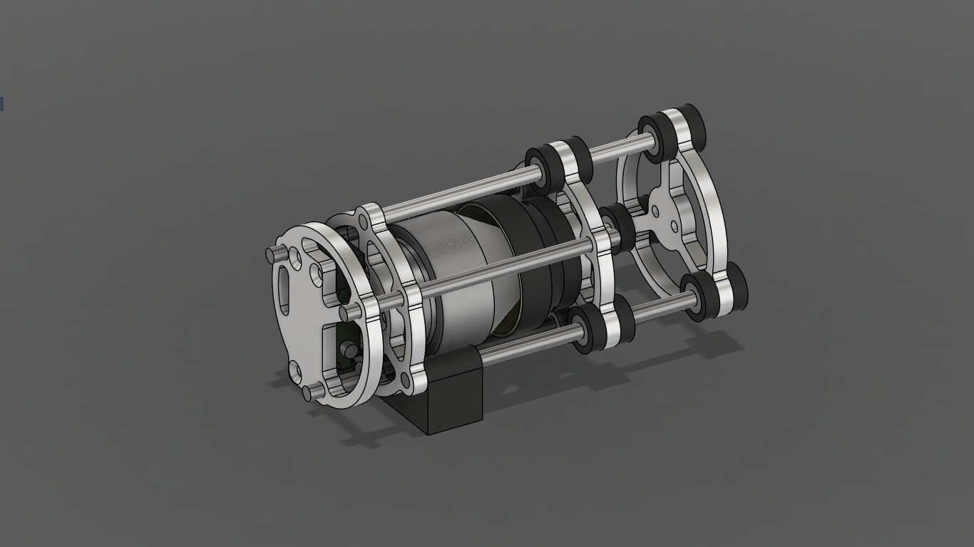
DesktopLauncher is very weapon oriented, with CAD work starting with several revisions of the flywheel module, before designing a robot around it. I started with something designed around the Overlander 2836, as I already have some of those lying around:

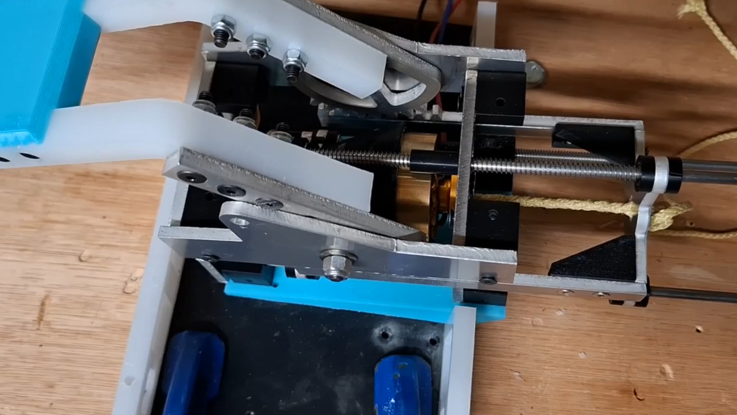
The flywheel in this version would have been made of mild steel and weighed around 100g. A Kingmax C507 acted as the trigger mechanism, pushing the leftmost plate away from the flywheel mounting plate. That plate is connected via threaded rods to the clutch carrier plate, which will then engage the flywheel. The intention with this mechanism was that it pulled on the twisted cord actuator, straightening it out (as I understand it, the straighter the twisted cord, the higer ratio reduction it starts out at). This version was discarded quite early on, as I felt that the throw on it was too small, and there wouldn’t be enough energy in the flywheel.

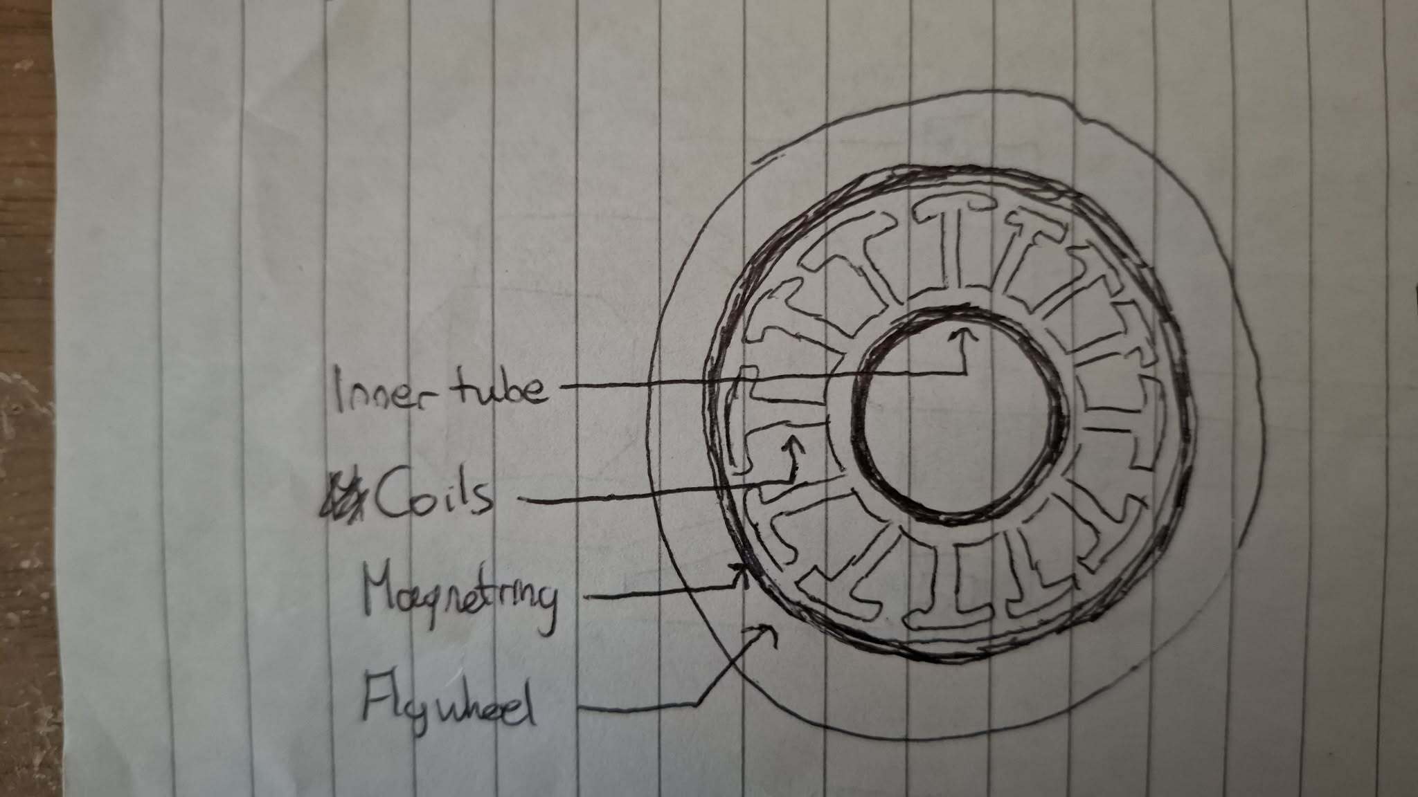
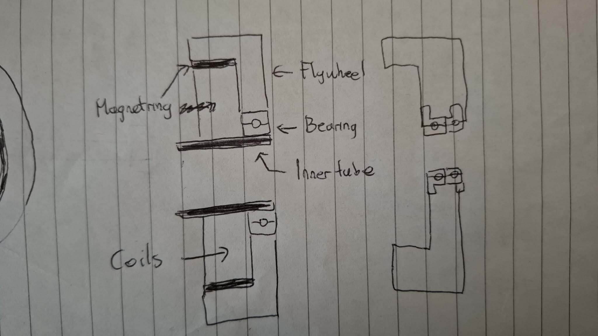
Back in January, I started tackling the problem again. I wanted to increase the available throw, which would mean a longer twisted cord, and to avoid a really long bot, I would have to do something like what Blip does, where the cord runs through the middle of the flywheel. Some paper doodling resulted in this:

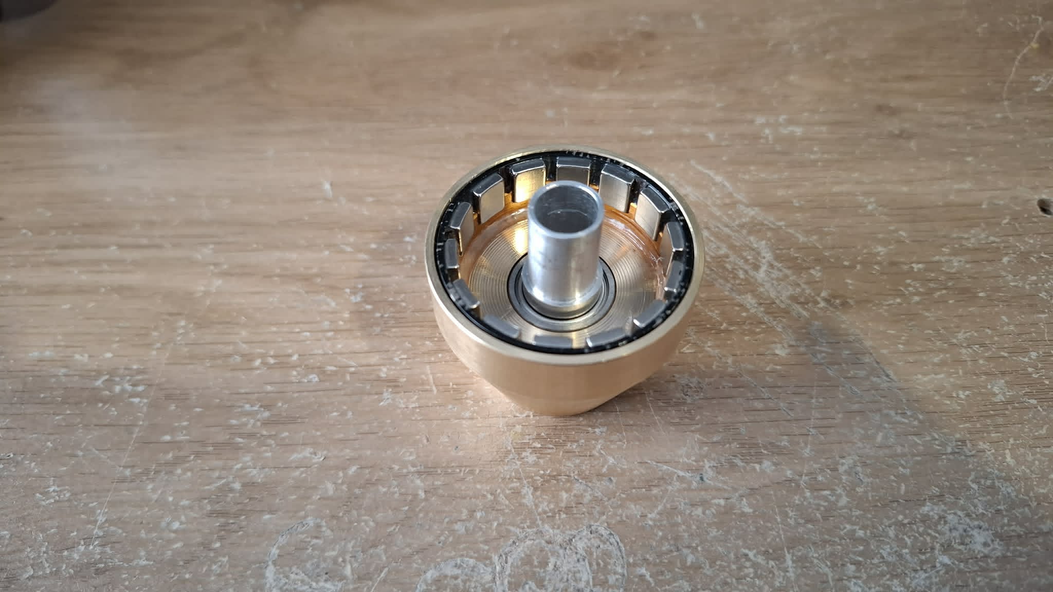
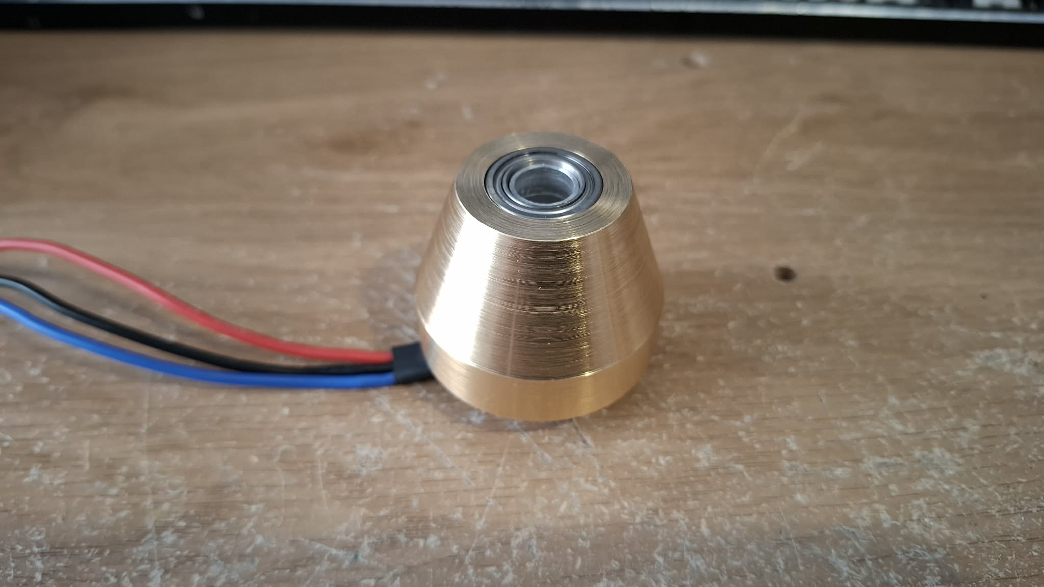
The idea was to find a large brushless motor, extract the stator wind from it, and refit a hollow shaft as the new stator mount. The magnet ring would get cut from the motor rotor, and pressed into a brass conical flywheel. I settled on basing this design around the DYS 4215.

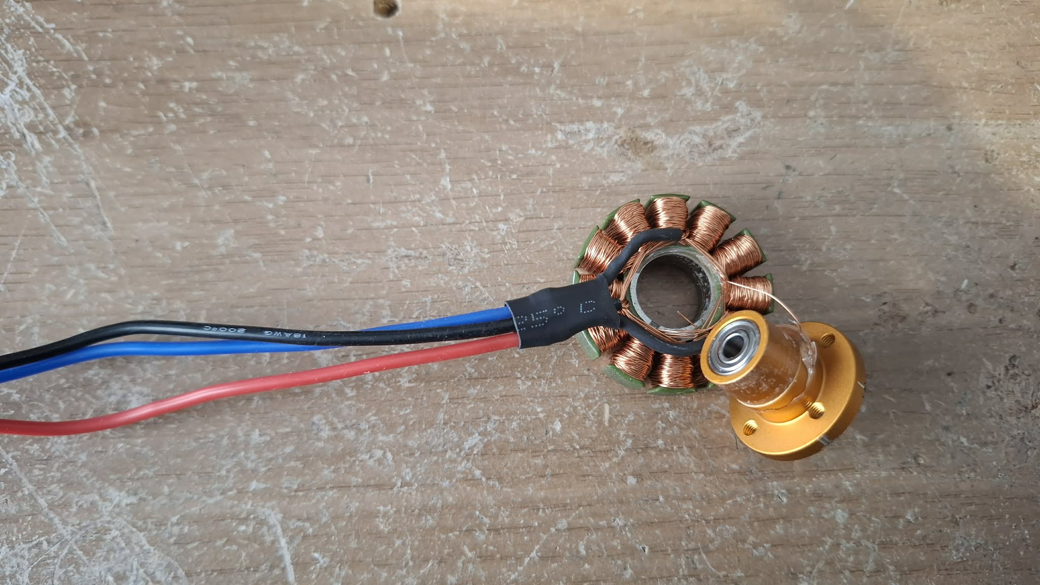
Attempt no. 1 - I attempted to press the mount out of the stator coils. This did work, however it turns out that some brushless motor manufacturers epoxy the wiring to the mount, so when I did this I also pulled some of the wires out. I then started to look into rewiring the coils, which did lead down a rabbit hole of unwinding the coil and counting the strands, measuring the wire gauge, and identifying the phase setup, but this all seemed too much effort.

Attempt no. 2 - I tried the same thing but used a heat gun in an attempt to soften the epoxy… all this did was cause the mount to expand, so it didn’t press out cleanly and I pringled the stator coil.

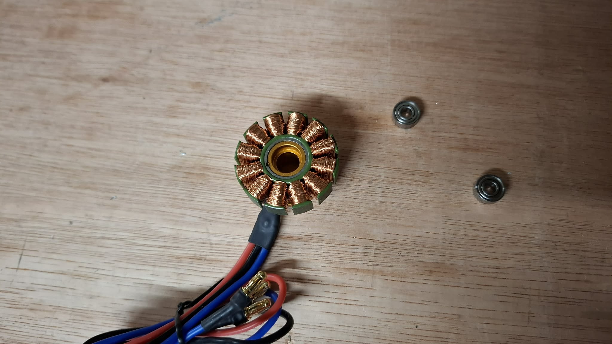
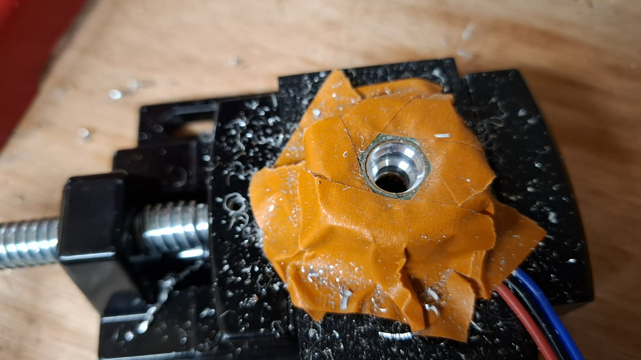
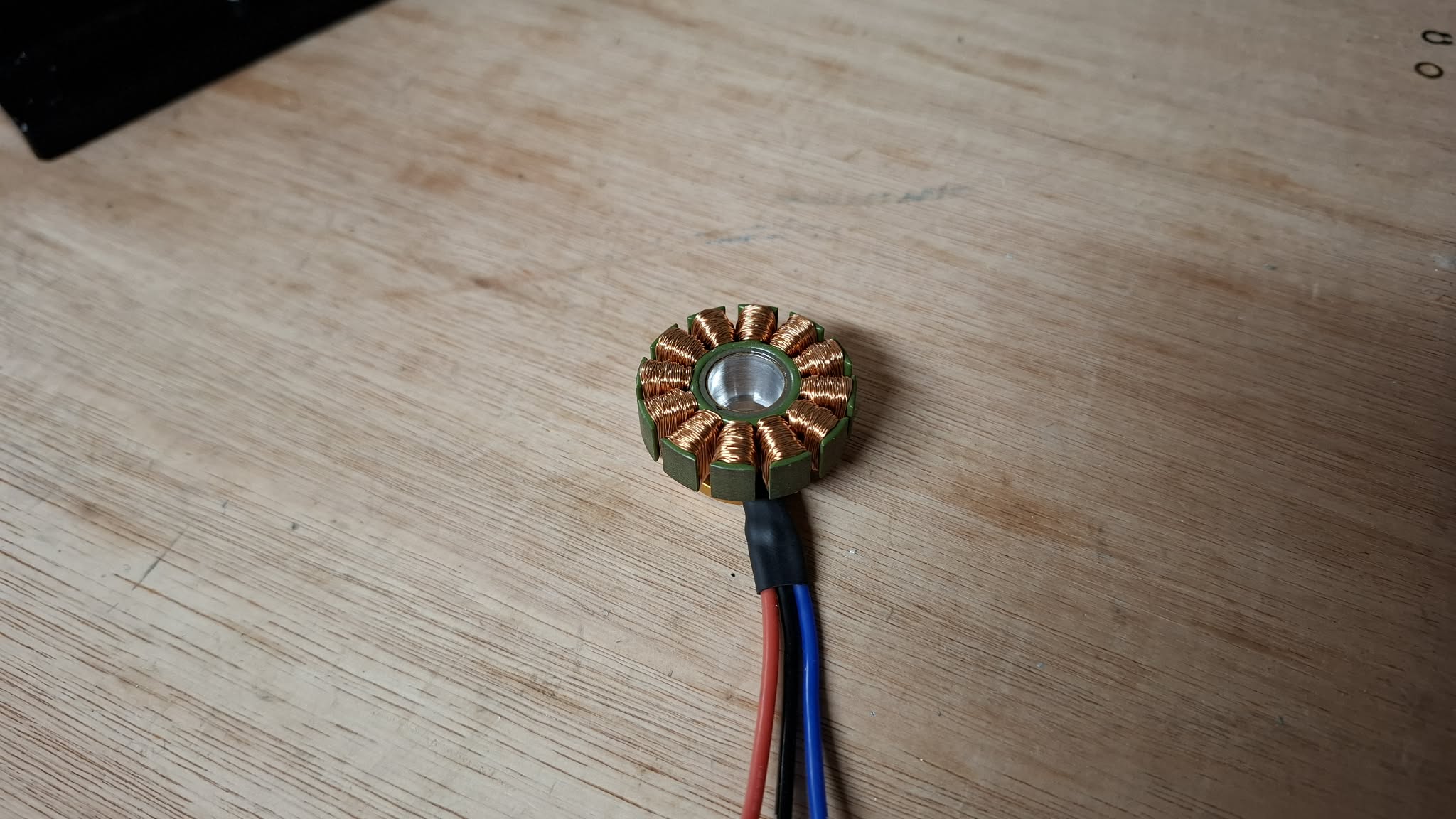
Third time’s the charm - I changed the plan. After a bit of research, I managed to press the bearings out of the mount (find a long screw smaller than the bearing ID, so you can wedge it against the back face of the bearing on the other side), then used a stepped drill bit to expand the resulting bore out from 8mm to 12mm, and then drilled the whole thing out to 12mm. This would then take a lathed hollow aluminium tube. this approach lets me reuse the existing mounting holes.

The flywheel in this version is brass, clocking in around 200g. A flanged bearing sits on either end of the flywheel to run on the hollow shaft. It and the hollow shaft were machined for me by Sam Price, thank you very much!

5 Likes

Holy shit that flywheel setup is beautiful :heart_eyes::heart_eyes::heart_eyes:

1 Like

When I first saw this, I thought to myself “Oh god Tom, what’re you doing this time?” But now that I’m seeing it being built up, I’m liking what I’m seeing, this is shaping up to be a monster.

2 Likes

Once I had a plan for the flywheel, I needed to design the flywheel module that would actually go into the bot.

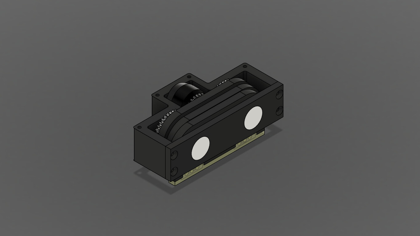
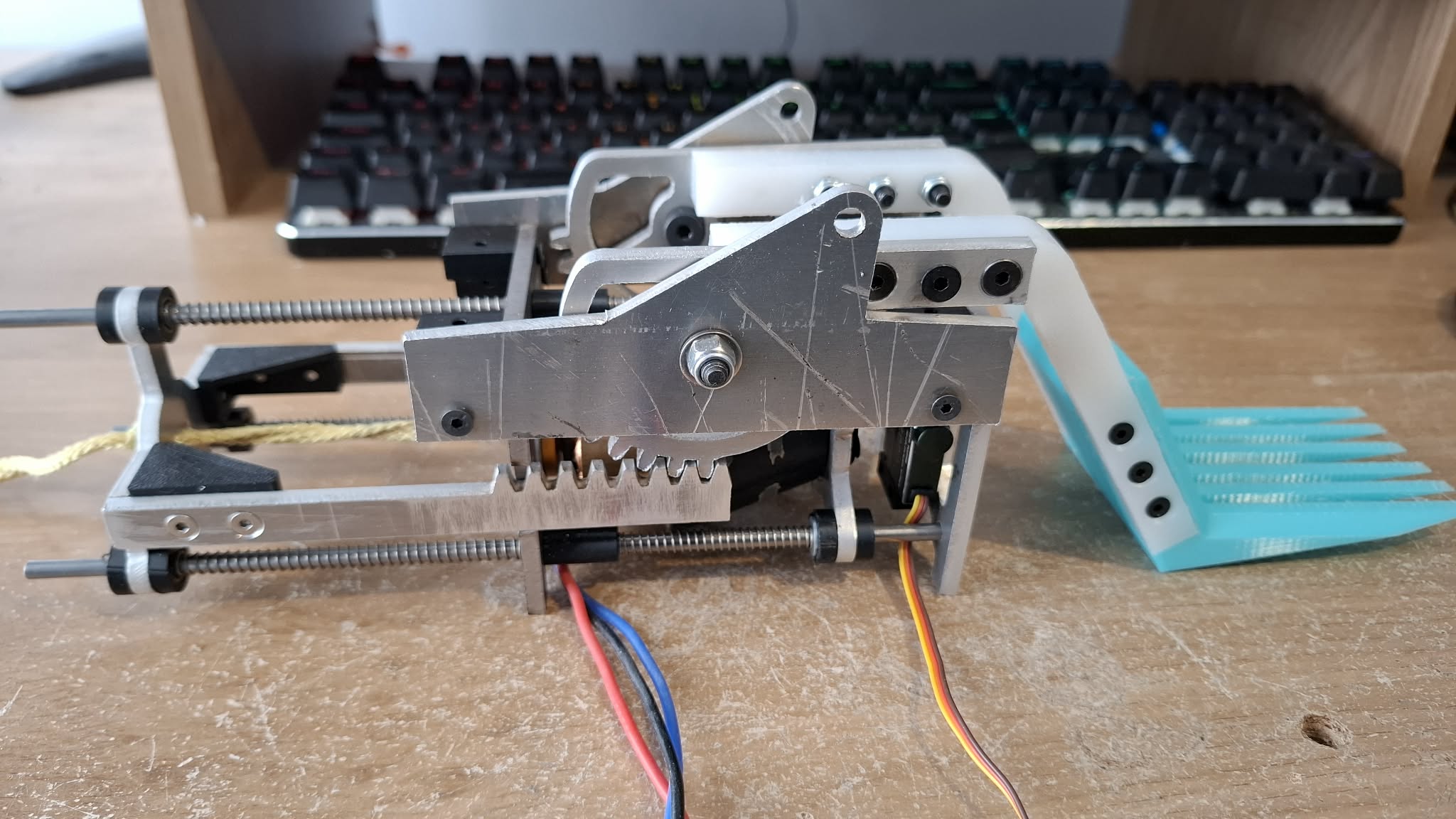
The module is fairly dense, but roughly what this consists of, from left to right is:

  • A plate to mount the trigger servo.
  • A plate for the servo to press against. This is needed because…
  • Clutch carrier plate. This has a large flanged bearing that the clutch sits in. The centre of the clutch has holes for the twisted cord to run through, so the plate mentioned above is necessary so there is something that is not rotating for the servo to push against. The carrier plate runs on some 4mm ID linear bearings, and compression springs around the steel rods return the clutch to the open position when the servo retracts.
  • Flywheel. The heart of the mechanism. This plate is hardox rather than aluminium, because I want to make sure it doesn’t bend or twist out of alignment, once there’s over 200g of spinning mass cantilevered on it.
  • Actuator plate. This connects to a rack and pinion to transfer the motion to the flipper itself. Similarly to the clutch, compression springs around the steel rods will return the plate to the closed position.

This module is pretty big, which I’m not happy about. As you can see from the full CAD, it means the module sitting in the robot juts out both up and out the back. I’m already planning on completely redoing the module after New Bloods to bring the height down as much as possible. There are also several issues I will get to when I talk about actually building the thing…

6 Likes

With the flywheel module designed, it was time to wrap a robot around it. For drive, I based the shuffler pods off of what I had done for Overclocked, so that meant dual cam shufflers driven by an Overlander 2826 1900kv motor. Unlike Overclocked, I flipped the orientation of the motor so that the drive gear would bolt directly to the can rather than attempt to mount a pinion to the shaft. This had a side effect of changing the reduction from 3:1 to 3:2, which increases the speed at the expense of stability, as I also opted for 3 legs of 7mm width as opposed to 4 legs of 4mm width.

Another major change from Overclocked is that now I’m double-supporting the drive axles, which are now + shaped printed axles, after speaking to some other shuffler builders. I can do this because now the drive pod is its own discrete module, which can just drop in to the robot. They are also ambidextrous, so my spares can fit either side.

As you can see, the drive motor is raised and not centred vertically - this is because I forgot to account for lasering tolerances, so I had to raise the motor by 8mm to get the mechanism spinning freely.

The white discs are also new - they are HDPE disks, which I found were necessary as in testing, I started to melt the axles against the TPU armour that wraps around the pod.

4 Likes

That is incredibly cool! I look forward to seeing it in action!

Out of curiosity, what mod are your gears? I know lasered do mod 1 gears fine, but it looks like you’ve managed to get them a fair bit smaller

Actually, they’re mod 1. I know people have gotten mod 1 lasered gears before and theyve been fine, so was unsure why it didn’t quite work for me until I moved the motor.

Assembly. i.e. integration hell.

In terms of fit, everything came together quite nicely. Lasered metal parts didn’t need much post-processing to accept all the screws and steel rods, HDPE and printed plastic all jigsawed together. The problems came from getting the flywheel mechanism working.

The frankensteined motor ran smoothly. The trigger servo, once endpoints were set up, engaged the clutch, and the return springs decoupled it from the flywheel. The rack and pinion setup for the flipper arm worked. However, in my haste to design the module (I had to get it sorted quite early on in order to meet a metal order deadline), I overlooked some critical parts of the setup.

For one thing, it is HEAVY. The whole module weighs over 900g fully assembled, which is a huge amount to spend of the budget even for a shuffler. I had to compromise on armour to even think about reaching weight.

The main issue, however, is I didn’t think about how the twisted cord would govern the function. When the clutch engages, it moves towards the end of the rack. The flywheel winds up the twisted cord, gradually actuating the flipper. Then I release the clutch, and nothing happens.

So yeah, the twisted cord is holding the clutch engaged due to the tension of it being twisted. This wasn’t an issue on the ant, as the clutch was fixed and I pushed the motor towards the clutch to engage it. However, I didn’t want to do this for DesktopLauncher as it would mean moving a siginificant spinning mass, and I was concerned about it flexing or bending the mounting due to gyroscopic forces. Unfortunately, with less than 2 weeks before New Bloods, I did not have the time to fully redesign the module and get parts fabricated.

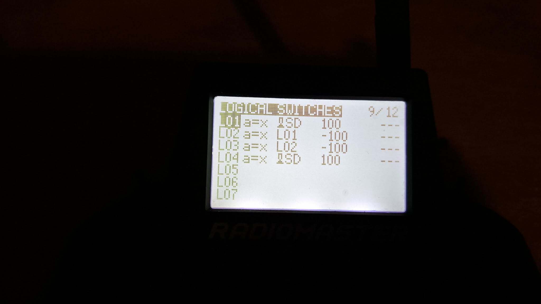
Eventually, I worked out that with some programming on the Zorro (thanks to Craig for your forum post about logical switches!), I could solve the problem.

Logical switch spam go!

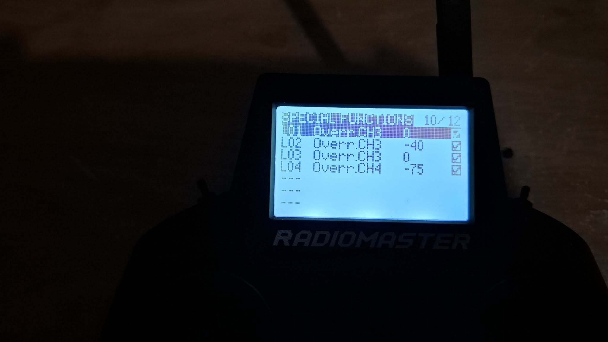
So, flywheel is on channel 3, clutch is on channel 4. When the right shoulder button is pressed, the clutch engages (L04) and the flywheel spins down (L01). The flywheel then runs in reverse (L02) while the clutch is still engaged, unwinding the twisted cord enough that the springs return the rack to its starting position. The flywheel then stops (L03) before the cltuch disengages so that it doesn’t start winding again before the clutch disengages.

4 Likes

Honestly open/edgeTX opens so many possibilities - I couldn’t go back to a less featureful TX myself.

Really cool that you were able to fix a potentially crippling issue with a handful of logical switches :ok_hand:

2 Likes

To pick up where I left off, with the issues mentioned previously now sorted, I could actually get round to a full systems test.

It did not disappoint!

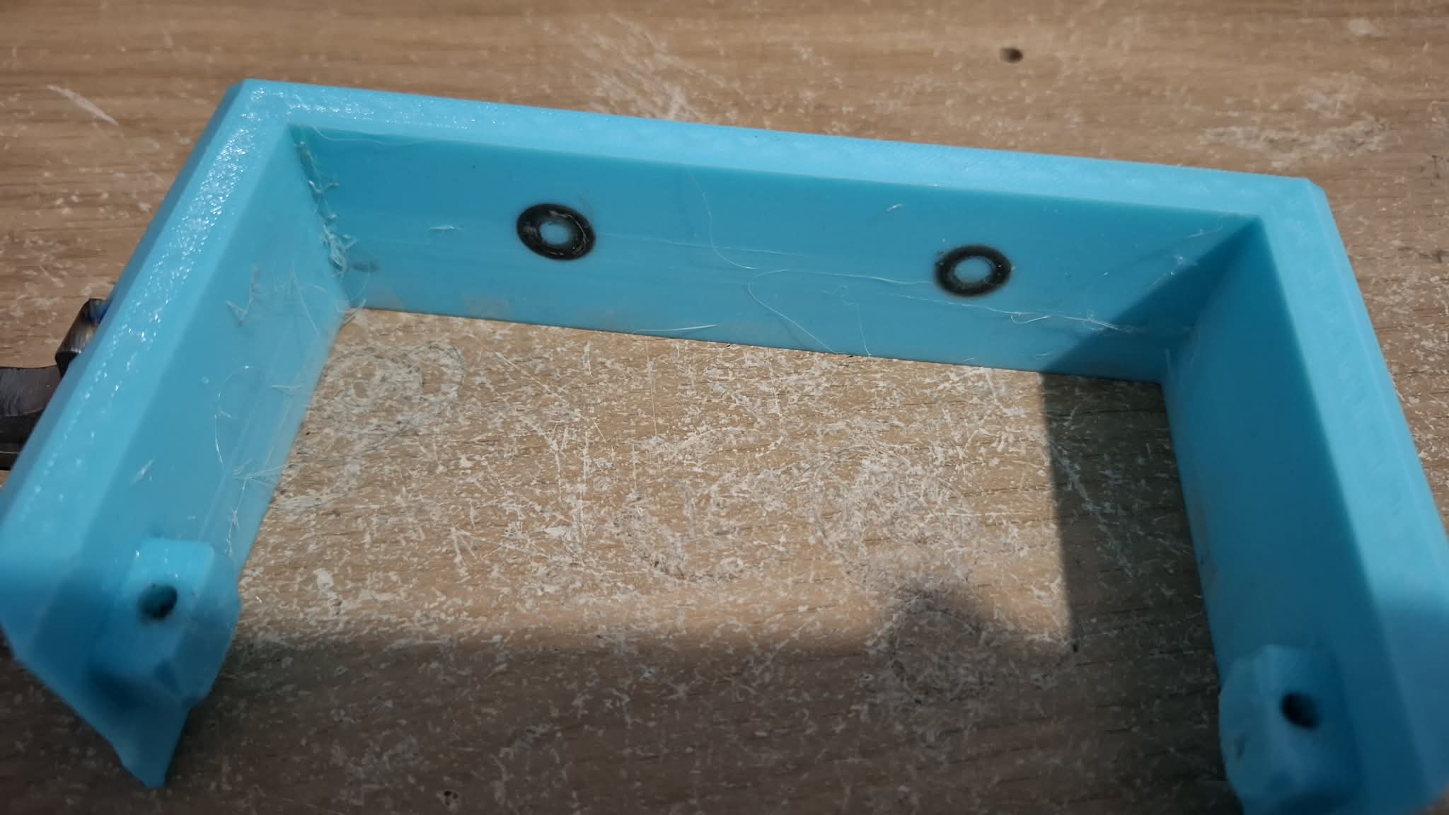
The rest of the buildup to the event was getting the bot ready, which mostly involved realising it was significantly overweight. You can see the CAD in the first post has fixed TPU forks and thin TPU side armour - this was a consequence of the overweightness with the original thick side armour and hardox forks lifted from PMXL.

Another weight-saving measure involved swapping the steel rods that all the sliding mechanisms in the flywheel module run on with carbon fibre rods, as well as cutting the top one short as I realised it was unnecessary for the sliding rack to run on it. This resulted in a reduction of the rear armour in its final form.

1 Like

The event itself. As always, a great time hosted by the BBB folks. 3 guaranteed fights with the first one being a 3-way fight.

Fight 1 was against Stingray, a 4WD undercutter, and P.I.T.A, a 2WD vert (check out their build log here). I was generally happy with this fight, as the flipper actually got to do its thing! I got one or two bigger flips and a handful of smaller ones. Despite the reset cycle programmed into the weapon, I found it didn’t reset all that reliably, and a few occasions where it seemed to trigger on impacts - I suspect impacts in the arena caused the clutch to partially close (it’s held open with springs), causing a bit of engagement with the flywheel. Stingray got stuck under the pit button about halfway through the fight, and not long after, DesktopLauncher stopped moving. It revived itself briefly before getting counted out, but shut down again, leading to P.I.T.A. getting the win with a few seconds left on the clock.

What followed was a huge repair job. I had to completely disassemble the flywheel module and realised that the wind plate had ripped itself out of the clutch, failing along layer lines. Lacking a spare clutch, the bodge fix was to drill out the existing holes so I could run longer screws through the remaining material, hoping it would survive the rest of the day (along with copious amounts of superglue).

Fight 2 was against another unique flipper, Moonshot, a compressor pneumatic flipper. Before the fight had event begun, I had lost one side of drive (this turned out to be an unplugged phase wire, I’m presuming I forgot to plug it in in my haste to get the bot ready for the fight!).Being unable to drive properly, I could not get the flipper into position to flip Moonshot, then the working drive side decided to grenade itself, leading to a K.O.

Luckily, I had a spare drive pod ready to swap in, so the turnaround this time was quick (my second fight had been swapped with Moonshot’s 3rd, due to how long it took for the repair, sorry!). Fight 3 was against Dark Eclipsor, a lifter/spinner a la Whiplash. Unfortunately, it was having issues after some big damage in its previous fights. The flipper in this fight was pretty weak for some reason, but I was vaguely more mobile, so managed to push around Dark Eclipsor for a bit before hitting the pit button, at which point DesktopLauncher stopped moving. Luckily, it came back, and I managed to push Dark Eclipsor into the pit.

So, good things - the flipper worked, at least in the first fight. While the drive was happy, it was moving quickly with a decent amount of pushing power. Things to improve - weapon reliability, drive reliability… wait that’s just the whole bot :stuck_out_tongue:

To expand a bit - the drive cutting out I’m pretty sure was due to thermal shutdown of the repeat DESC - the drive motors were VERY hot coming out of fights, to the point where I thought I had blistered my thumb when I brushed up against one retrieving it after a fight (luckily that didn’t happen). I think this is due to the change from a 3:1 to a 3:2 reduction meaning the motors were being pushed a lot harder. The plan for a future version is to move to a single cam design - this cuts the amount of bearings in each side and also lets the chassis hopefully become smaller due to the smaller drive pods. Also moving back to a higher reduction so the motors aren’t being pushed as hard.

For weapon module, I want to redesign it so it is a lower profile, and to change the clutch engagement so the motor is closing the clutch rather than the other way round, to avoid needing the programmed workaround. I did notice recently that Broken Link Robotics’ Loft, a 30lb flywheel flipper, recently showed off a reworked flywheel design with a horizontal flywheel setup, so I might try exploring something like that.
4 Likes