Eye, Robot (BW Cluster)

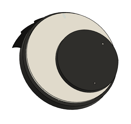
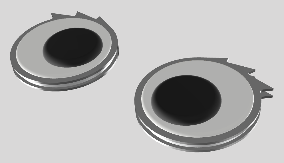
The most important side quest in any robot competition is, of course*, the googly eye game. There are lots of ways to play it, such as sheer number, hilarity of placement and so on, but for the purist, the only game is who has the biggest.

Well, if the googly eyes are the robot, you can only win:

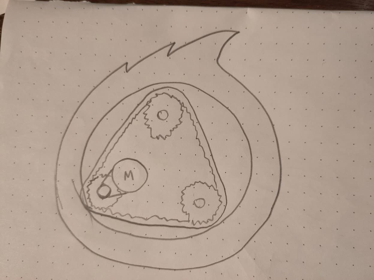
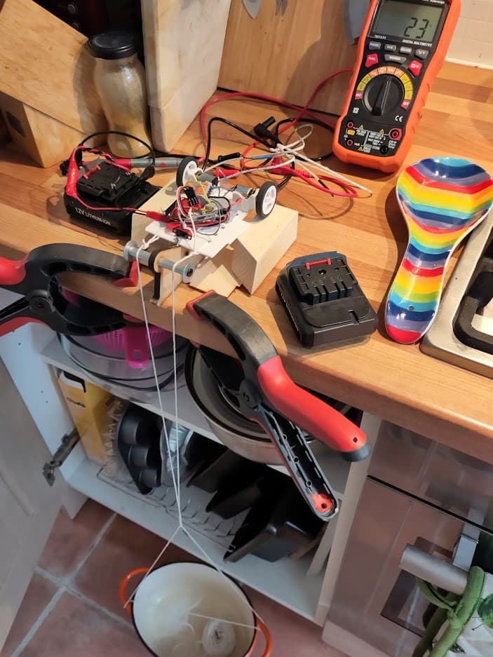
Currently this is just a well-pondered concept but I’m going to be building it in time for Subterranean Showdown, so it’s going to need to get a bit more real fairly imminently.

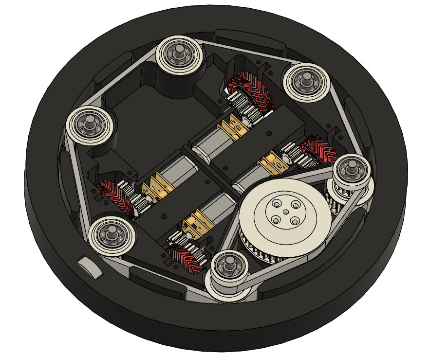
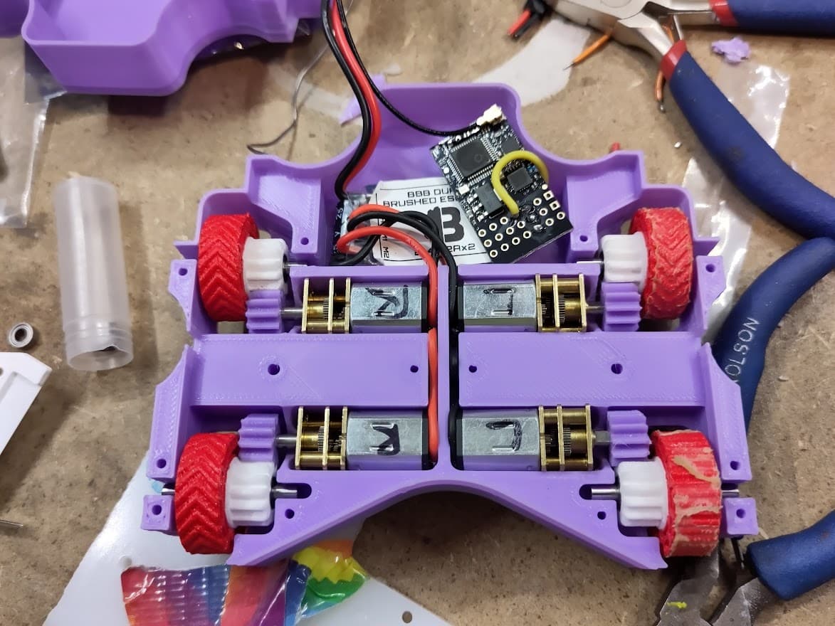
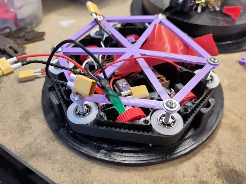
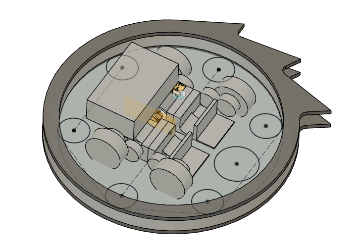
The basic idea is for two identical ring spinners, spinning in opposite directions and thus hopefully avoiding any friendly fire issues (since there should be no relative motion if they’re both spinning). The pupil of each eye is the directional indicator.

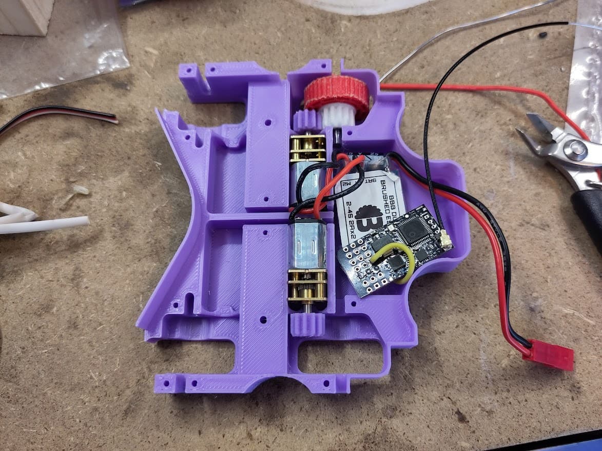
My main concerns at the moment are around motors, both drive and weapon. Standard beetle drives could work but it feels like they could be a bit too hefty. On the other hand there’s not much established in the “half a beetleweight” class. A few things I’m mulling over:

  • Smaller motor, something like this.
  • Standard beetle drive (probably brushed, don’t really want to drop that much cash on brushless for something that is just a bit of a laugh)
  • Use LOTS (probably 8 per bot) of N20s, at 12V (maybe even getting away with a dual ant ESC)

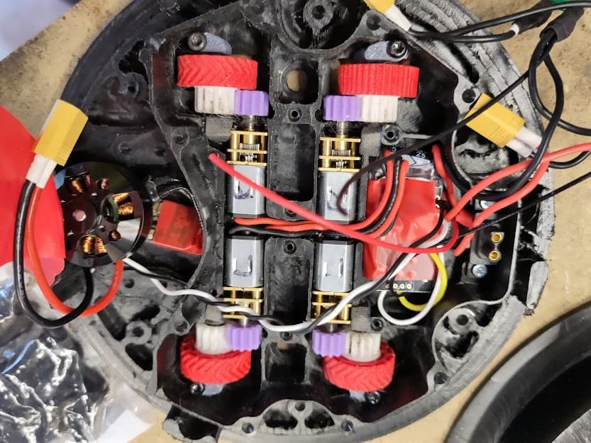
To drive the rings obviously no brushes will be permitted. I haven’t made a spinner before so while I have a reasonable theoretical grasp I don’t have the hands-on experience to draw on. Just from a weight/power perspective I was looking at something in the 2822 range (e.g., this) but not sure if that’s really in the right range (and I haven’t looked at the Kv numbers). I’m guessing with a ring spinner I’ll need to put a bit more weight into the weapon system and a bit less into the drive, so maybe something a tad larger would be appropriate.

That’s all for now, more detailed CAD should be on its way and do drop in with any thoughts! Cheers.

6 Likes

Love a good theme. Impressed with your commitment to it too! Will be keeping an eye (har har) on it to watch it develop.

While it’s admirable to use counter rotation to try an turn off friendly fire I will admit I can pretty sceptical as yo that working as minute variances in setup can yeiid a non trivial different in final RPM.

1 Like

Haha thanks!

That’s a fair point on the build-to-build variation. I’m also worried about the inevitable chaotic events where one hits the side of the arena (or possibly even the opponent?), stopping the weapon and also pinging it into the other one.

I guess the main thing is that contra-rotating disks are at least much better than having them both spin the same way where a typical hit would have a relative speed of 4-500 mph (also the eyebrows would look silly).

I’ve been mulling over some ideas for how to get power into the ring (and also guide them) and I came up with this:


(Isn’t there something about geniuses being able to draw freehand circles?)

The idea there is to have three timing pulley with a toothed belt sitting over them (with a tensioner, currently invisible). This is a close fit into the ring, with one (probably two) of the pulleys on springs. The non-toothed side is a multi-point friction drive into the ring; one of the pulleys is driven by the motor.

This would tick a few boxes (get power in, have some capacity for slip, impact absorbing, no direct mechanical link to the motor and gives the ring some support) but I do have visions of timing belt tagliatelle in there somewhere.

The other option would be the have an internal ring gear (I could maybe machine one from Delrin at the Hackspace) with a slightly shock-absorbing mounting but as soon as it moves the teeth are going to get mashed. Plus there was a maybe doing some heavy lifting in the last sentence.

Drive motor wise, you might want to look into 16mm planetary gearmotors. They’re quite common at the US Ant level. Might find a use for them!

1 Like

I love the concept. It’s brilliant.

I would certainly encourage more ring spinners, but sadly they are very technically challenging. I’d build one myself but my mechanical skills are poor.

As far as I can tell, the problems are that you need to support the ring without too much friction / resistance, but in a way which is robust enough to survive hits without breaking.

Also I’d suggest making the eyes different colours or the drivers are going to get confused.

1 Like

Late to the party - but this sounds super fun, definitely one to watch (pahaha) (sorry couldn’t resist!). Look forward to seeing (groan) this in August :slight_smile:

I agree with the other comment - take inspiration from Bowie and have different coloured eyes.

1 Like

@Hoppin - that was a good shout, although after a long google rabbit hole comparing Fingertech and Botkits I decided to try out some N20s based on some folk on Reddit claiming that they ran a 1lb ant with just 2 N20s (!). I MacGyvered myself a very janky dyno to find out (very approximately) what I could actually get out of a BBB N20:

This was almost completely inconclusive, but was enough to roughly confirm what the specs say they can do torque wise and more importantly to show they’ll run on 3s and pull a decent current for a couple of minutes without kersploding. Hence, after much deliberation I’m going to give 4x N20s on 3s (maybe even 4s with the throttle turned down) per cluster half, which is very light. Plus, with two robots and 360° attack it should be OK even if it’s a bit underpowered.

This is the current sketch of the insides:


I’ve put single stage gearing on the drive to protect the motors, but I’m now thinking that’s probably a waste of time, compared to just… having some spare motors. The six circles will be the bearings/pulleys for the ring and the slightly larger circle is the weapon motor. The battery is the biggest thing and will fit inside the “pupil” of the eye for protection.

@MarkR - thanks! I don’t have huge hopes for this working brilliantly at the first attempt but I’m just here for the theme really. As long as it drives and doesn’t catch fire I’ll be happy. I’m hoping that the multi-point contact from the belt will be a more effective friction drive and give a bit of padding, as well as running freely, but I guess we’ll see.
Good point on the eyes, although the chaos of having to stop the weapon to see which type of eyebrow is on which robot is appealing. I might make the safety LEDs different colours.

@TeamBee - harhar, thanks! I had thought of red and green originally but blue and brown (orange?) could look cool actually! Although now I’ve looked it up and it turns out David Bowie didn’t have different coloured eyes, he just had one permanently giant pupil… :exploding_head:

Never knew that! Everyday is a school day :slight_smile:

1 Like

Loving this theme and your plans so far!

N20s have been used on beetles a plenty in the past (full body spinner example with bearing support)

The gearboxes are probably the most likely failure point to give up so make sure you’ve got nice squishy wheels to give them a chance - I’d look at getting 12V N20s (BBB ones are 6V) just as the odds of burning them out on 3 / 4S is much lower

1 Like

Cheers Joe! That’s an impressive build on the end of that link. I’m interested in the weird toed-in wheels, seems like it’d fit in the space more easily and turn very well but maybe handle a bit weird? Possibly it makes it more stable accelerating/braking, not sure.

I was wondering about 6V vs 12V N20s. On the one hand going to 12V seems like the obvious thing to do, but I’m a bit wary of dubious quality N20s from ebay. They might not burn out but they also might not do much else, whereas I can be reasonably confident a BBB one will have some grunt even if it might not last as long. I did see on the shop that someone had been running them at 3s without killing them so far.

Squishy wheels sound like a plan - the alternative would be mounting the wheels with separate bearings and a soft(ish) coupling to the motor, but that might be too complicated.

Today’s update: ordered one of those Overlander 2822s and a Hobbywing 30A ESC - will have a play with these, hopefully they’re decent enough (they were pretty cheap so they must be good right).

N20’s should do you fine, especially if you have four on a 750g ronot not designed to push things. If you ever wanted some more power I remember Tim Bouwens used 13mm Maxon motors on Wajoo, which seemed a good compromise between an N20 and a more BW sized 22mm. I reckon you’d only be able to get away with using two for 4WD, but it would allow you to keep the form factor.

2 Likes

Cheers Eoin, good to have that in the back pocket. Looks like the N20s are up to the job so far though.

I had a bit of a 'mare last week trying to print test chassis out for proof of movement, and also to get all my wiring set up. By Thursday morning I had two warped prints of the key internal bits of chassis (all the stuff where the batteries and motors live, with the rest of the space bounded out). Then I was away for a delightful if temporally inconvenient weekend in the Lake District, from which I returned this afternoon.

First, because no-one likes suspense, here’s some successful movement:

The design has (necessarily) come on a bit since the last CAD update, I have settled on 4x 12V N20s (driving the wheels via some 3D printed gears, with the wheels themselves on dead axles), running on 4s (actually 2x GNB 450mAh 2s), with the Tornado Thumper 2822 outrunner driving a needlessly complex array of belts:

The spinner itself will be mostly UHMW with some Hardox teeth.

The view from outside hasn’t changed much:
image

First task for today was building up the wheels, which meant fitting the squidgy TPU tyres onto nylon hubs and getting some 3mm silver steel cut up, filed down, and pressed into some TEENY bearings. None of this was completely straightforward; the tyres, well, they certainly aren’t going to fall off, and it turns out 3mm silver steel is a pain to get into 3mm bore bearings. I had to tap them in with a hammer and a couple are already feeling graunchy.

They only cost a few pennies each though so I will get some spares and cross my fingers. I printed the wheels myself which is why they look like bogies, but the hubs are SLS nylon from 3D People (I have a bunch of stuff from them, basically all the pulleys and gears, worked out fairly cheap).

I didn’t make my life too easy for wiring but it could be worse:


This one was a bit trickier as it has a slightly larger Rx (the second one has the FrSky 4 channel from BBB). I do need to sort out the light, fuse and link yet but there’s a reasonable amount of space for that. I have a clear weekend next, and I’m hoping to get the chassis CNC’d this week (I have some UHMW billet raring to go), so hopefully more updates soon!

4 Likes

Looks good. Glad to see you took the time to add the all important googly eyes for PoM. :smiley:

1 Like

Weeeeell, unfortunately I didn’t manage to get this finished last week. A combination of hectic times at work and recalcitrant CNC router, coupled with some overoptimistic plans on my part, left me a bit short of parts by Saturday so I had to drop out of Sub Showdown as a competitor. :frowning: :frowning:

However, progress was made… CUE CNC TRAINING MONTAGE:


Top: First cut on the underside; terrible mess after roughing out the top; cutting a jig to locate when flipping over.
Bottom: Starting out the main chassis; nearly done; more than completely done, due to a gaping hole caused by a clamp coming loose…

This operation turned out to be a complete nightmare, because…

  • The toolpaths took ages. This is because, as you can see I removed essentially all the material (in fact 88% of it). This also caused at least one software crash.
  • There were a whole bunch of different tools and setups, which also took ages, including having to flip over and accurately relocate (which took ages). This is also very annoying when your part comes loose 3/4 of the way though a job.
  • I was really struggling to find a decent clamping strategy so the thinner bits of the base came out a bit wonky.

In retrospect, billet machining this was a daft thing to do. I had a serious case of Plan Continuation Bias here; when I saw these hat-shaped bits of UHMWHDPE (for sale at Robodojo for the princely sum of five Earth pounds each) I just thought they looked perfect for this build, and crucially failed to reassess my reaction. Anyway, you live and learn eh.

I finished working on this one piece at about 2345 on Friday night, which meant I still had to machine the second chassis body, plus machine a few other small bits and do some some last bits of wiring on Saturday maybe doable, but it felt challenging. After a rather poor night’s sleep I woke up and dropped a quick message to BBB, at least giving 24hrs to call in a reserve, then hit my jobs list. However, by the middle of the afternoon it was pretty clear I still had too much left to do and I had to drop out. At least that way I had some headspace for the last few hours to help Steve out finishing Forkhead, helping me feel slightly less useless…

Here’s all the bits I had (sorted into neat piles on Monday after getting home):


So close, but really, in retrospect so very far away.

Insides of the (mostly) finished bot:


I was quite pleased with how neat this turned out.

The real gubbins:


All fits in!

The Weird Belt Friction Drive Shenanigans:

I do feel like there are some potential (and indeed some likely) flaws in this design. I’m really not sure how well the friction drive was going to work, and I suspect that underlying concern contributed to slowing me down. On the plus side, one half of the cluster is close enough that it’s minimal effort to finish it, especially to finish it to a non-combat-ready state just to test the key ideas out. I’m going to avoid billet chassis machining for a while though…

2 Likes

Supreme effort, shame you had to pull but it’s probably a wise decision to save the heartbreak of having to fudge such a lovely machine at the 11th hour.

That is fantastically neat! I am envious of your parts organization too. At least there’s a lot of time to finish and test at your leisure now. Aiming for November?

With your friction system not being as you like, perhaps a positive drive could be an option. By which I mean a double sided timing belt or perhaps a printed belt like item with the tooth geometry but a more suitable friction-ey outer layer.

1 Like

Thanks Harry! Very much hoping to run them in November yeah. :slight_smile:

Last week I did a quick and dirty CAD & print of some bits to let me finish off building all the belt gubbins into the almost-complete half of the cluster. It went together reasonably well but the main belt was so tight it would hardly turn, and the extremely tight tolerances around the first stage drive meant it was binding up against the frame. The end result of which was that the motor couldn’t even turn when the belts were in place. Possibly there was some BL Heli shenanigans to be shenanigated to improve matters but there’s no way it could’ve been a viable spinning weapon.

Obviously that’s annoying but I am at least in the happy place of a decent prototype on which I can base a really sound design update. I’m in two minds about what to do with the friction drive side of things (I had looked at the double sided timing belt as it happens - definitely on the cards) but the main change I think will be to machine out a base plate and then use separate walls/aluminium standoffs/tubes/etc. rather than machining the whole thing from solid. At least the drive and electronics seem pretty solid, aside from maybe wanting to go a tad faster, and the size definitely works in terms of hitting weight and fitting stuff in.