For the three of you still awake and reading this, welcome back! It’s time for electronics deep dive part 2: firmware boogaloo. In this thread we stan Dennis Ritchie. Unlike Fatal Deviation’s PCB, I’ve been actively developing the code the whole time I’ve been competing with the bot, so I’m in a much better place to go into detail.
After the last big post the question of “why” is probably clear, but even in a robot with space for standard electronics I’d probably still build it this way. I like the flexibility and control of writing my own code, and it lets me do stuff that I simply can’t with off the shelf kit. I’m not a control freak I just have very specific requirements, I swear!
Background again: Beyond some basic university courses that I barely scraped through (and hated every minute of), I’m mostly self taught as a programmer. Mainly through google, (reading stackoverflow, API documentation etc) and reading and understanding Arduino examples and libraries as I learned the things I needed to solve problems I had (which is how I learn best). It didn’t come easy, as I didn’t have any more experienced colleagues to learn from, so I spent a lot of time banging my head against a wall or taking a frustration coffee break. In the puruit of learning to programme I wrote a lot of code that controls automated test equipment, and in those cases you really need to be sure there’s no bugs, because it’s really, really embarrassing if your test equipment glitches and blows up a very rare and expensive early prototype. Or if you burn the building down. I’ve done a little bit of one but never the other!
I’ve also written example code and libraries used by undergraduates and other junior engineers, so I had to ensure they could read and understand what was going on. I don’t claim to be an embedded software expert by any means, but as a result of this experience I’ve developed a programming style that’s somewhat akin to megablocks (I could never, ever claim to be as good as lego); modular but somewhat clunky and plodding. Feedback from my undergrads was good, but I had some influence on their grades, so they would say that…
TL;DR, I absolutely understand the struggle that is the jump from haphazard self taught programmer to more organised development. If this is something you’re actively interested in for your own robot but the complexity of the problem is overwhelming, hopefully there’s some tips and tricks here that can help demystify things a bit. I actually never thought I could do it either.
For this post I’m going to assume the reader has some existing programming knowledge - if you can mash together two Arduino sketches, or you’ve done an intro to Python course, that’s probably enough if you keep a tab open to google some stuff. I won’t be going into every single line of code; just going over the general layout and structure, and following the general data flow from pulling the trigger on the transmitter to seeing the robot move. All the code here (except library dependencies) is available to view in full on my github here if anyone wants to follow along at home in more detail.
The main programme is called bot_software.ino. If you’ve ever opened an Arduino sketch (or C/C++ project) it’ll all look fairly familiar. Headers and Libraries included at the top, then some objects declared to speak to various bits of hardware. Lower down are a few global data structures, and then the usual setup and (eventually) loop functions. There’s two of each though - the RP2040 has two cores, so you can run two things at once. It’s not really important in this context, even one core is more than fast enough.
You’ll probably notice three things. Firstly, virtually no comments. I’m of the school of thought that if your code needs comments, there’s almost certainly a more clear and readable way to write it. Screens aren’t 80 characters wide any more, so we can use descriptiveVariableNames in camelCase to make functions readable. I’m also heavily biased against nesting, so I get itchy whenever there’s more than three curly brackets open. This pays off when debugging because many small functions with clear inputs and outputs are easier to debug than one big one full of nested loops and logic. I don’t always claim to write good code, but I always try to write readable, maintainable code, and that’s almost the same thing.
The second is how short the main sketch is - under 300 lines. I try to keep the top level sketch as minimal as possible and handle as much of the clunky, bulky, hardware and platform specific stuff as possible in header files and classes. That way if I design a new revision of the board with different hardware I can simply change the internals of the class and leave the rest of the code the same. No more find and replace chaos, or chasing down function calls all throughout your code, just change a couple of lines in the class and the interface to the rest of the code stays the same.
The last thing is that all the standard Arduino loop does is a ts.execute() function. “ts” stands for Task Scheduler. A task scheduler is sort of like a really stripped down operating system that can only handle timing. A common trap for beginner programmers is the Arduino delay() function, which works great for a programme that only does one thing at a time, but is a real problem when you’re trying to do a bunch of stuff at once, since during the delay the processor does absolutely nothing. With a task scheduler you can break all your functions and routines up into small, easily interruptible chunks, and the task scheduler effortlessly juggles them like a jester with a bowl of fruit. If your function needs to pause for 300ms you break it into two functions and tell the scheduler to come back 300ms later. It’ll go away and use the time productively before coming back 300ms later to finish the job.
Getting an understanding of code written for a scheduler like this can be challenging, because there’s often no obvious starting point for the logic. In this case, the loop starts by checking for new data packets from the radio. This is done every single time the task scheduler loops for the shortest possible latency. While your typical FS2A receiver only updates the output signals every 44hz (I believe, it’s been a while since I used one), the FS-A8S ibus receiver I’m using has a 144hz update rate, so a new packet is received every 7ms.
void readRadioCB() {
  static uint32_t lastRadioTime;
  uint16_t chanData[IBUS_CHANNELS];

  iBus.loop();

  if (iBus.readChannels(chanData)) {
    lastRadioTime = millis();
    radioState = RADIO_OK;
    rxFrame = parseChannels(chanData);
    mainTask.restart();
  }

  if (millis() > (lastRadioTime + 100)) {
    lastRadioTime = millis();
    radioState = RADIO_DC;
    rxFrame = { 0 };
    mainTask.restart();
  }
}
iBus.loop() is a function inside a class I wrote* which will populate the chanData array if a new packet is received. If we’re all good, it tells the scheduler to queue the main task. If it’s been more than 100ms since the last packet then we go into failsafe, and all control inputs are zeroed before queuing the main task.
*I found some functions to decode the ibus packet on the internet, then wrote a class that lets you interface it with a standard Arduino serial interface and access it with a couple of non-blocking functions.
void mainTaskCB() {
  if (radioState == RADIO_DC) {
    rxFrame = { 0 };
    drive.setInputs(rxFrame);
    drive.doMaths();
    writePWM.restart();
  } else {
    inputHandler.restart();
    drive.setIMU(imuData);
    drive.setInputs(rxFrame);
    drive.doMaths();
    writePWM.restart();
  }

  Msg_t msg;
  sprintf(msg.txt, "S:%d T:%d FL:%d FR:%d GY:", rxFrame.steering, rxFrame.throttle, driveVals.FL.duty, driveVals.FR.duty);
  Serial.println(imuData.g.z);
  serialBuf.pushMsg(msg);
}
The main task then performs the drive mixing maths, either with actual IMU and input data if the radio is connected, or with zeroes if not, then queues the function that writes the drive values to the PWM controller/IO expander. If the radio is connected, the “input handler” is also queued, which actually just handles moving the weapon according to the toggle+button on the transmitter. Finally, some debug data is printed to the USB serial port. The serialBuf class I wrote is an extra serial buffer to keep messages ordered, because if you try to Serial.print() from two cores on the RP2040 at the same time all kinds of fun happens.
The drive maths and mixing is handled in src/drive.h. This contains another class I used to abstract the drive maths away from all the logic that makes the robot work. If you’ve ever been inside an Arduino library, drive.h will probably make some sense. There’s an initialiser, a begin function etc. There’s a lot of boilerplate maths or get/set methods, but there’s some interesting stuff too.
void BotDrive::setInputs(Radio_t inputs) {
  static uint32_t lastActiveTime;
  _steering = _deadZoneInput(inputs.steering, _deadZoneSteer);
  _throttle = _deadZoneInput(inputs.throttle, _deadZoneThrot);

  if ((_steering != 0) || (_throttle != 0)) {
    lastActiveTime = millis();
    _deadZoneSteer = _deadZoneMov;
    _driveState = MOVING;
  }

  if ((_steering == 0) && (_throttle == 0)) {
    _driveState = STATIONARY;
  }

  if (millis() > lastActiveTime + 2000) {
    _deadZoneSteer = _deadZoneStat;
    _driveState = IDLE;
  }
}
When the inputs from the radio are passed into the class, I’m able to perform dynamic deadzoning. That means I can have a large deadzone when the bot is stationary and avoid it making angry PWM noises or creeping, but almost zero deadzone while driving to avoid the notchy feel around the centre that a fat deadzone can cause.
uint32_t BotDrive::doMaths() {
  uint32_t startTime = micros();

  int16_t t = _throttle;
  int16_t s = _steering;

  if (_enableExpThrot) t = _expFunction(t, 2);

  if (_driveState == IDLE) {
    _driveData.FL.coast = true;
    _driveData.FR.coast = true;
    _driveData.RL.coast = true;
    _driveData.RR.coast = true;
  } else {
    float pidOutRads;

    switch (_driveMode) {
      case TANK_OPENLOOP:
        _driveData = _tankDrive(t, s);
        break;
      case TANK_CLOSEDLOOP:
        pidOutRads = _runPID(_steerToRads(s));
        if (_enablePID && (_driveState == MOVING)) s = _radsToSteer(pidOutRads);

        _driveData = _tankDrive(t, s);
        break;
      case COMPUTE:
        _driveData = _tankDrive(t, s);  //bronk
        break;
    }
  }

  return startTime - micros();
}
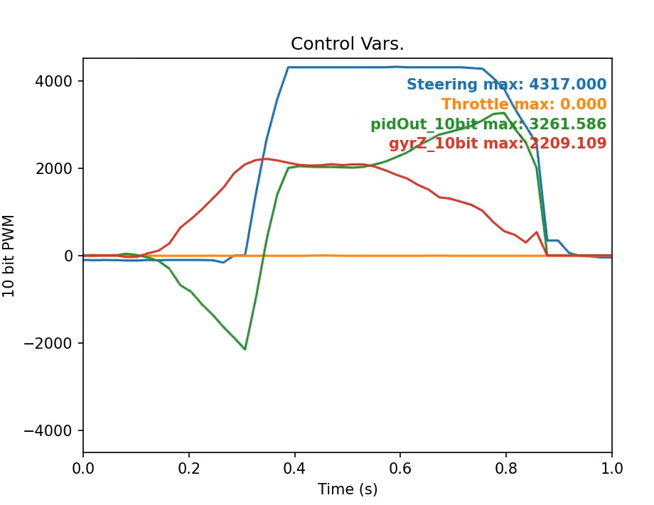
This is the main maths function called from the main task in the top level of the sketch. It performs an exponential adjustment on the throttle (I could do this in the transmitter too, and I do use 30% expo on the steering channel, but I like the feel of the plain X^2 curve on the throttle), then checks the state of the drive. If it’s idle (>2s since the last control input) it disables the motor drivers (called “coast” here because when they’re enabled but idle they’re braking by default). Otherwise it selects a drive algorithm. The default is basic arithmetic tank drive mixing with gyro assist. Because the steering input is mapped to +/-4095 (4095 == 100% for the PWM controller) there’s some juggling back and forth between PWM and rad/s at times. I decided that 100% on the steering input is 30rad/s, which I measured by plugging the robot in with a really long USB cable and doing skids while watching a laptop screen and trying not to let the robot eat the cable.
The gyro assist is performed via PID controller. There are better explanations out there for the maths behind PID loops than I could ever manage, but the TL;DR for a PID controller is that it will take an input measurement, then perform some calculations according to the P, I (and sometimes) D parameters to vary an output to try meet a requested target. Usually you have to tune those parameters (sometimes a lot) to balance the responsiveness of the system against oscillation or overshoot, but once it’s properly tuned it’s an extremely useful system. As well as other electromechanical systems like hoverboards and segways you’ll find them on ovens, allowing stable-ish temperature control with an element that only switches on and off only every few minutes, and on lifts - ever notice the lift slow down to a crawl when it reaches your floor and creeps until it’s level with the doors? That’s the PID loop kicking in to line the floors up properly. Fun fact, apparently lift systems are some of the only ones where you’ll find a considerable amount of D. Quiet in the cheap seats.
The way I use the PID controller here is by taking the angular momentum (rotational speed around the Z axis) measured from the IMU as an input and the angular momentum requested from the steering input as a target. The PID controller will do some maths in the background and return an output value that tries to return the measured value to the target value. If an external force like a slipping wheel, or a fork hanging up on a floor seam applies a rotational force to the robot in one direction, the PID will automatically compensate in the opposite direction. This can be best seen when driving on a really low traction surface like dusty polished concrete. Whether stationary and turning on the spot or going full speed, the robot will rotate around its Z axis at exactly the same rate. The moment you centre the wheel, the robot will attempt to continue on in the direction it’s currently facing with an angular momentum of zero (i.e. a dead straight line).
I’ve played with the tuning parameters a fair amount but P = 1 just seems about right. This means the PID controller isn’t actually necessary - since all I do is run it with a P value and no I or D I could just use a far simpler proportional only controller, but it works and maybe one day I’ll want to add some integral for tuning purposes.
Drive_t BotDrive::_tankDrive(int16_t t, int16_t s) {
  Drive_t out;

  if (t > 0) {
    out.FL.duty = -s + t;
    out.FR.duty = s + t;

    out.FL.duty = constrain(out.FL.duty, -MAX_PWM, MAX_PWM);
    out.FR.duty = constrain(out.FR.duty, -MAX_PWM, MAX_PWM);

    if (out.FL.duty < 0) out.FL.duty = 0;
    else if (out.FL.duty <= (MAX_PWM / 8) && (out.FR.duty > MAX_PWM / 2)) {
      out.RL.duty = out.FR.duty / 8;
    } else {
      out.RL = out.FL;
    }

    if (out.FR.duty < 0) out.FR.duty = 0;
    else if (out.FR.duty <= (MAX_PWM / 8) && (out.FL.duty > MAX_PWM / 2)) {
      out.RR.duty = out.RL.duty / 8;
    } else {
      out.RR = out.FR;
    }

  } else {
    out = _notForward(t, s);
  }

  return out;
}
I split the control mixing that actually decides how much power each wheel receives into two parts - forward, and notForward. This lets me mess with weird control schemes only in the forward direction and just reuse the same basic mix in reverse. Turns out the ideal forward mix so far is pretty basic - I just add the steering and throttle together as you might on a transmitter mix. There’s a bit of conditional stuff where I clamp negative values to zero, and give the inside rear tyre a little bit of power on tight turns to reduce the wheel scrubbing that causes the rear of the robot to noisily wheel hop sometimes. The finished output values for each wheel are stored and then retrieved by the PWM controller task in the main sketch, which tickles the relevant motor controller pins as appropriate.
I have done a lot of experimentation with things like wheel path calculation and tracking but it always seems to work less well than some variant of just adding the steering and throttle values together arithmetically. I think I need more sensors for more complicated drive maths - a laser gaming mouse sensor for ground speed sensing and wheel encoders for wheel slip sensing would unlock full active torque vectoring, traction control, and ABS…
Believe it or not, that’s actually all the main, interesting functionality in the robot. I thought I’d be writing more than that, but while there’s a lot of lines of code total, the majority of it is just wrapping up an Adafruit library, or is the kind of thing I’ve pulled from example code, or is general routine stuff; doing things like reading the battery voltage from an analogue pin, or controlling the RGB, or grabbing data from the IMU via i2c all just becomes background noise after a while, which is why abstracting it away into a class is so helpful when you need to focus on writing code that isn’t spaghetti.
While I’ll be the first to admit my solution is pretty extra, I think there’s a lot of utility in something simpler like an Arduino Nano wrapped in heatshrink; used for advanced control mixing your transmitter might not be able to handle, or to trigger canned movements on multiple servo channels with a single transmitter switch, or deadbug an IMU module to the back to detect which way up the robot is driving and invert the controls.
You’ve probably already seen the big honking downside to building a robot like this - with designing PCBs and writing code on top of all the usual electrical and mechanical design stuff it’s essentially three times the effort involved. I can at least re-use the boards and/or software in other robots. That’s what I tell myself anyway.
I actually trimmed my beard (the source of my power) the other day so now I’m a bit lost and not sure how to end this post, but if you got to the end, congratulations. Like the previous big post, I hope that by putting this out there the scope of the whole “robot with an Arduino in it” thing is a bit better understood. As with before, feel free to reply or PM if you have any questions or think something needs clarification.