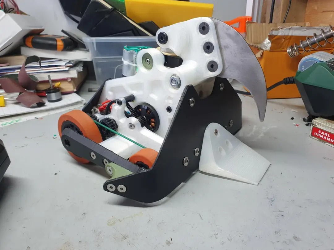
Work continued at a relatively stable pace as I nipped (har har) away at a lot of the little jobs.
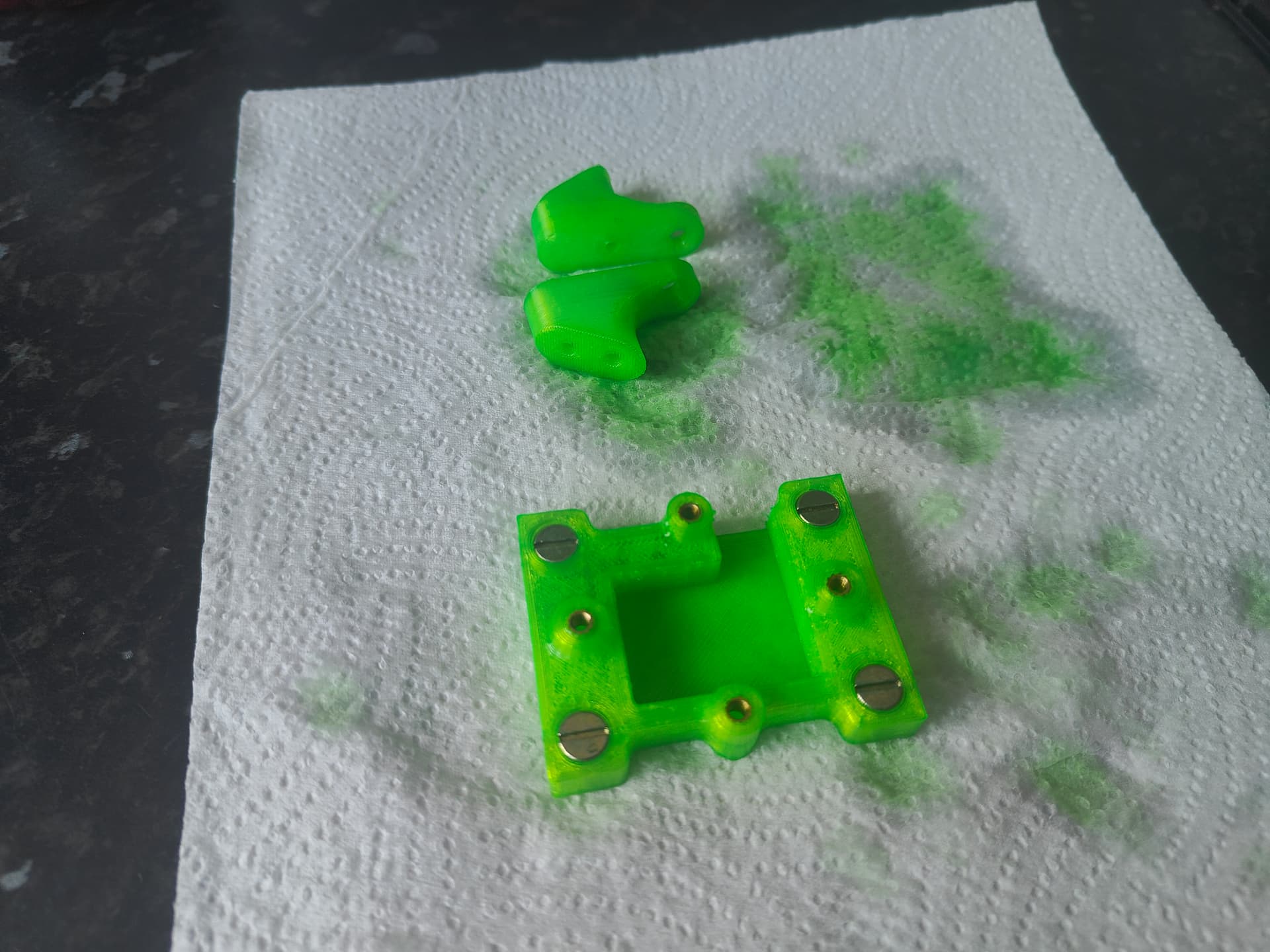
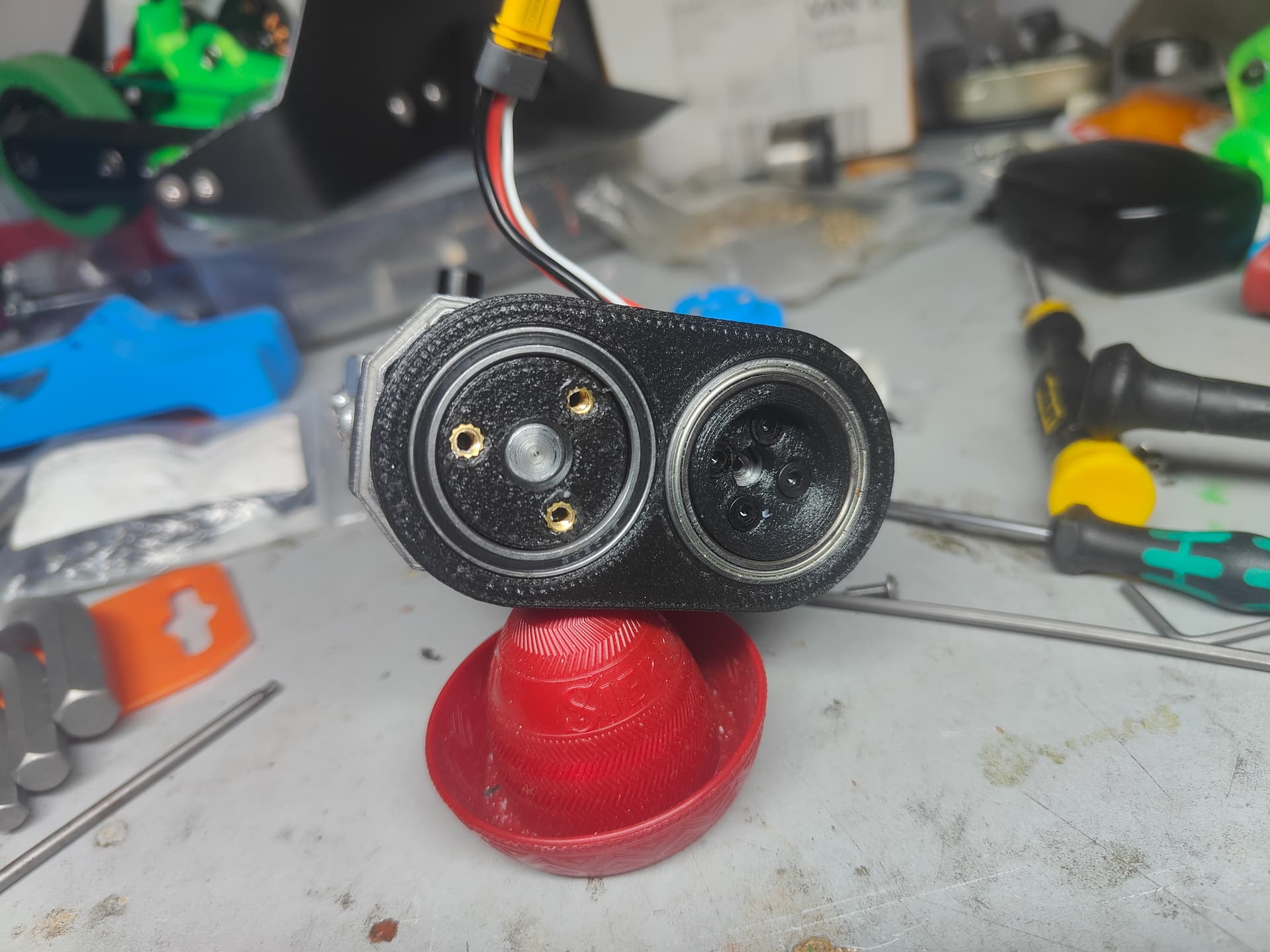
The ESC mount and little side connectors got the standard dye job to spice up the colour palette.
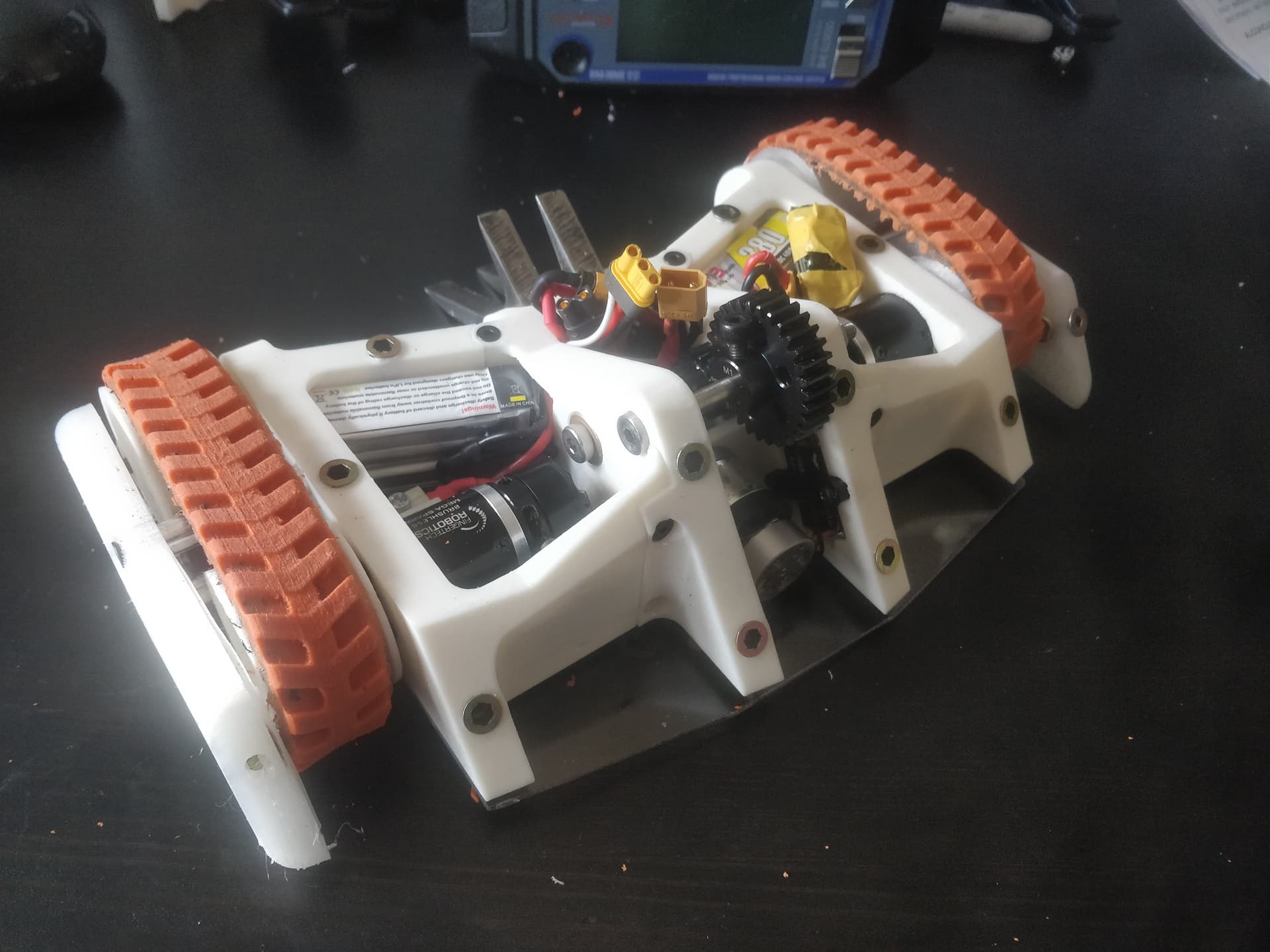
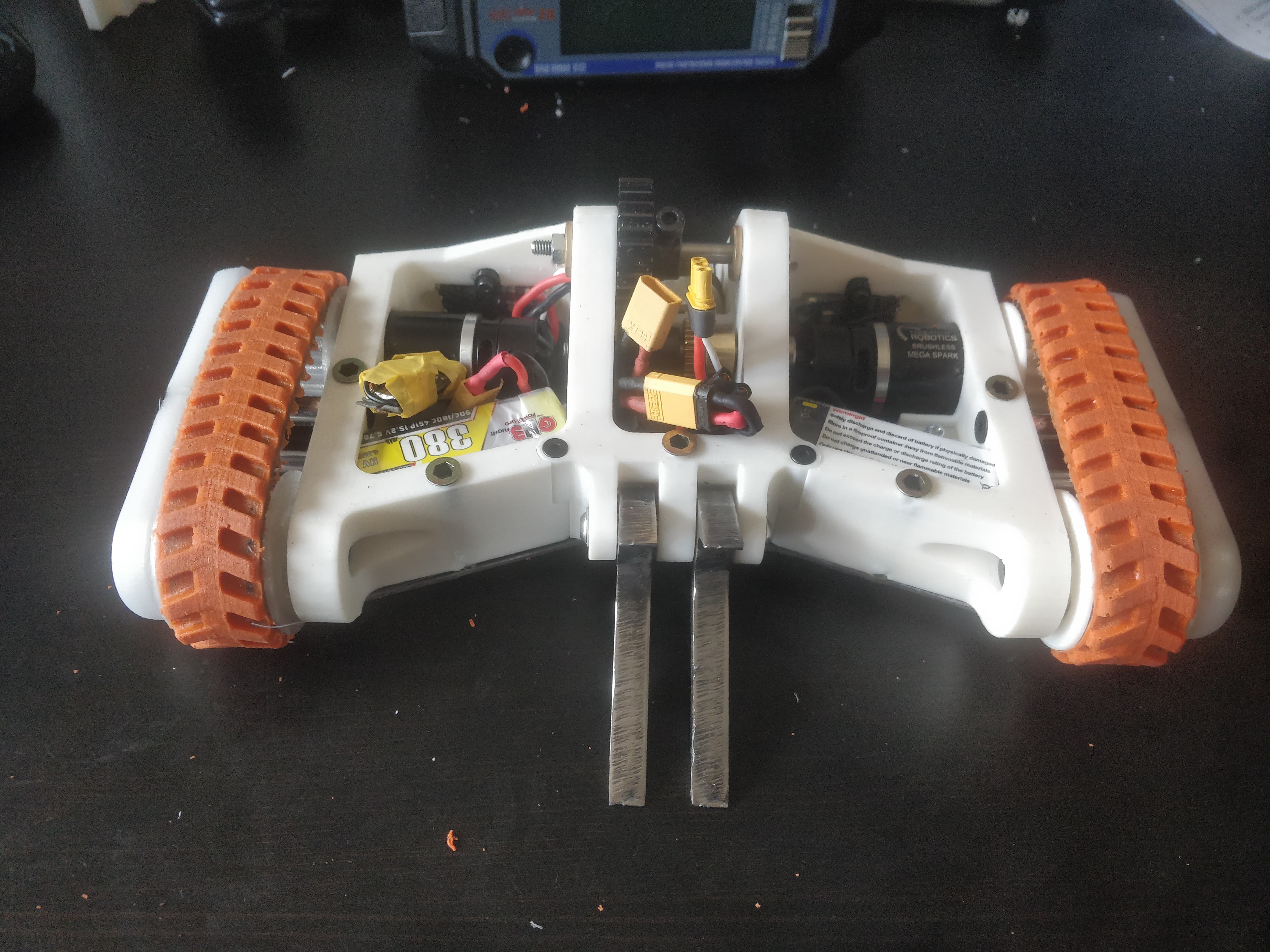
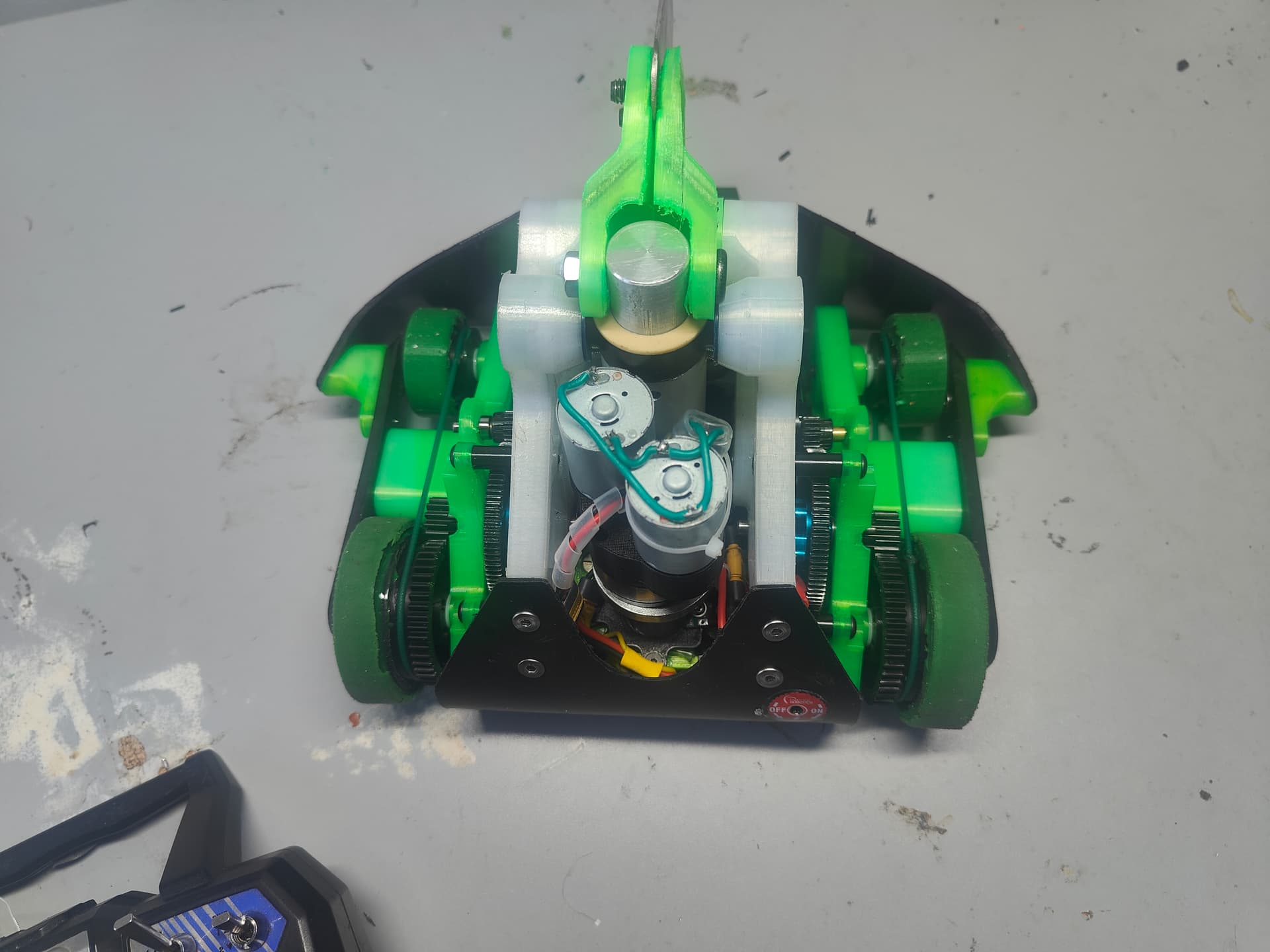
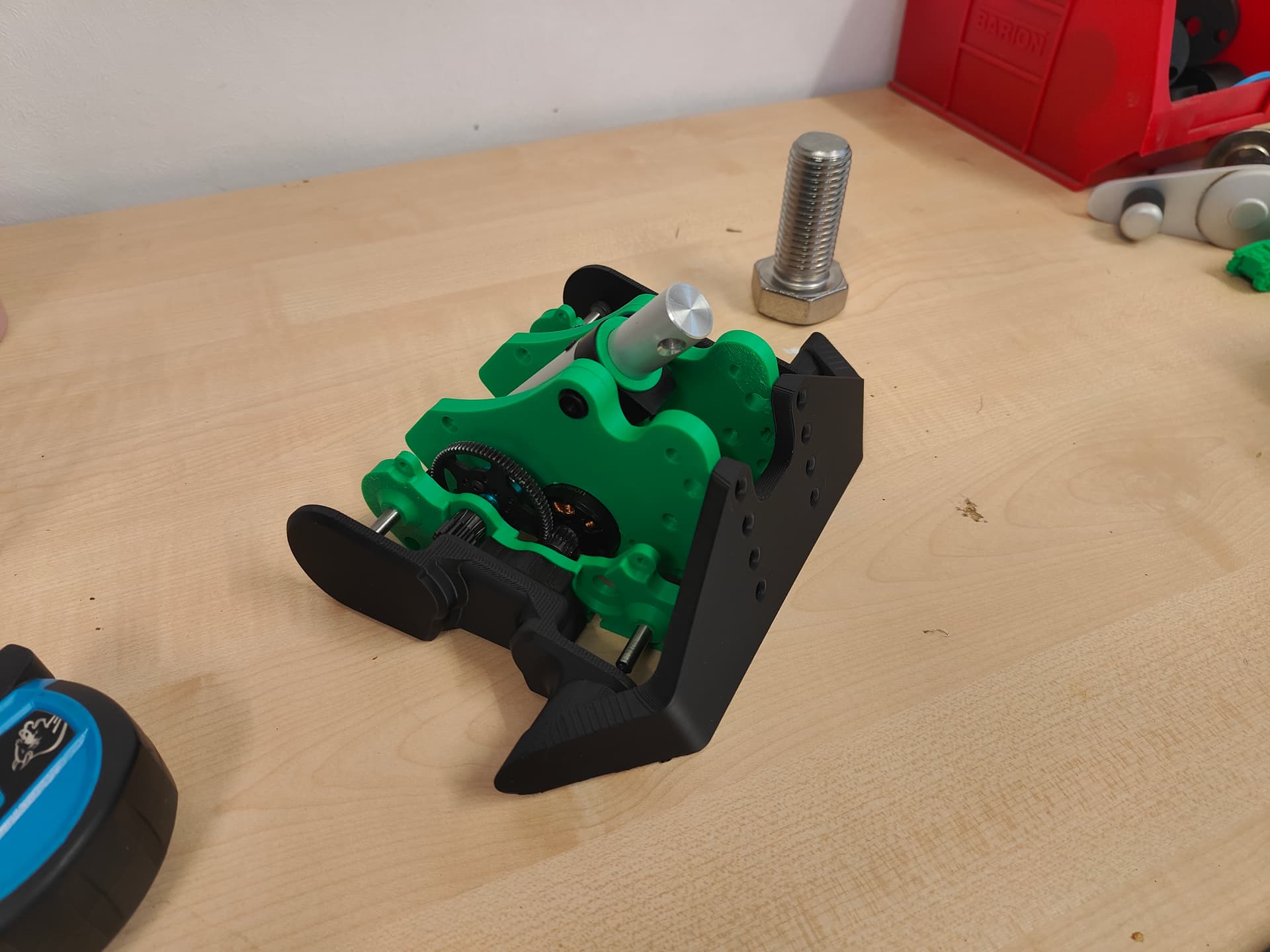
It was pretty well on the way at this point - some might even say finished. They would be dead wrong as I had plenty more buggering about to perform but this was functionally complete enough to make this video: https://youtu.be/zDk7lApIbPQ?si=oku6sWsLCghTGUEr
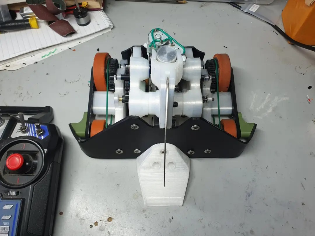
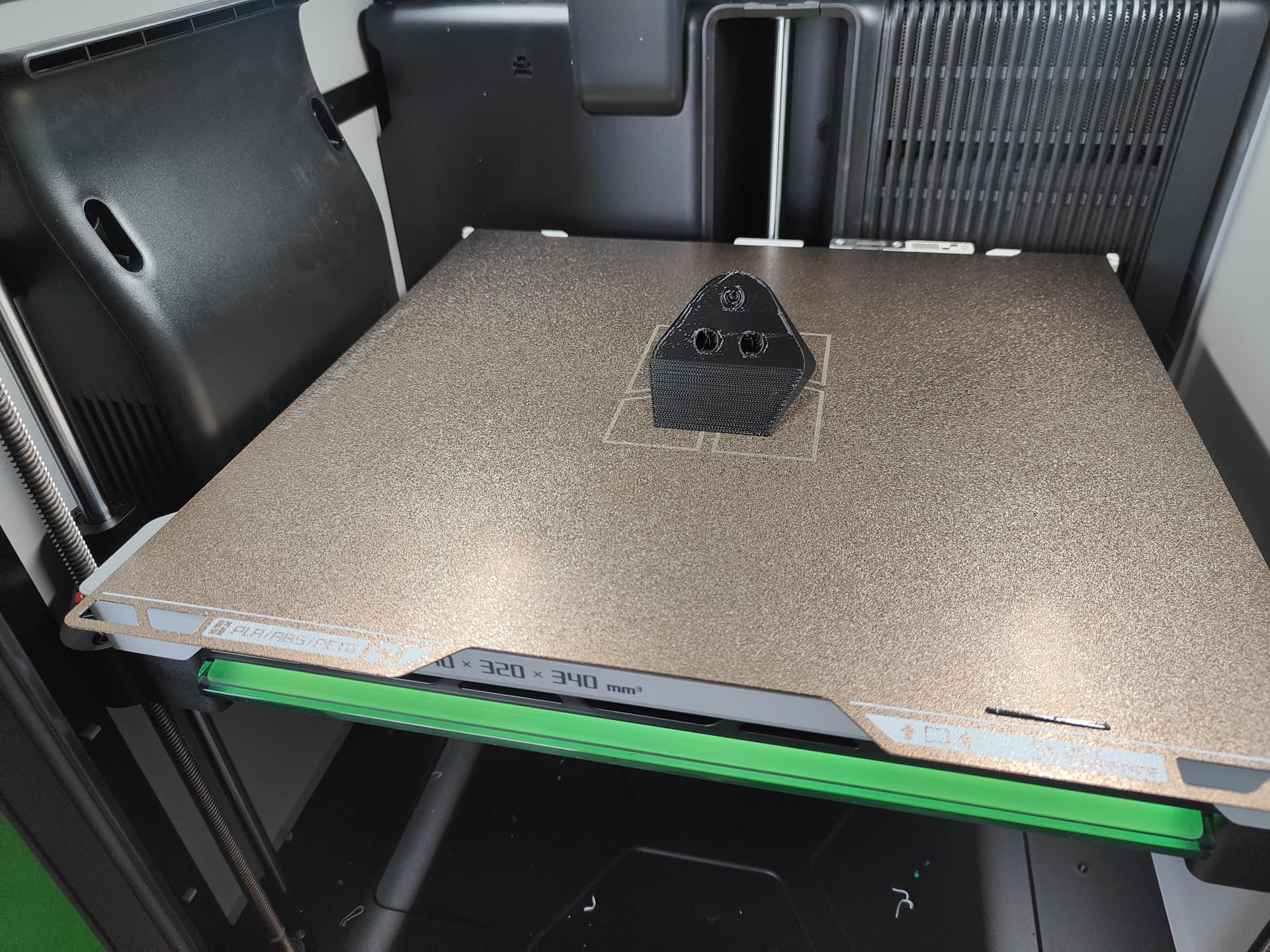
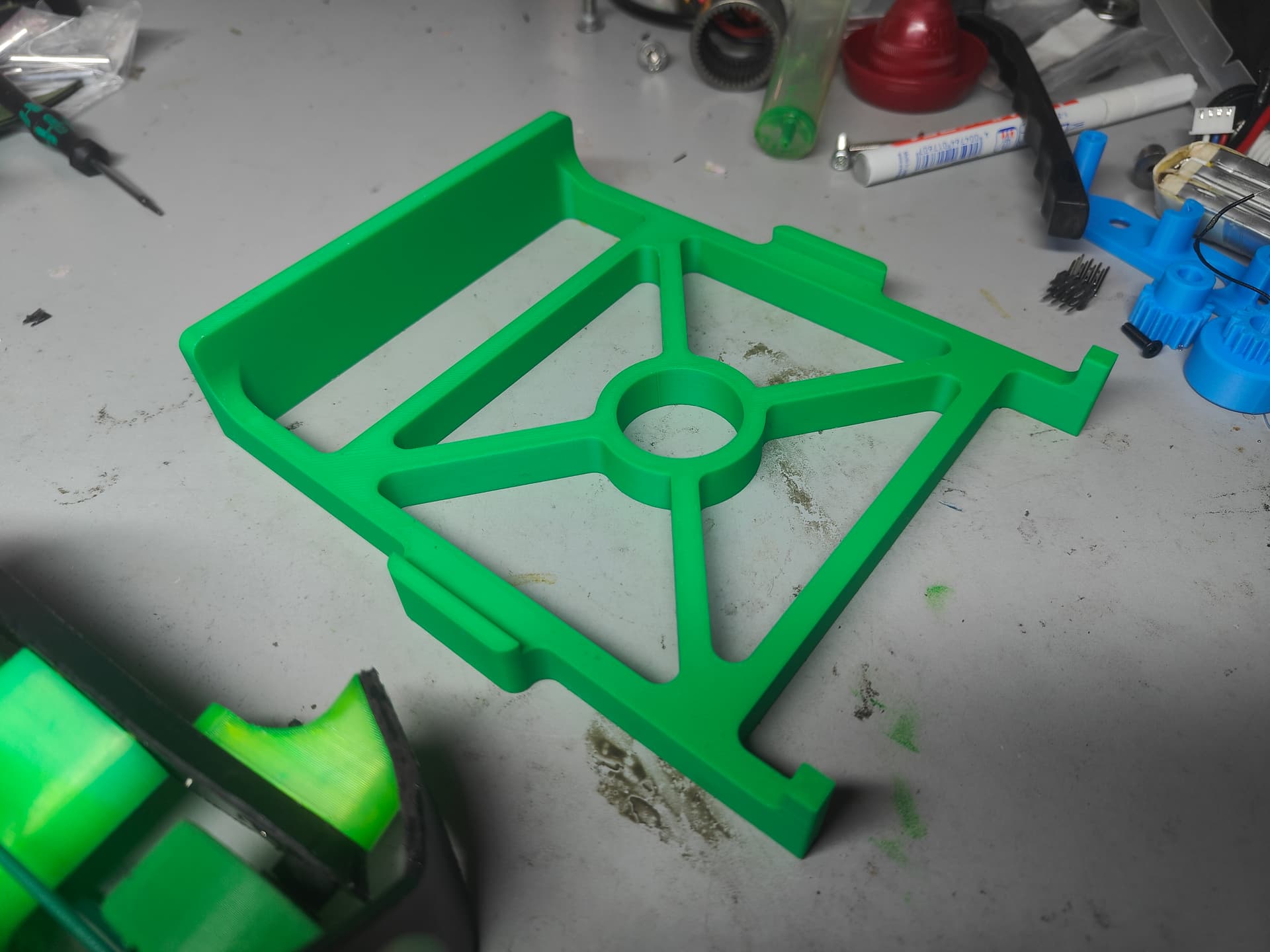
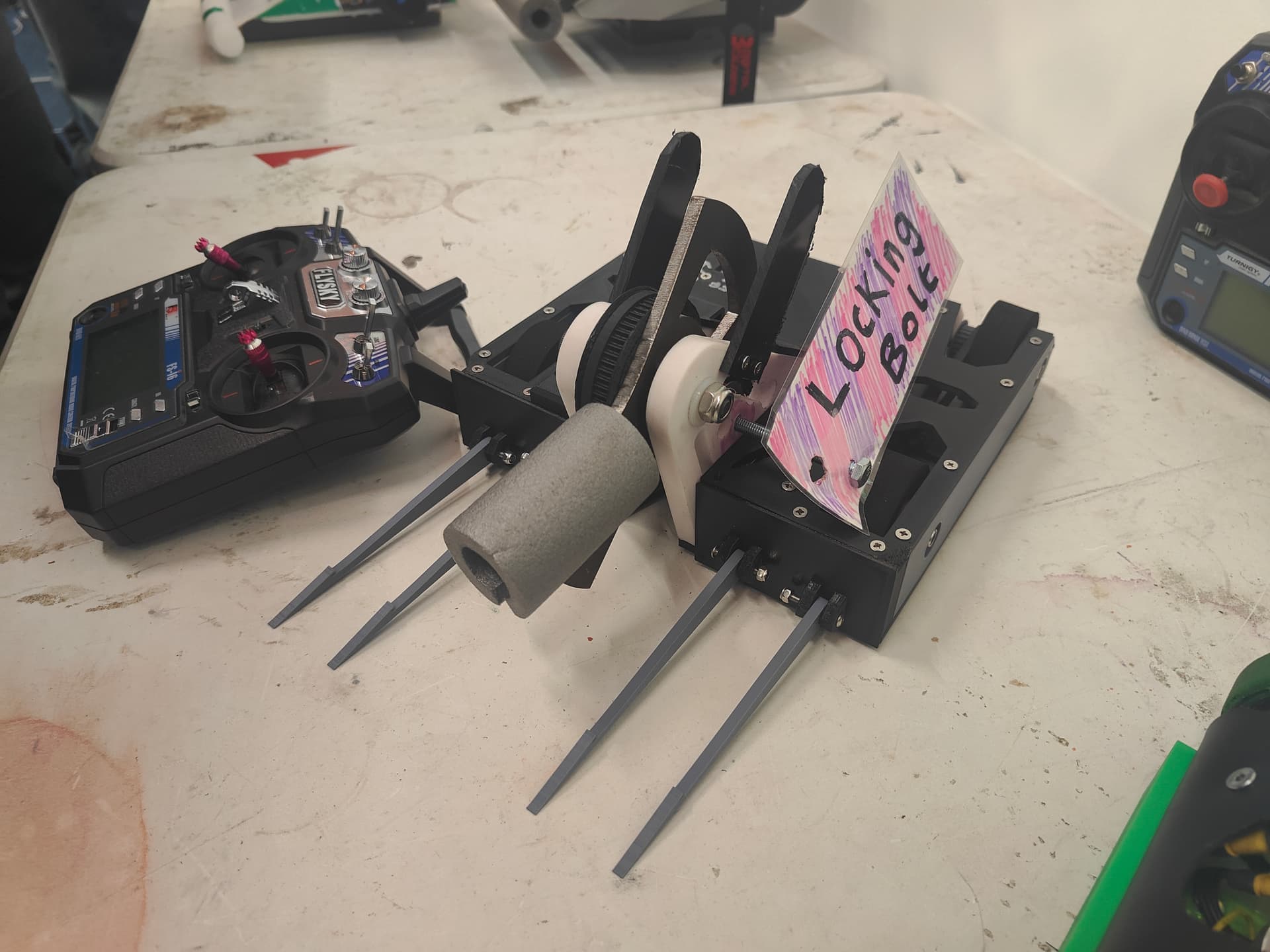
I have an incredibly bad habit of ignoring cradles and locking bars right up until the night before so to break that particular naughtiness I drafted a printed version which gently holds the robot and whispers sweet nothings and affirmations in it’s ear. I was intending to line it with foam to give it a bit more holding power as it was a little slippery but the little tabs in the cradle itself stopped it from being able to slide off.
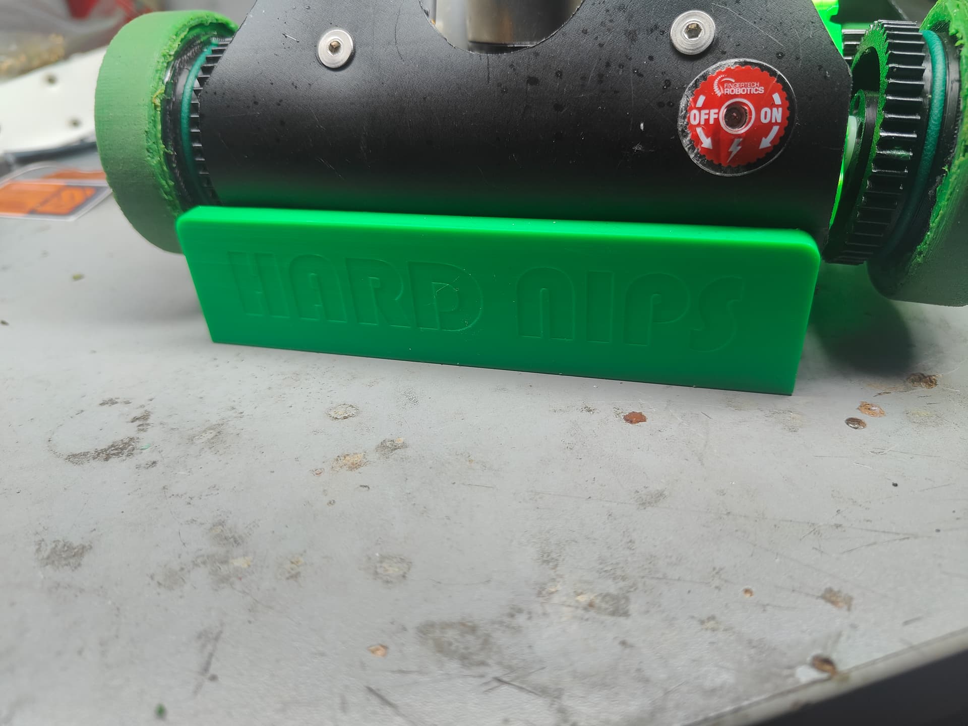
Naturally it had some subtle branding. I was going to use the multi coloured printing but that would have turned a 3 hour print into an 8 and burned a lot of material needlessly.
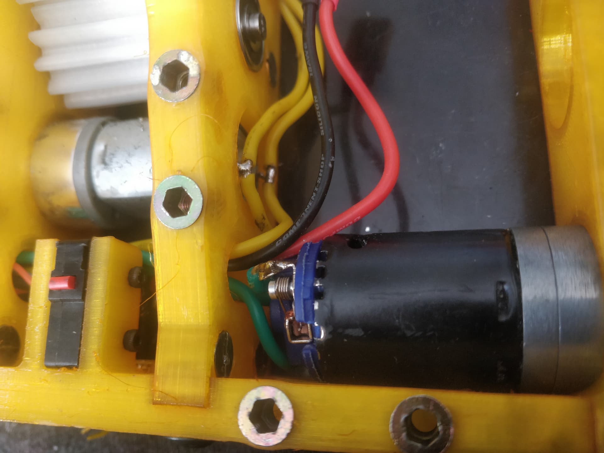
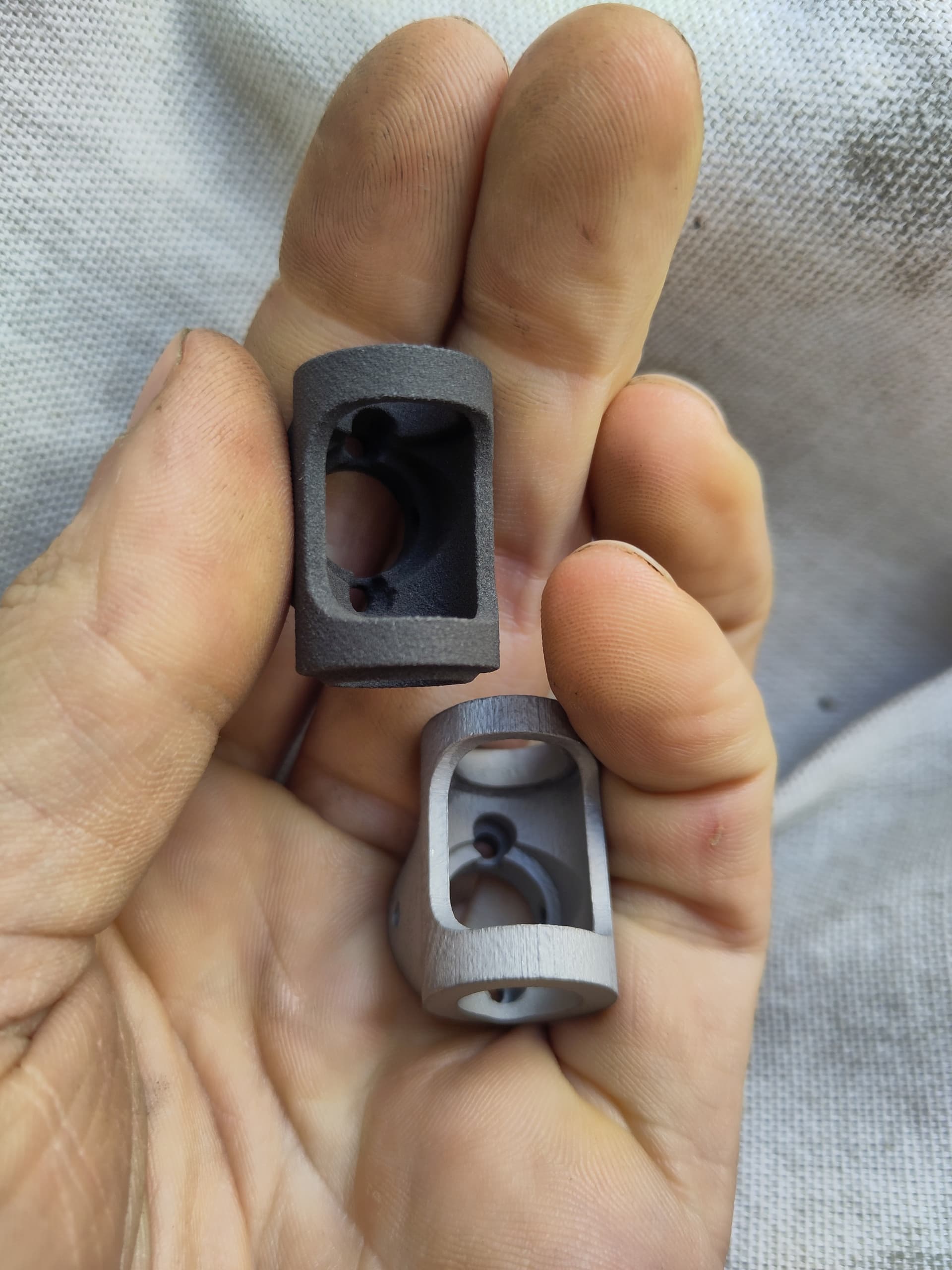
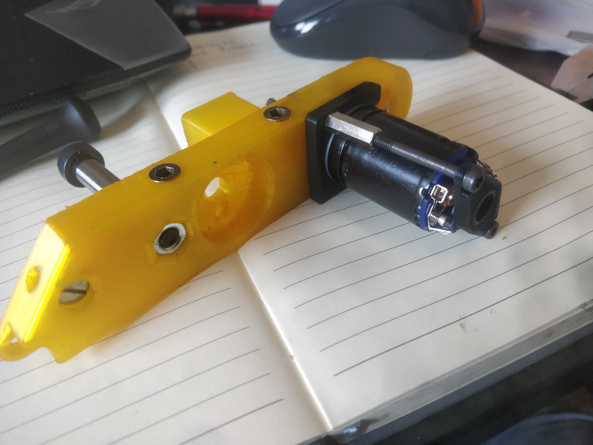
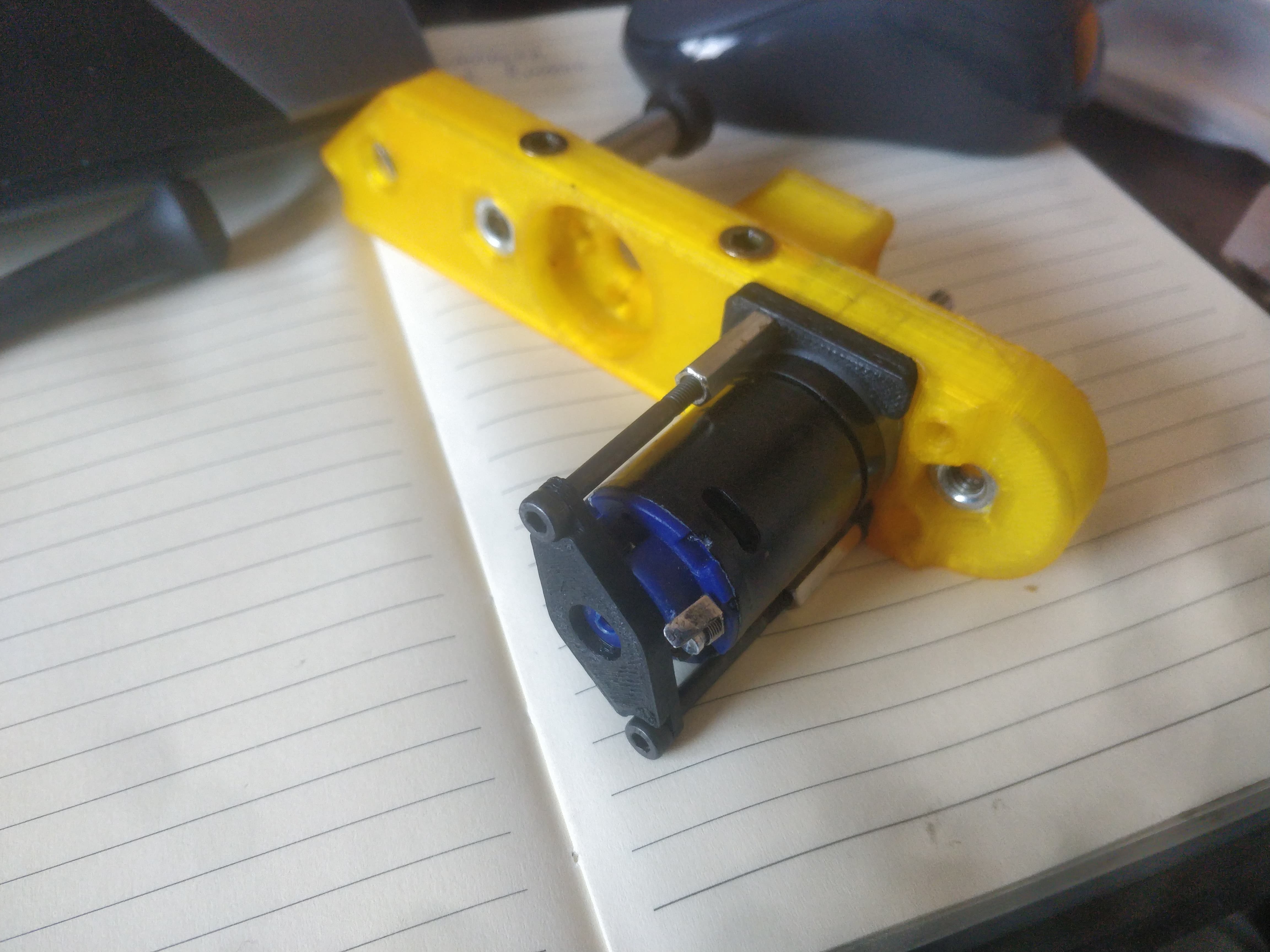
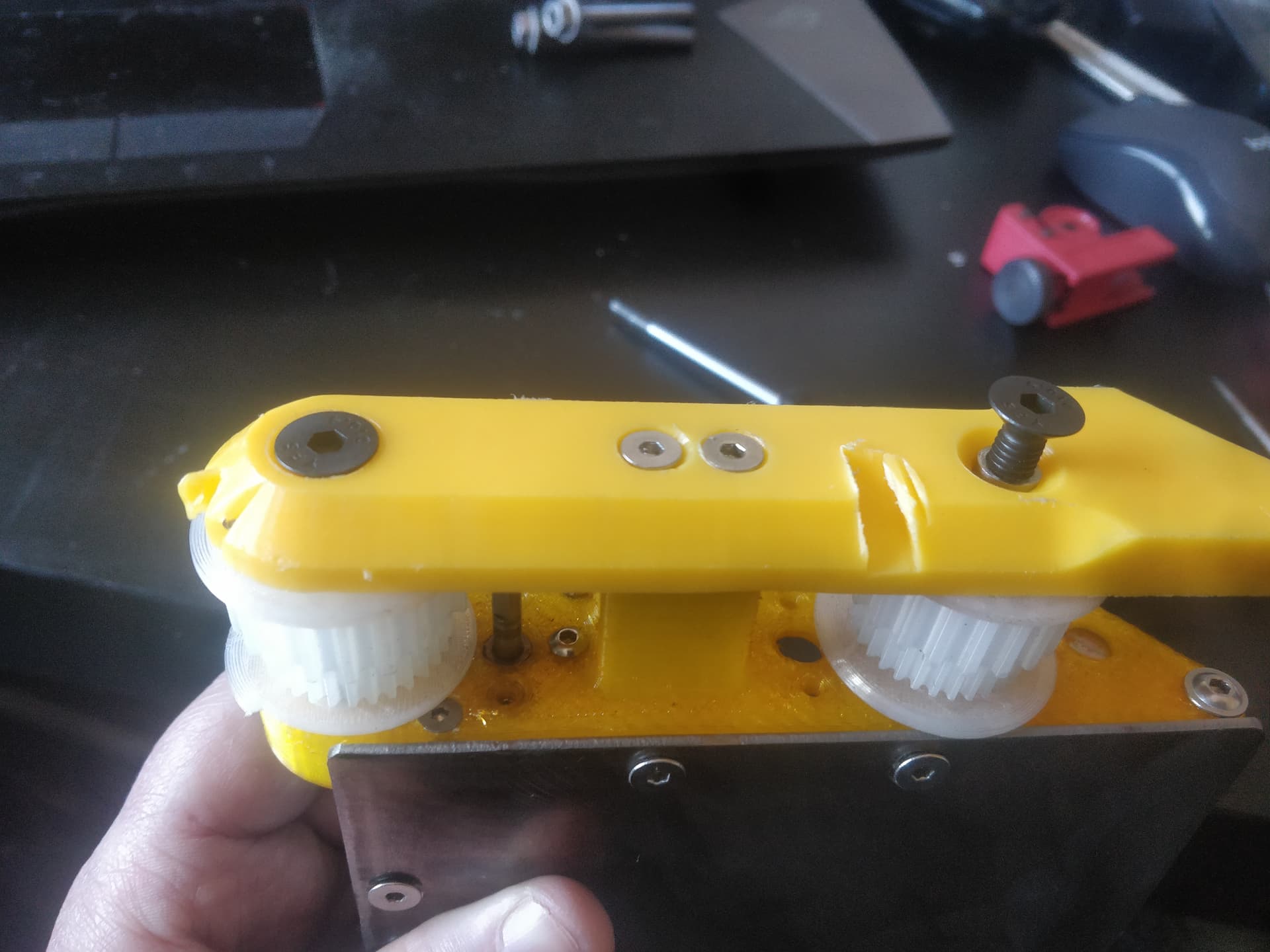
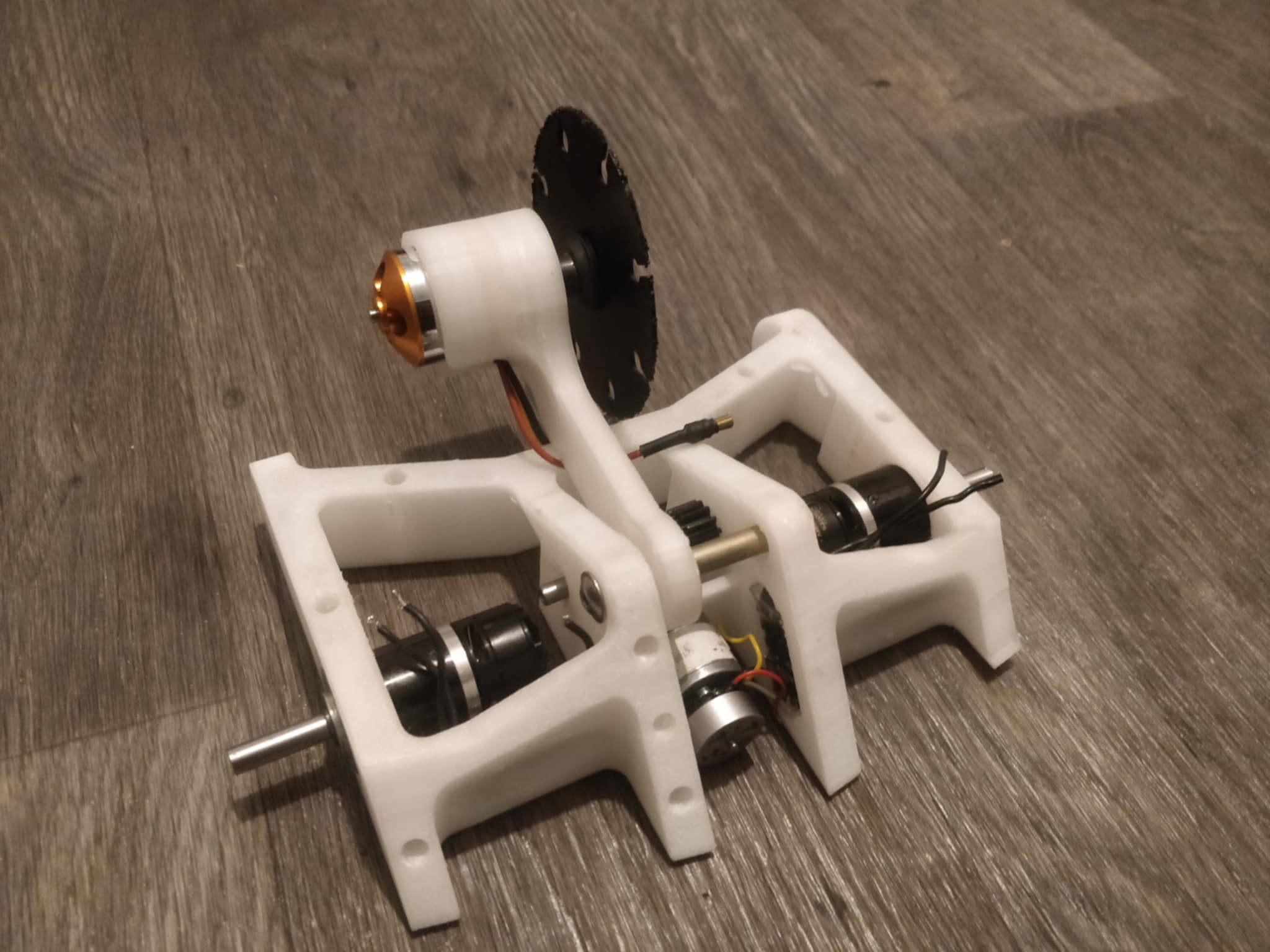
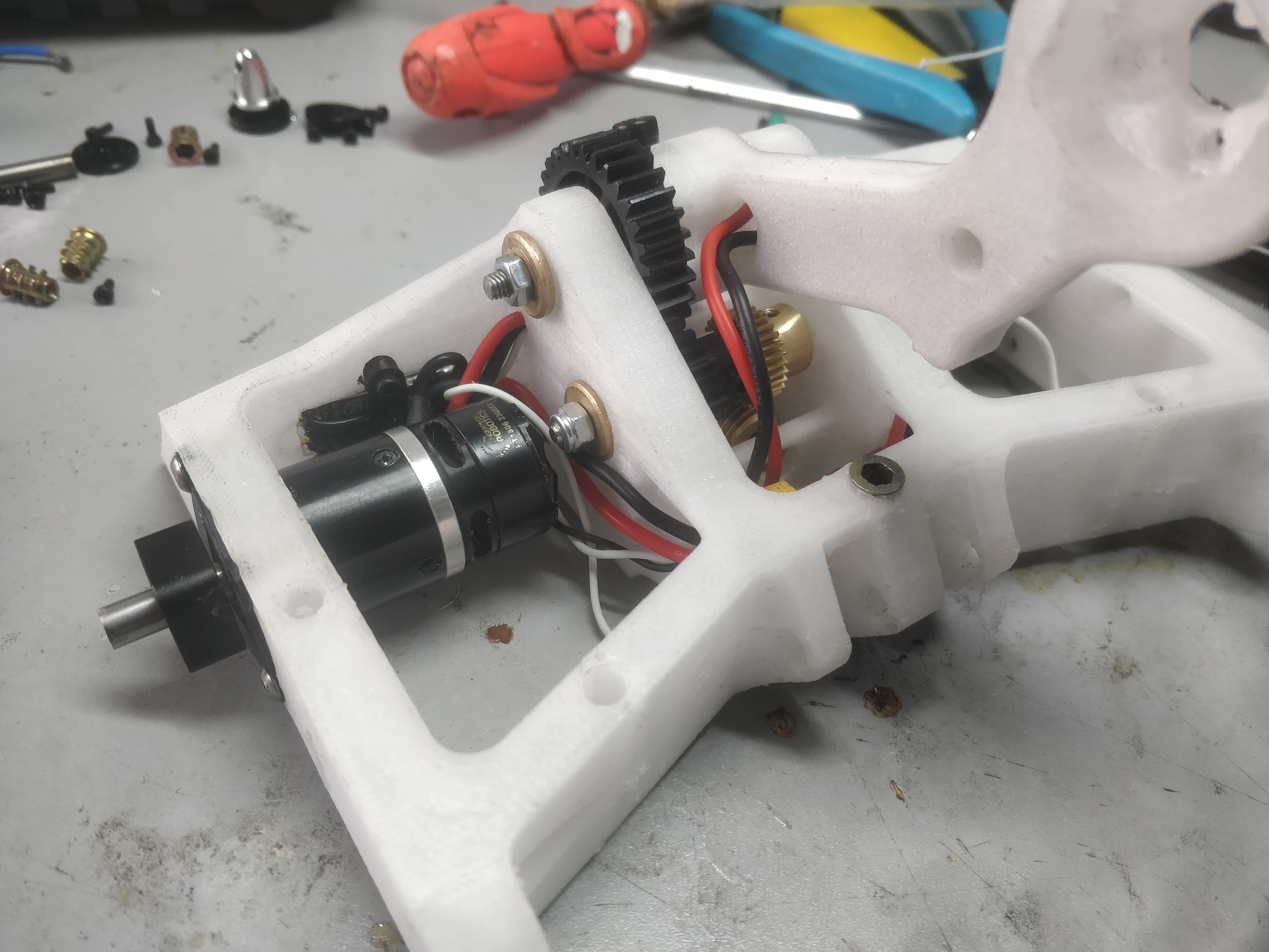
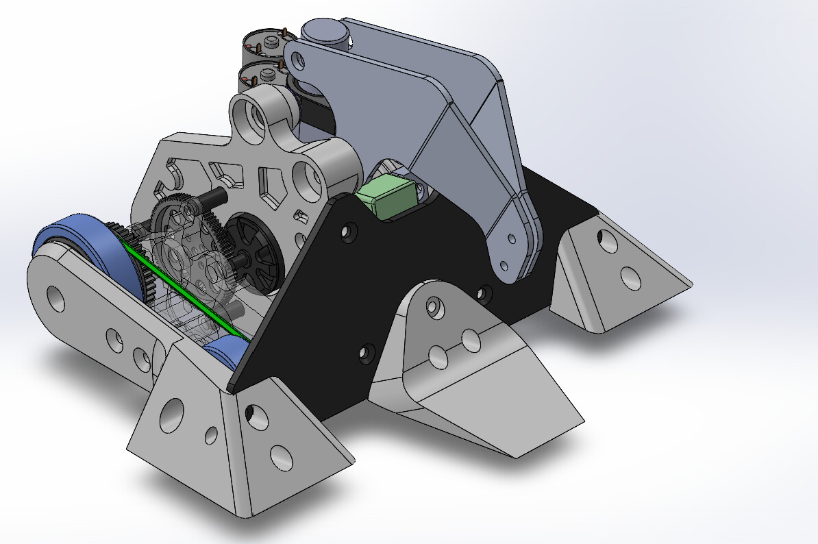
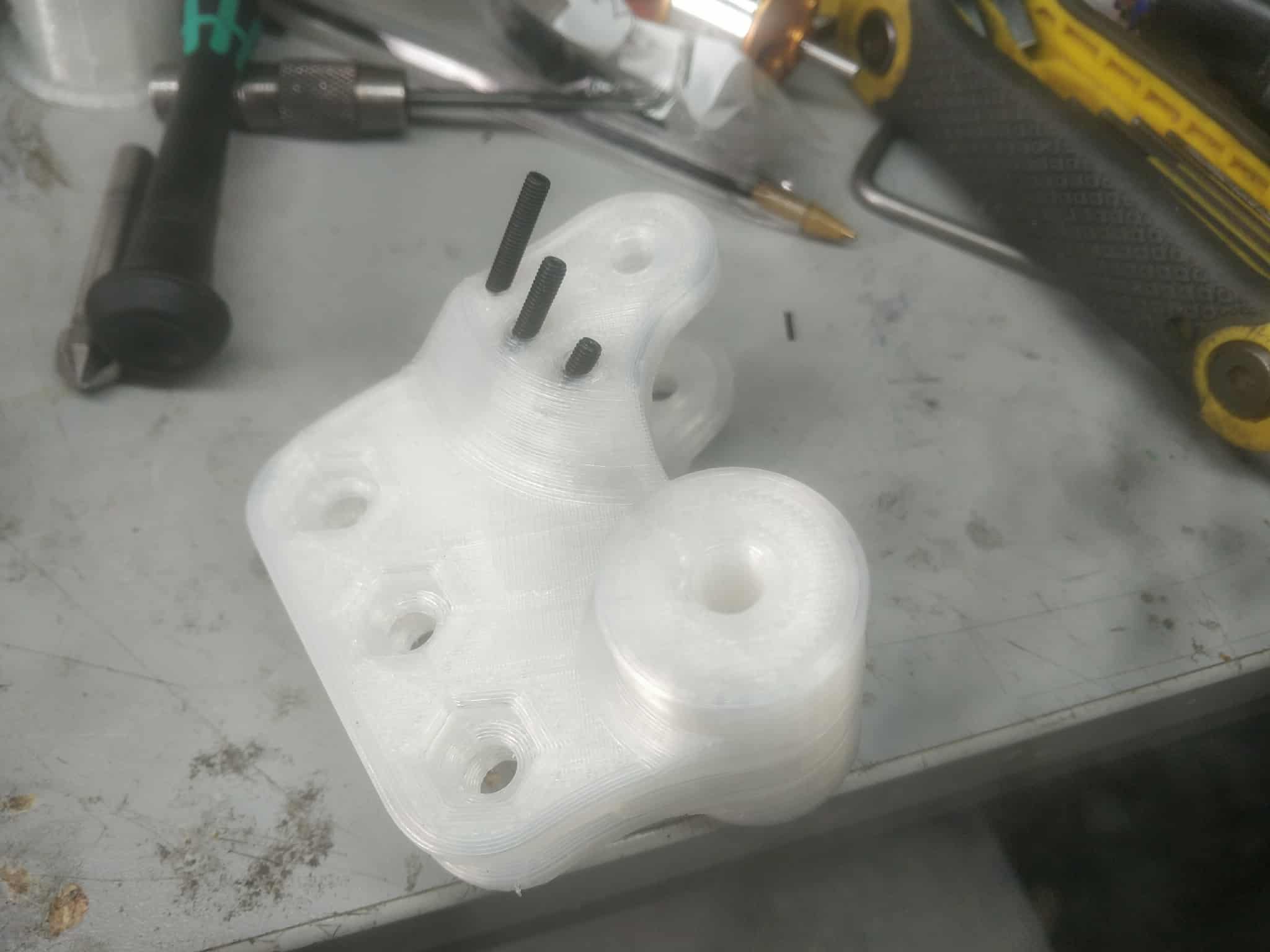
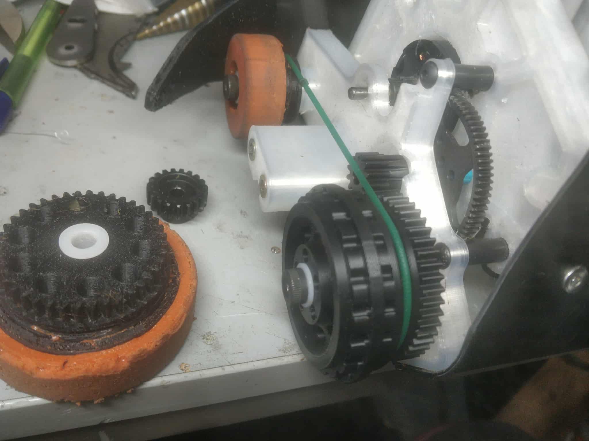
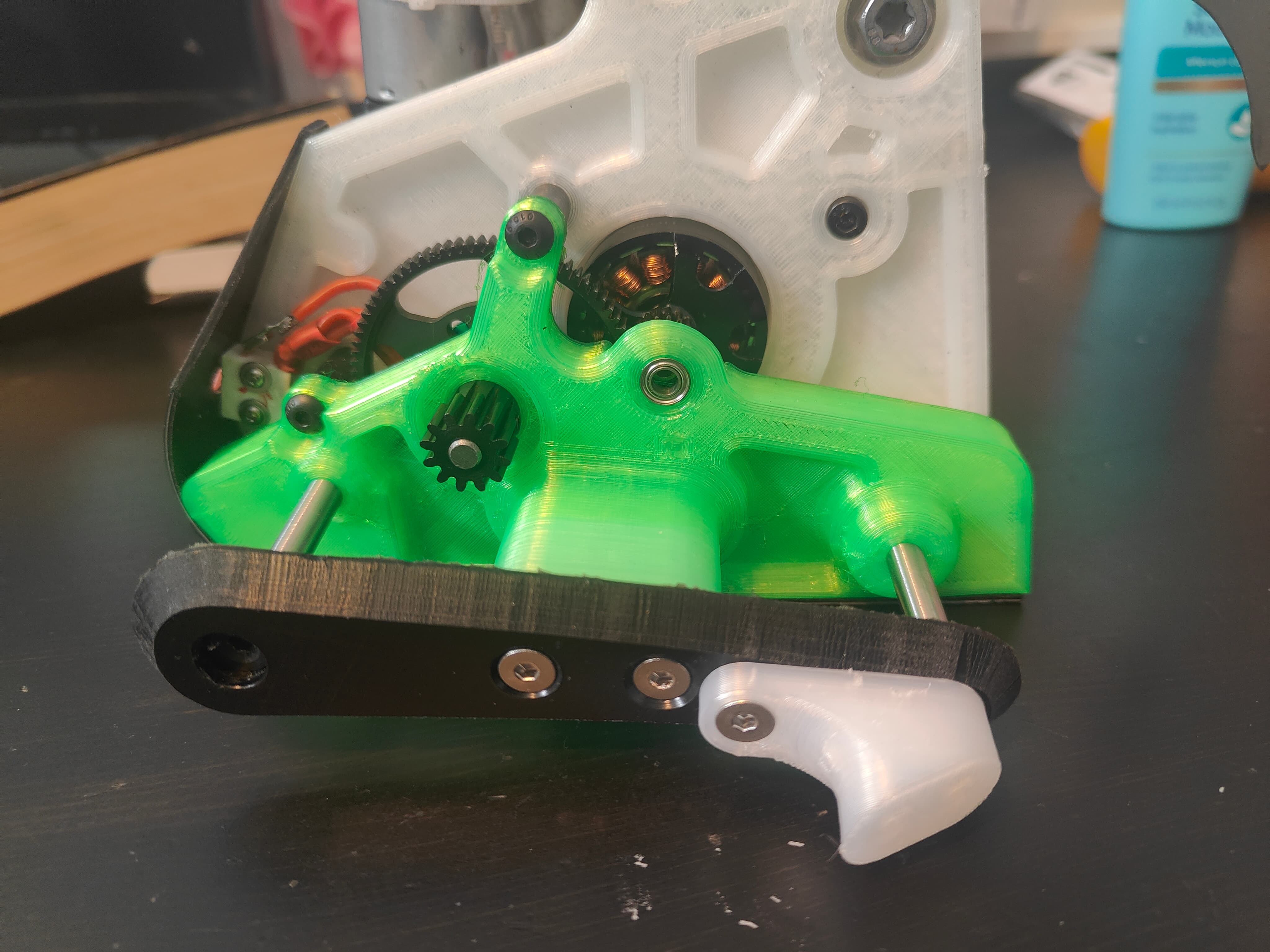
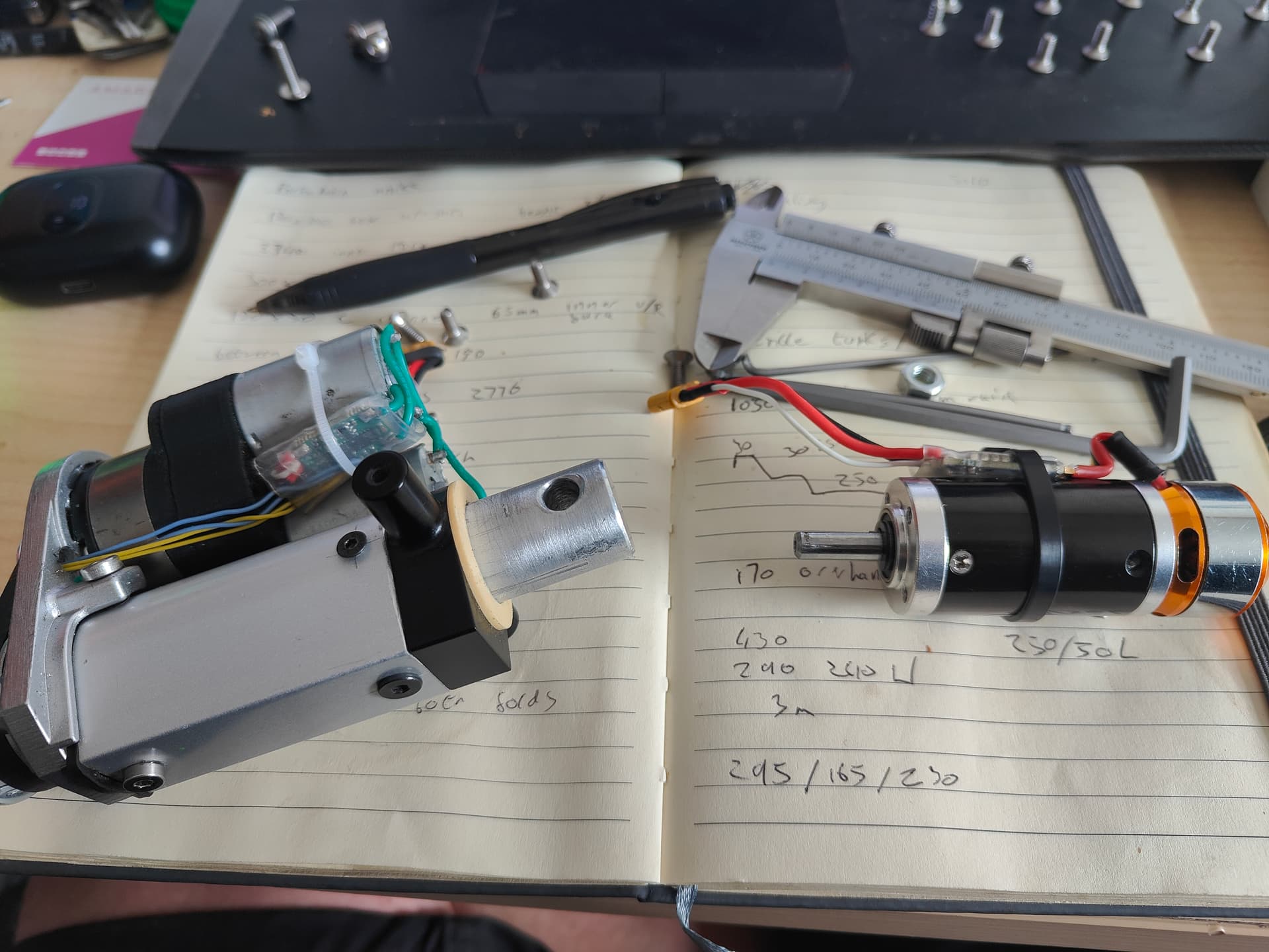
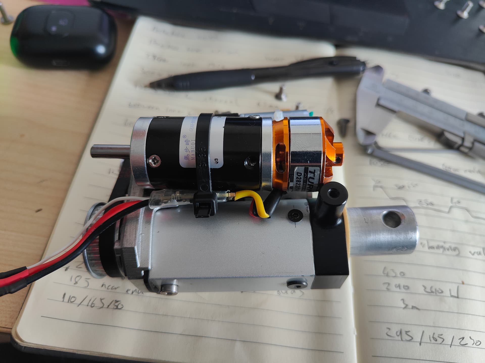
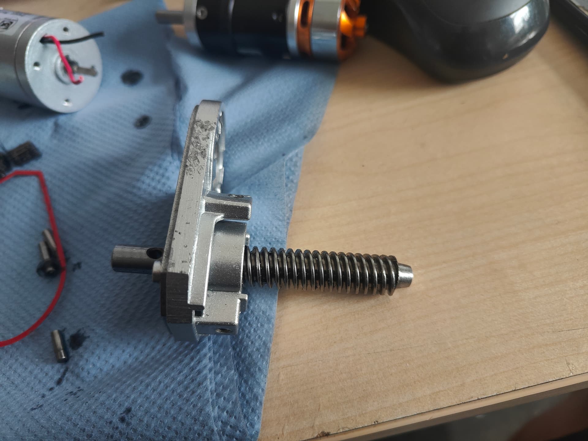
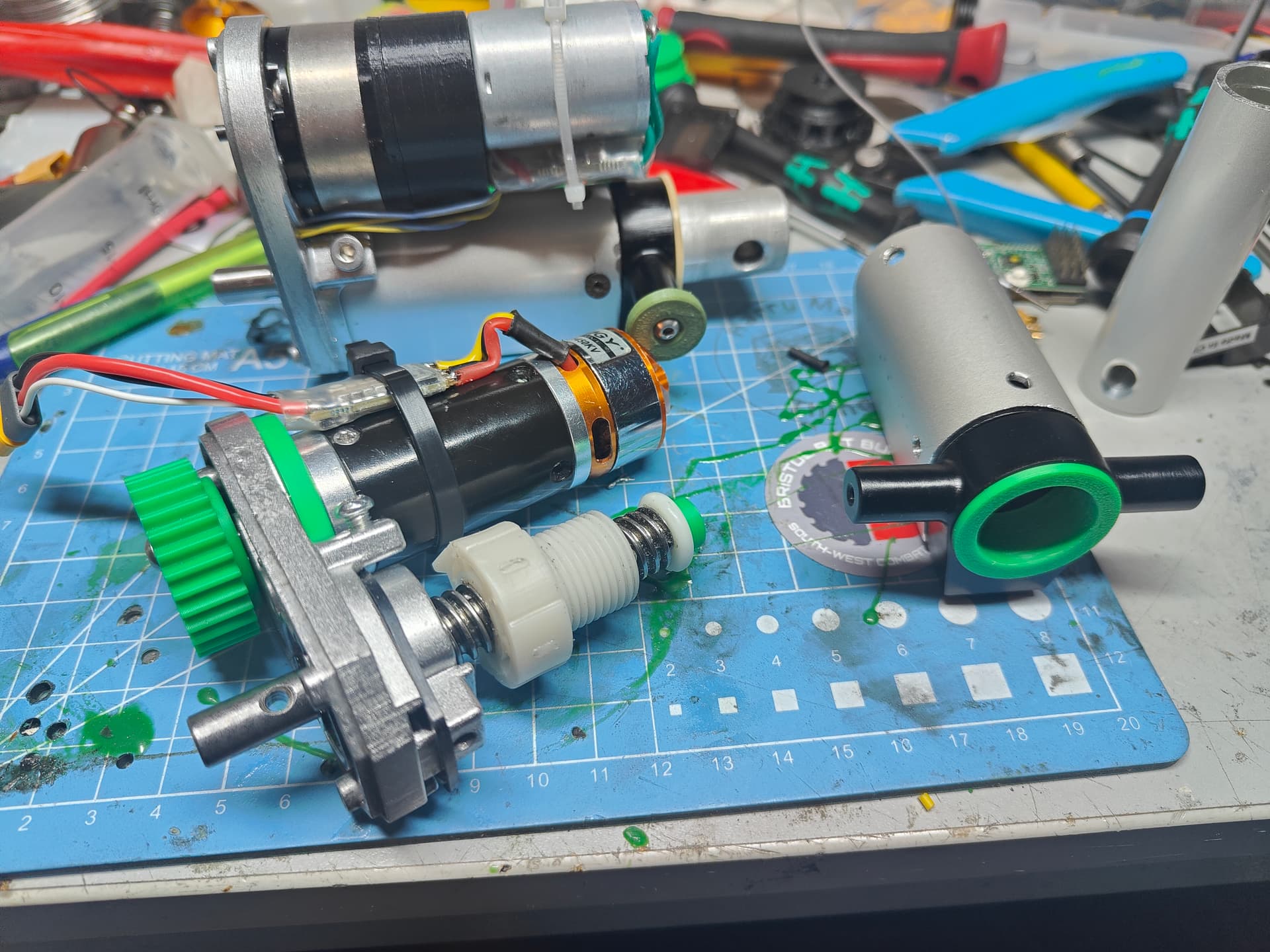
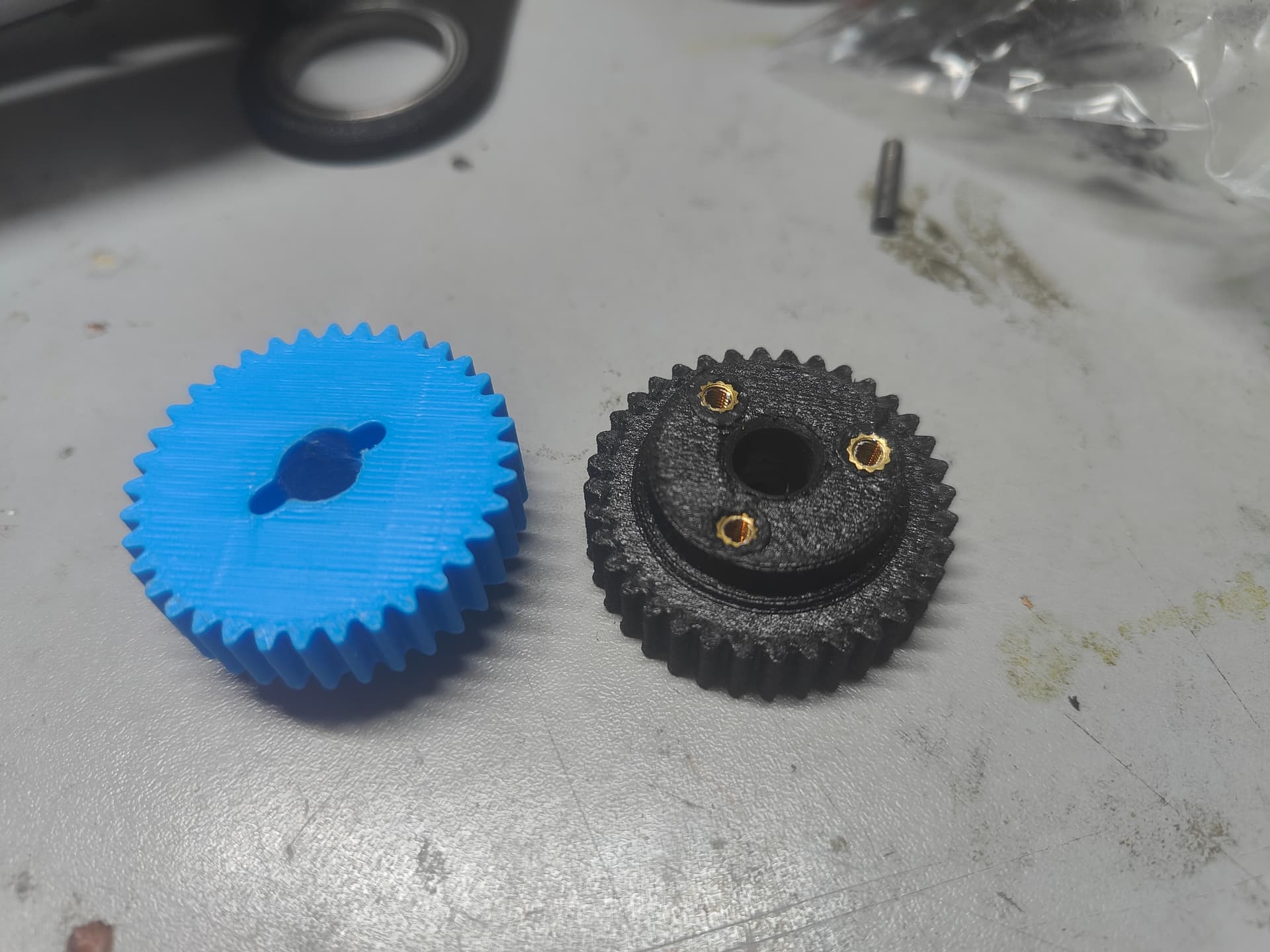
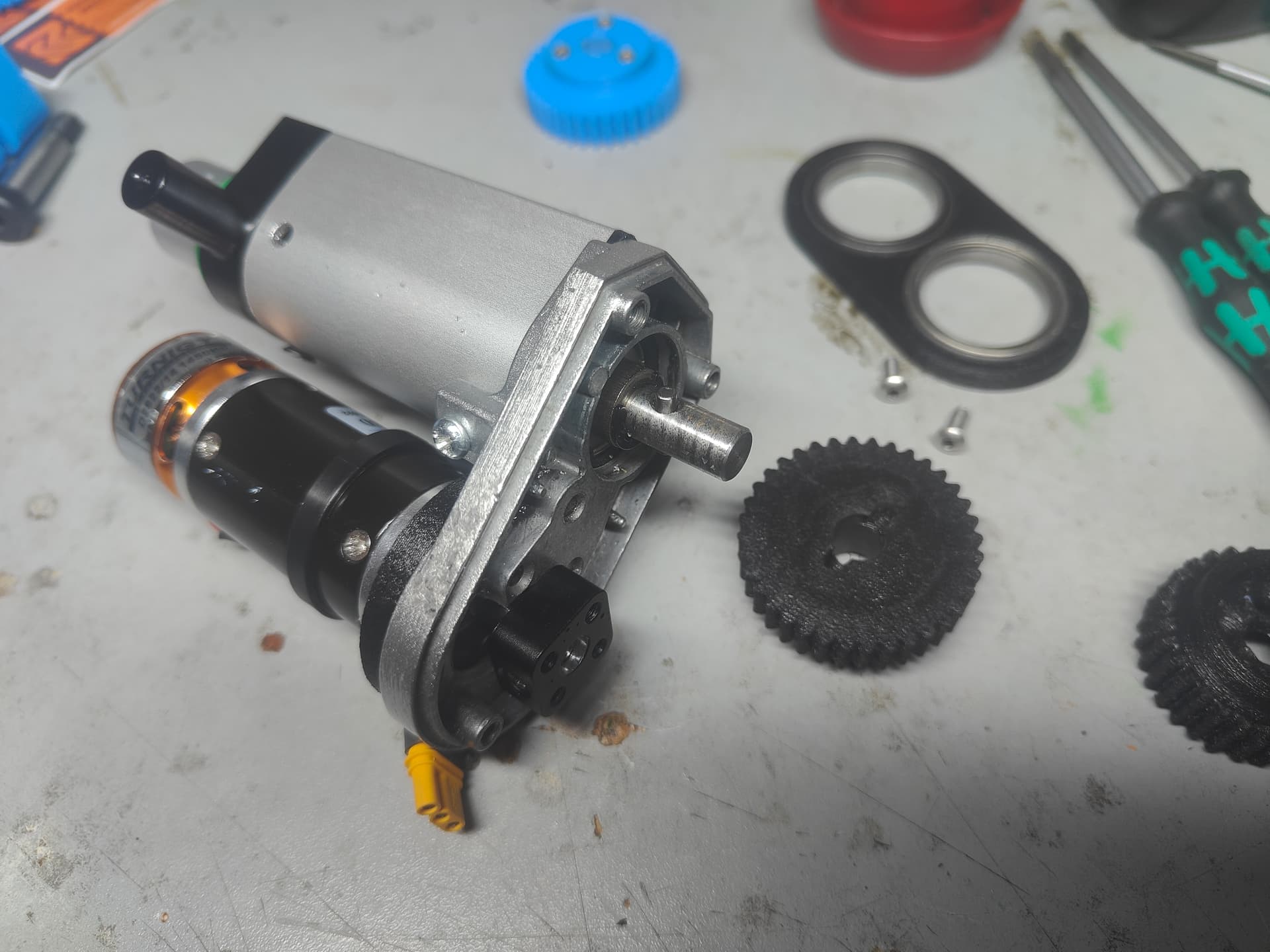
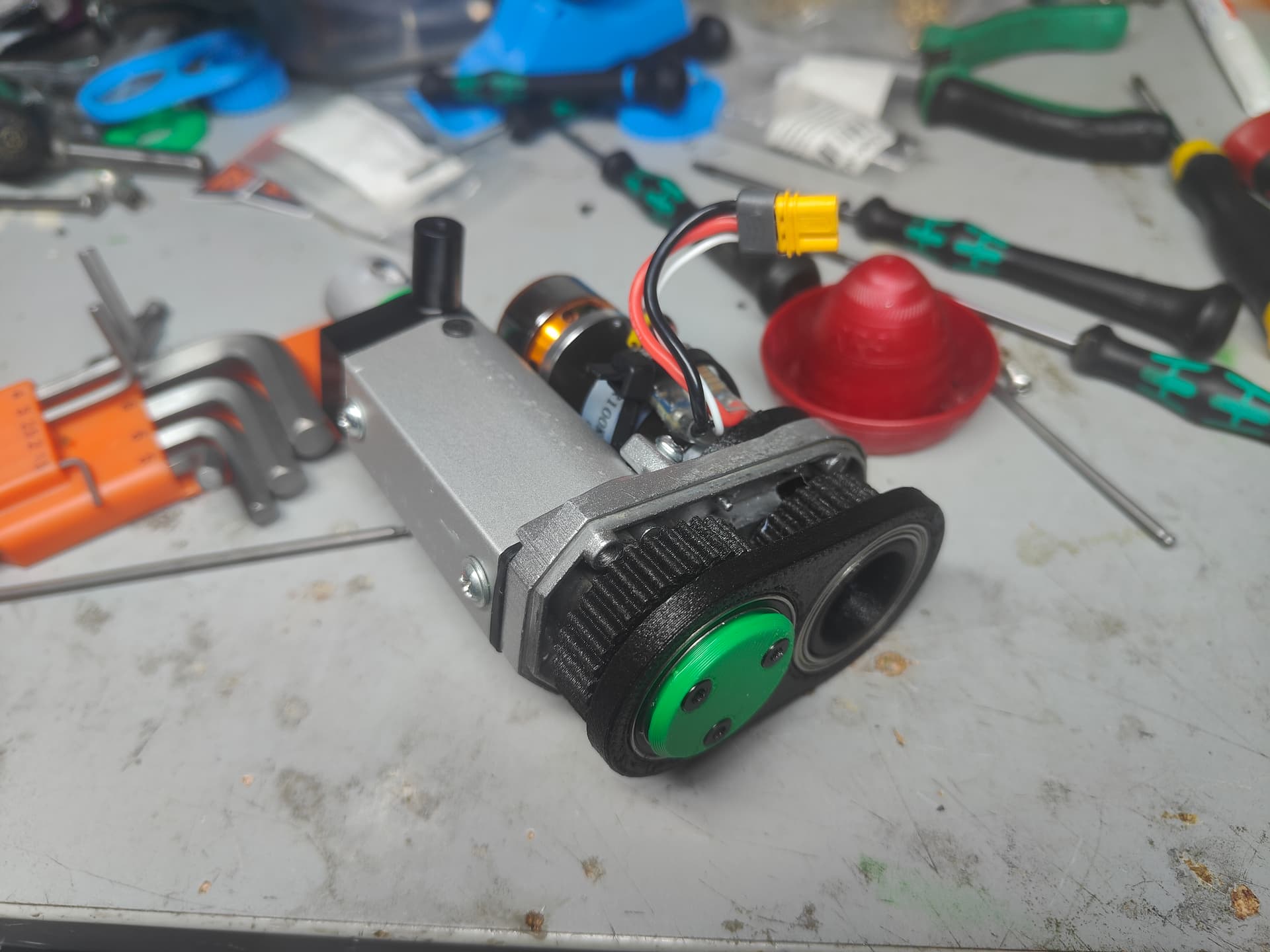
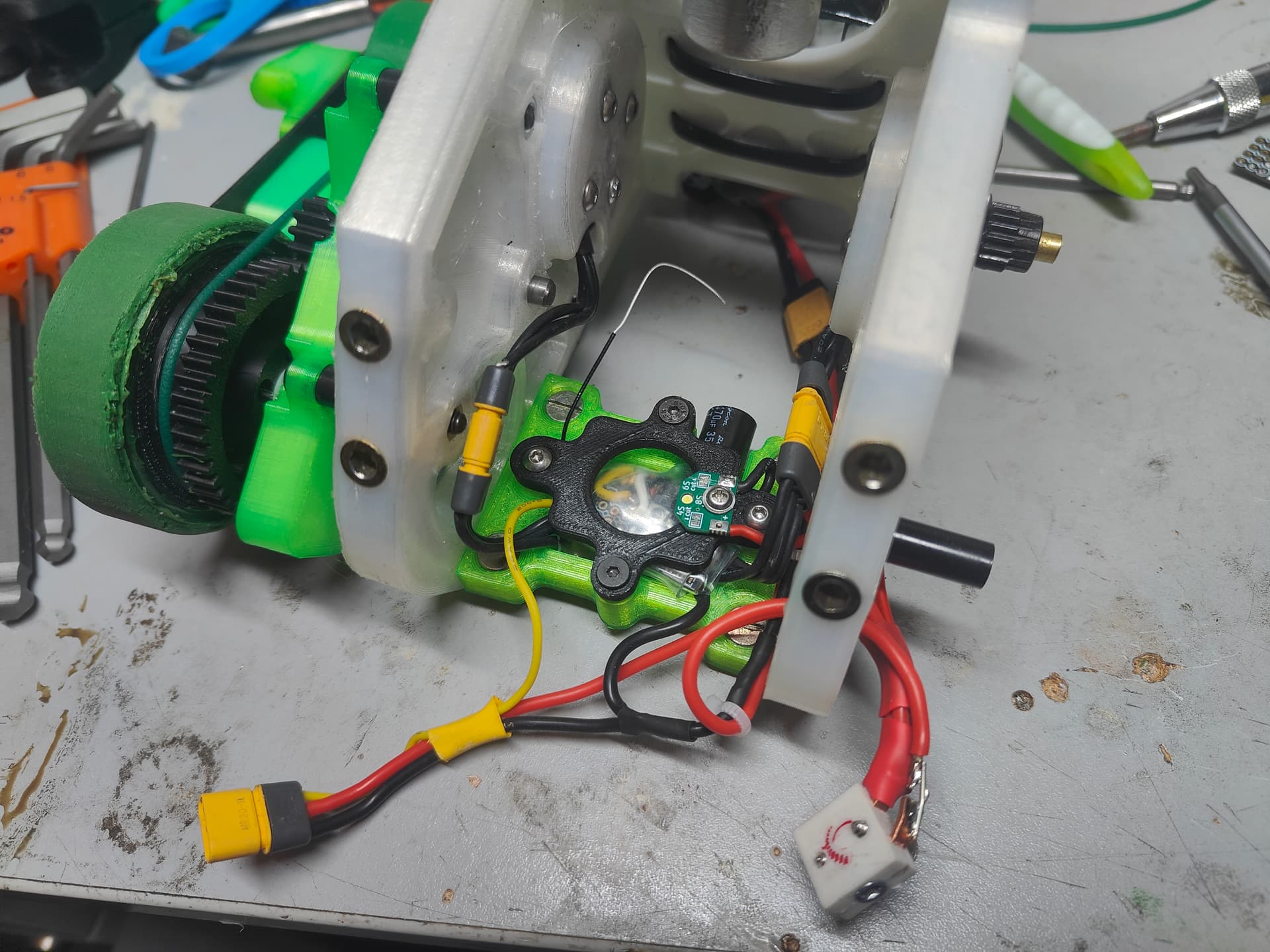
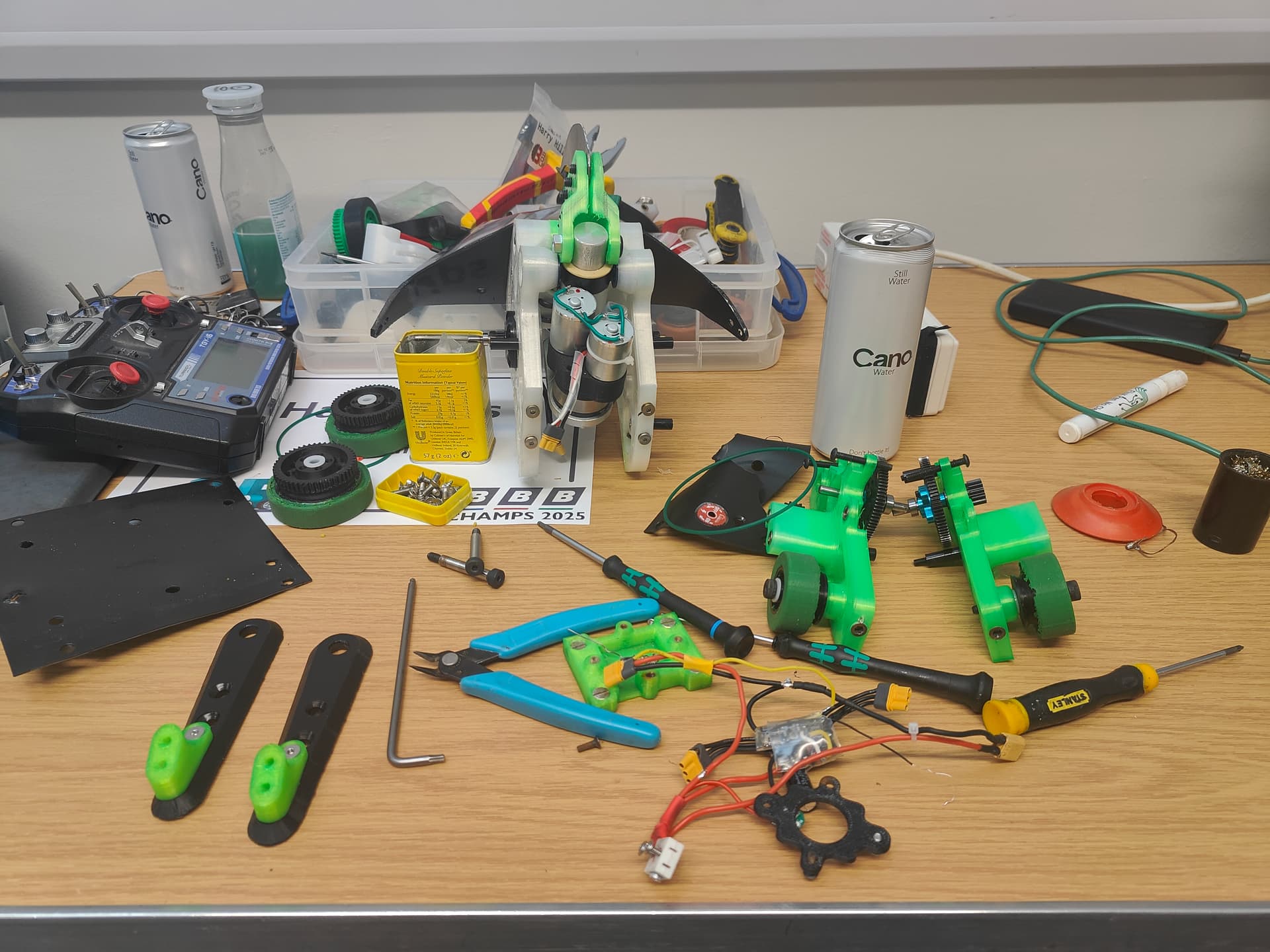
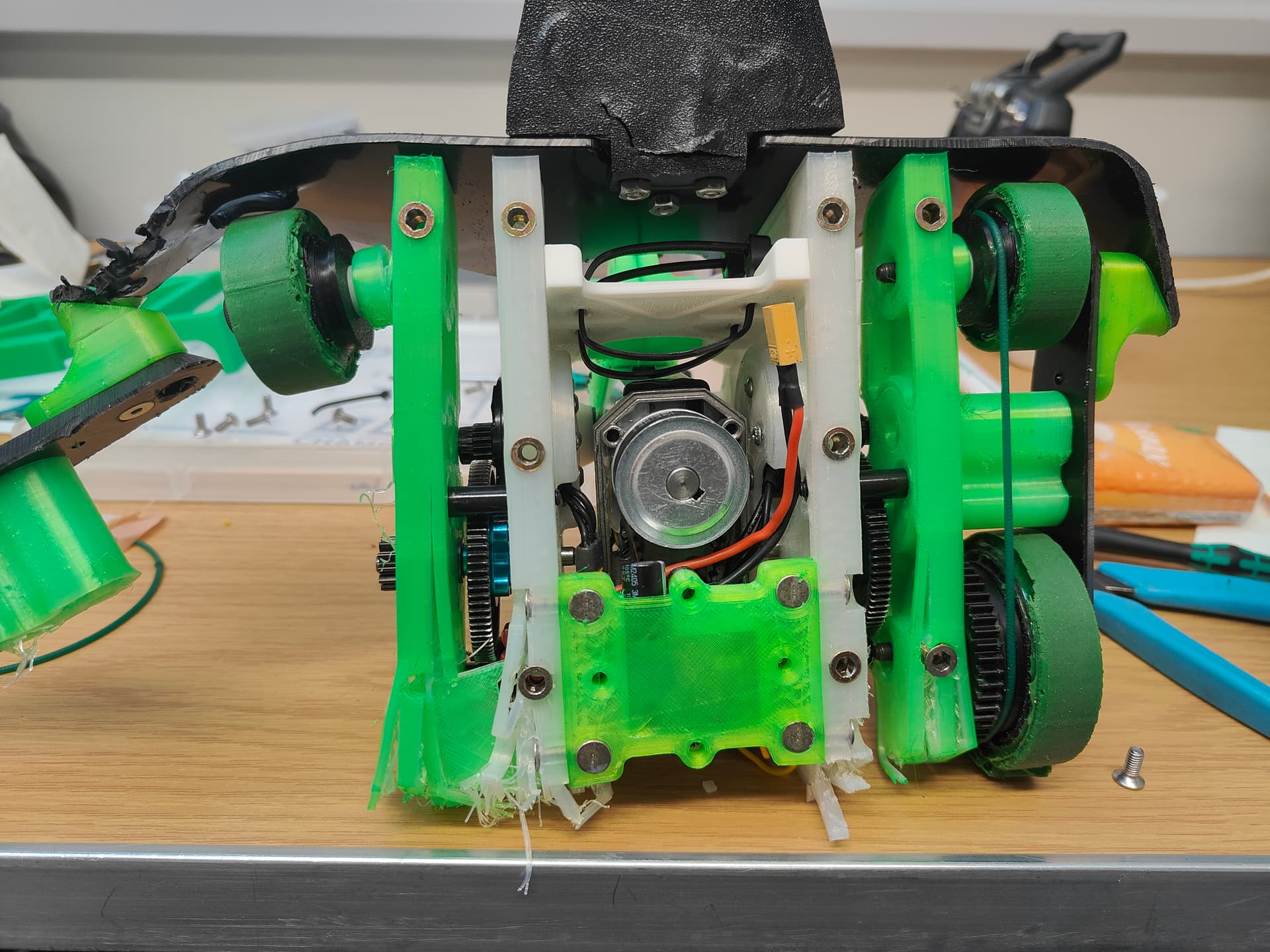
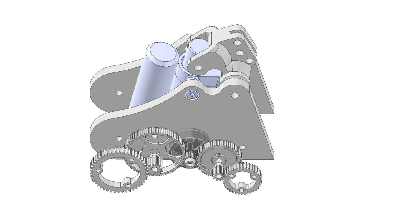
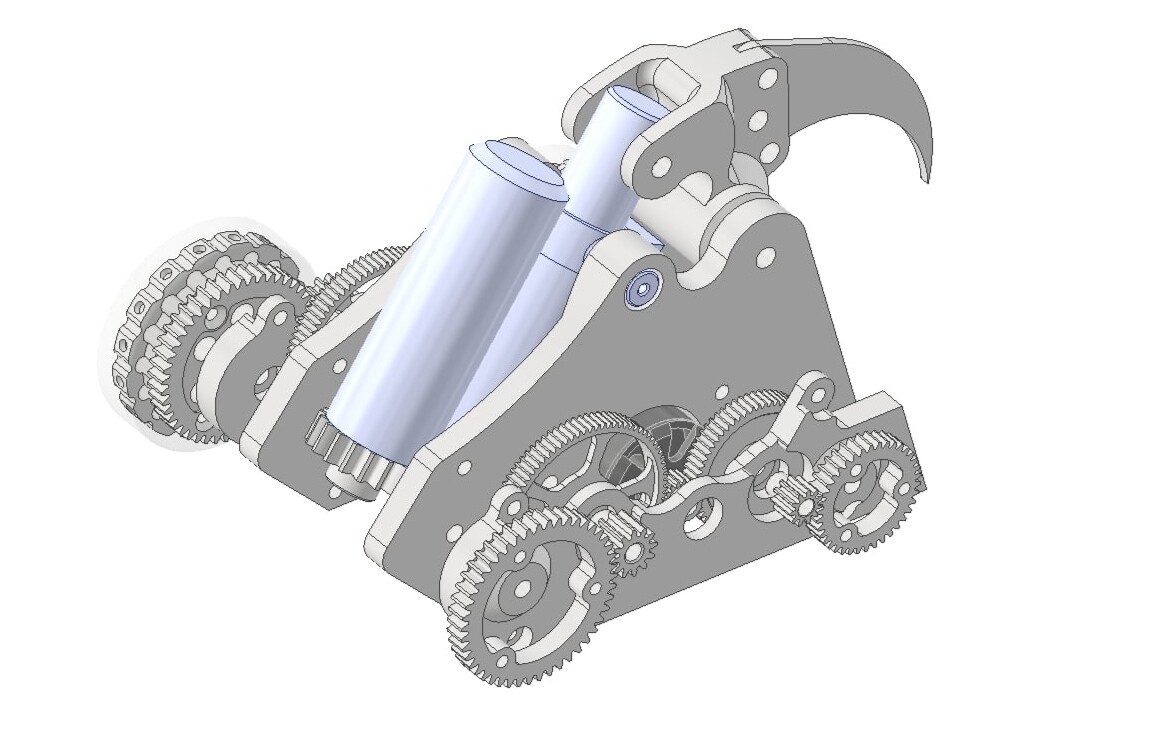
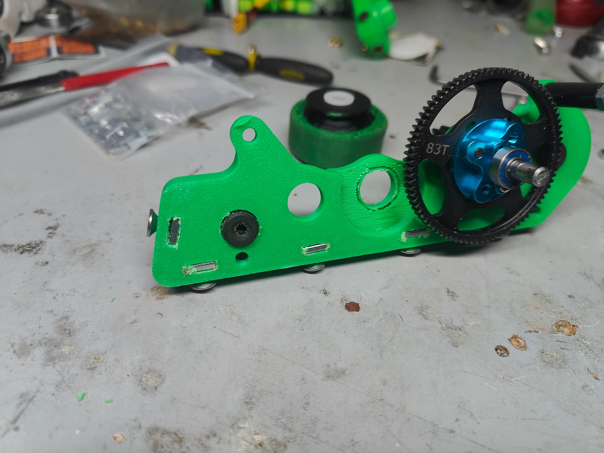
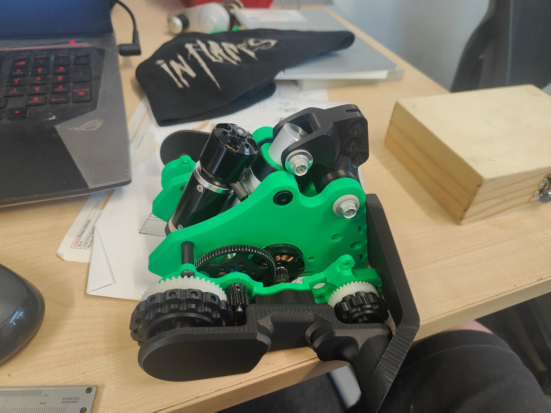
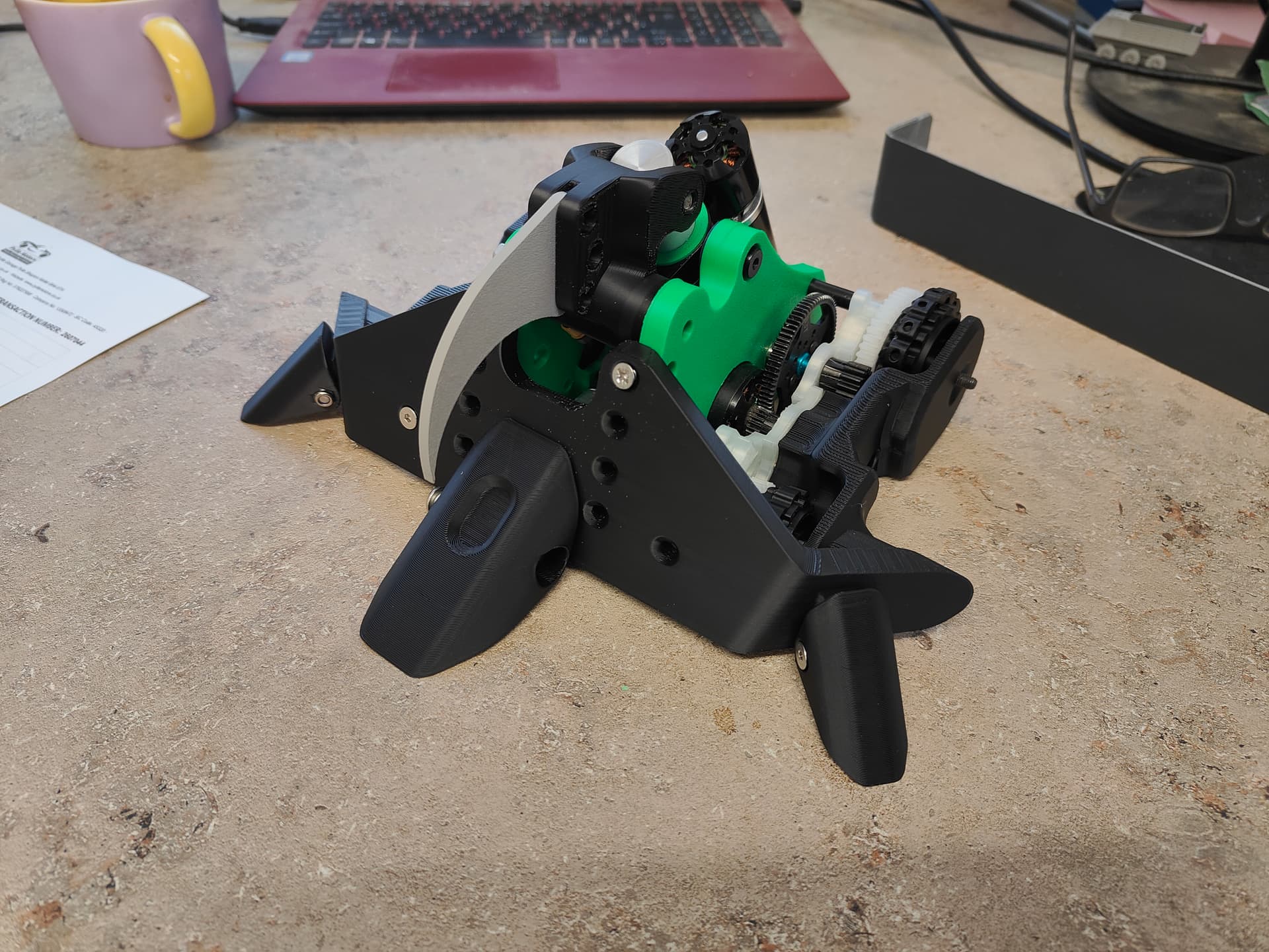
I was exceptionally busy in the direct lead up to champs which I wasn’t expecting so lots of the bigger jobs had to happen over the 2-3 days preceding it. One system that was getting attention was the brushless actuator I began in the last post. Throwing caution and best practice to the wind I redrew the gears and did a trial in PLA before moving on to CF nylon - which I was mostly using to see how it printed. It engages the lead screw via a cross pin like the stock gear and then has an endcap that bolts to the other side. I still am a fan of these little heat press inserts. So long as you have reasonable expectations for them it’s a great way of Making Thread Happen.
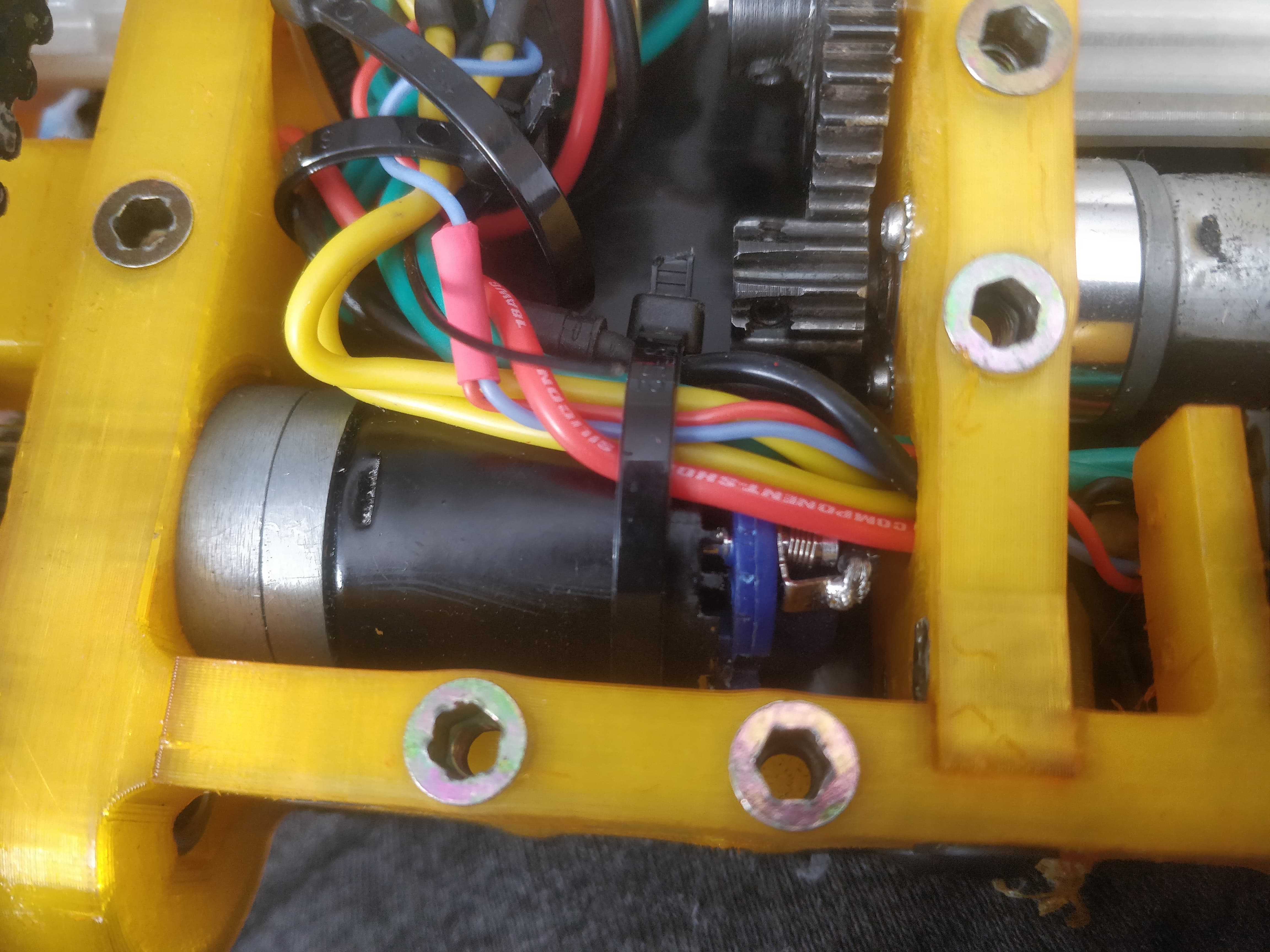
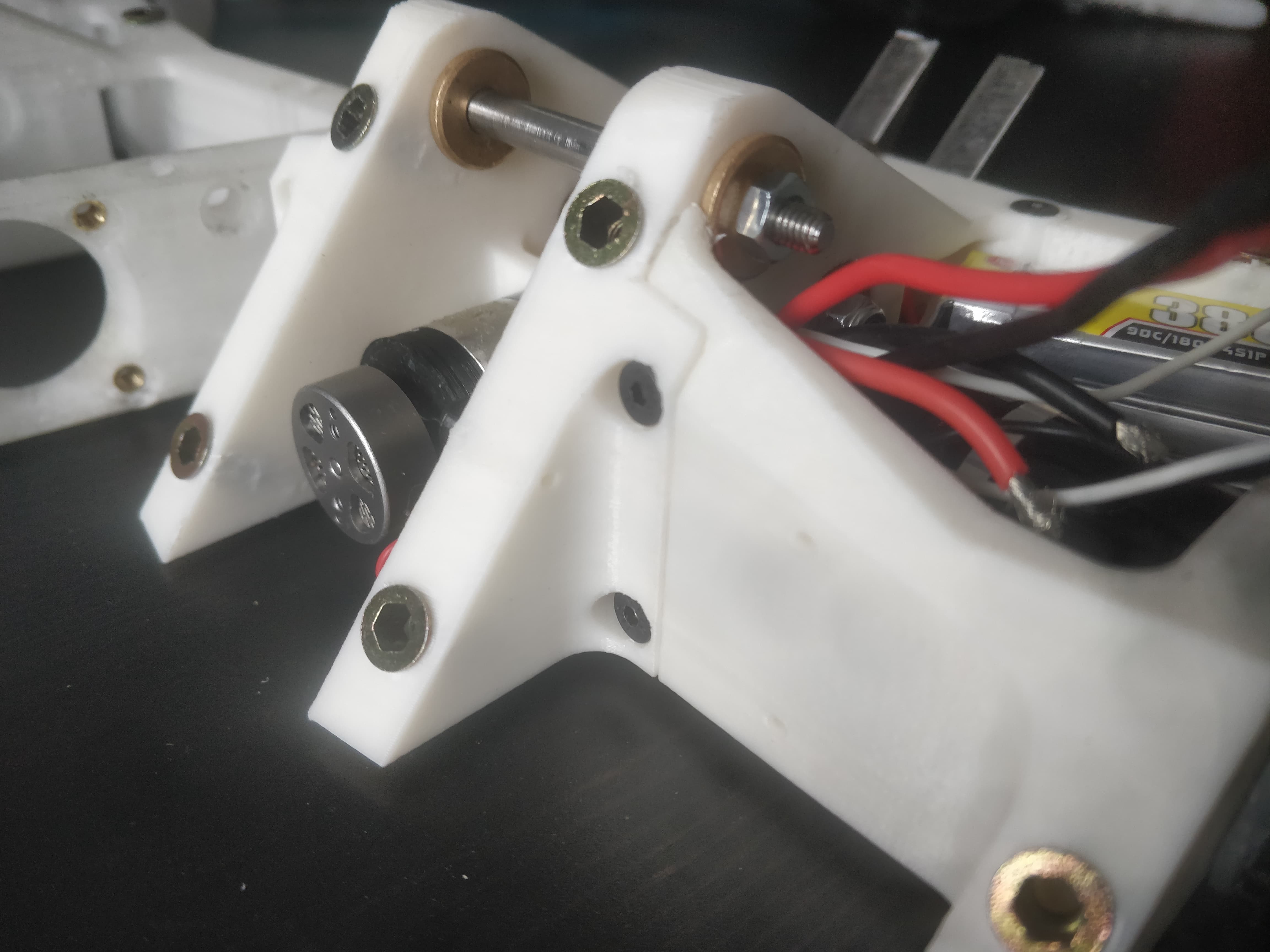
My main concern with the backup actuator (Bactuator?) was the gears being able to force themselves out of mesh as they are both poorly cantilevered and just take up resistance in the bad neighbourhoods of Shred City. To cure this I grabbed my container of random bearings and shook it upside down until something interesting fell out. I have a huge baggie of these thin profile 25mm bearings so made a housing around them and gave the gear models a 25mm plain portion.
This just lashes them together and stops the gears from being able to pull away from each other. It’s free floating, only axially retained by a printed endcap that goes on the non motor side.
Feels much better like this - though it’s a strange solution that a problem that shouldn’t exist. Now that I know I can print something rigid and strong enough I would do things differently. I would jettison the aluminium ‘bridge’ and make one out of CF nylon that has the geometry I want and a better PCD and I could properly put a transfer case together.
Now I’d had a myriad of issues with the actuator setup and I couldn’t quite see what the issue could be as the problem morphed somewhat.
I alluded to vague “troubles” previously but can narrow down the theory with only one bit not making good sense.
In my testing I had the jaw fail to ‘pick up’ and start moving under movement from the stick. Sometimes it would whine, sometimes it would go sluggishly but never very consistently. Using my absolute towering intellect I narrowed it down to the limit switches, the ESC and the motors. Yes by power of elimination, Facts and Logic I had diagnosed the problem was at least one part of a 3 part assembly with up to 3 possible options.
God I’m smart.
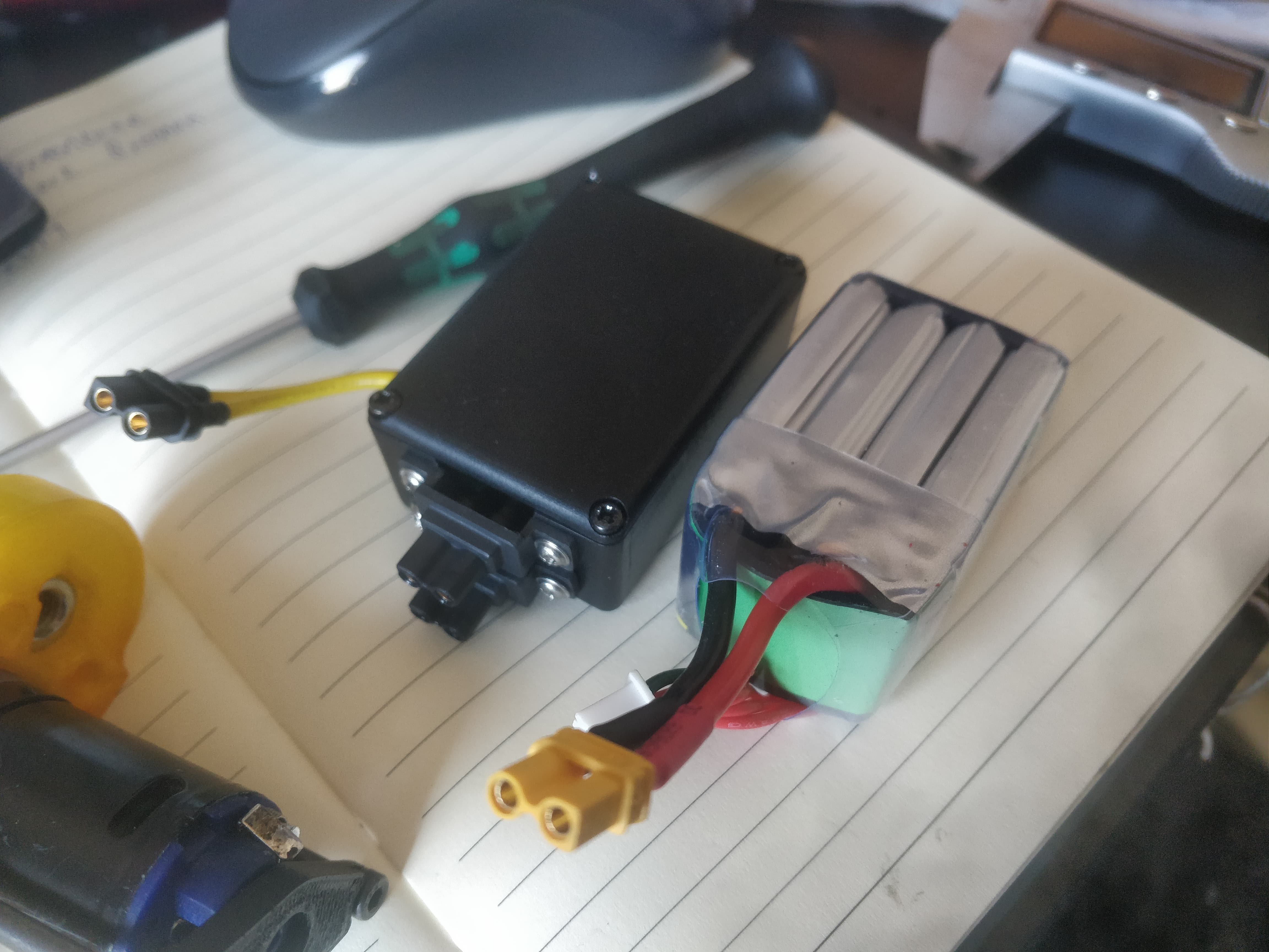
I was then thrown for a loop as the BBB esc just stopped arming. Different channels? Nada. Different receivers? Zilch. Prayers and candles? Ambient but unhelpful. With the full support of the BBB electronics arm I got hot shipped a replacement and given some things to try. Resetting the ESC with the handy dandy programmer was something I should have potentially already tried, but with my outdated 2010 era style of troubleshooting it got overlooked in the moment.
I had an ESC that would arm again! It still wasn’t happy moving but that was a third of the potential culprits discounted. The limit switches in their ad-hoc arrangement were next proved to be working fine. My sights fell on the motors.
Spoiler alert: it was the motors.
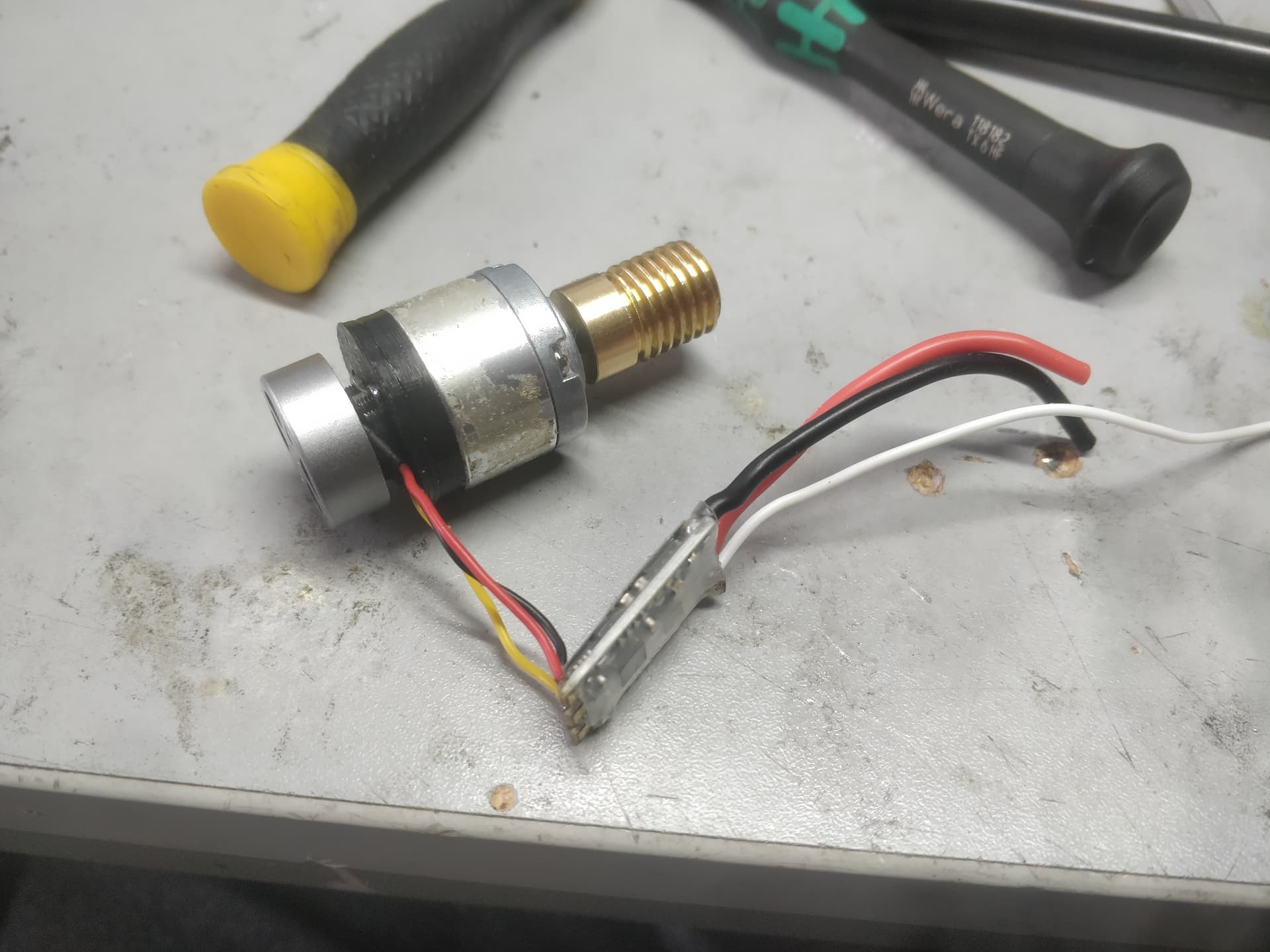
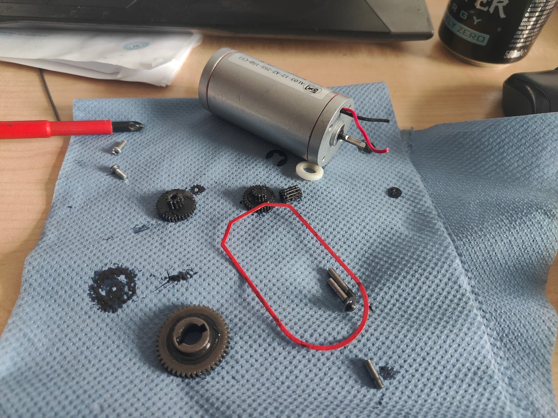
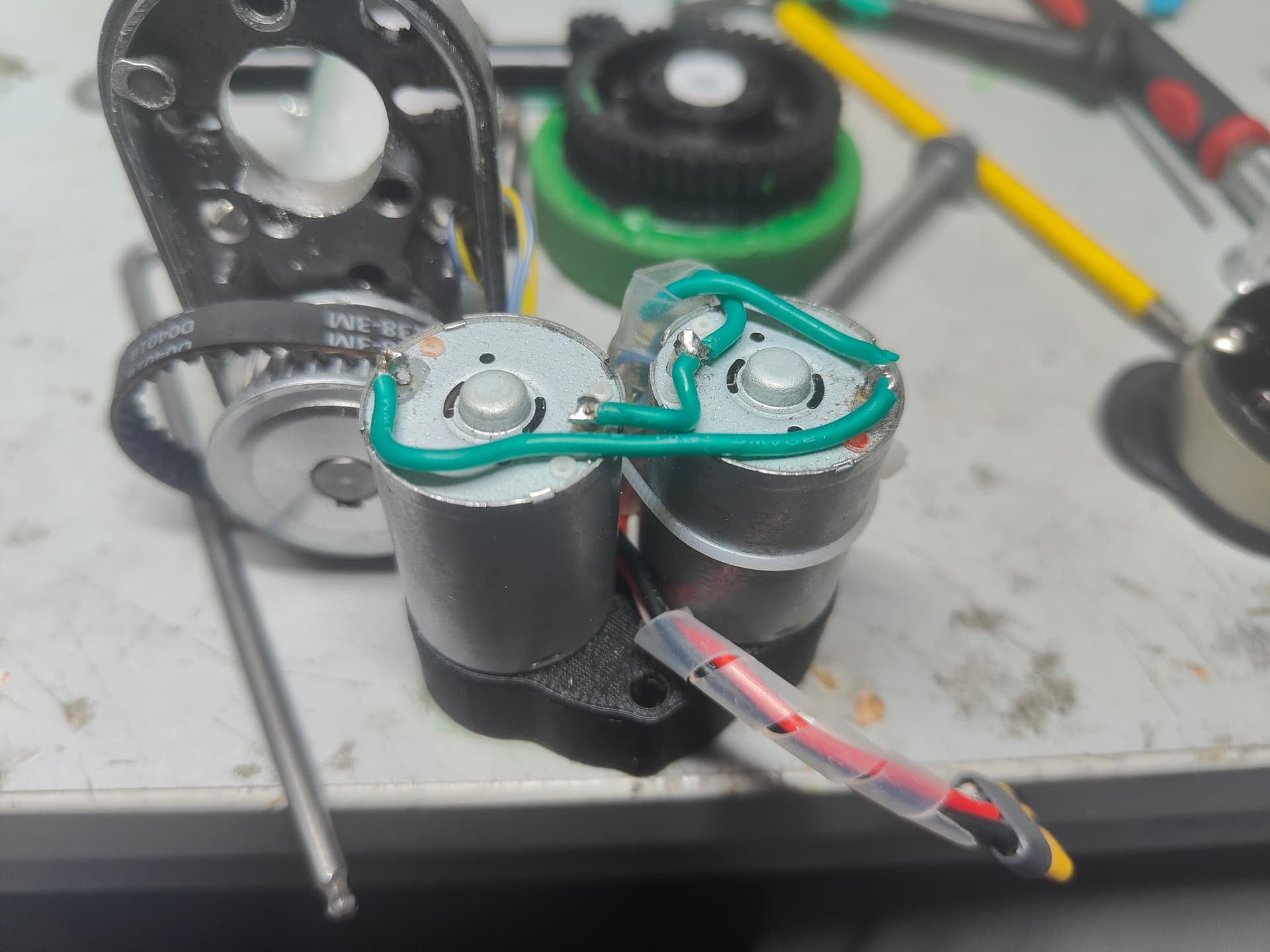
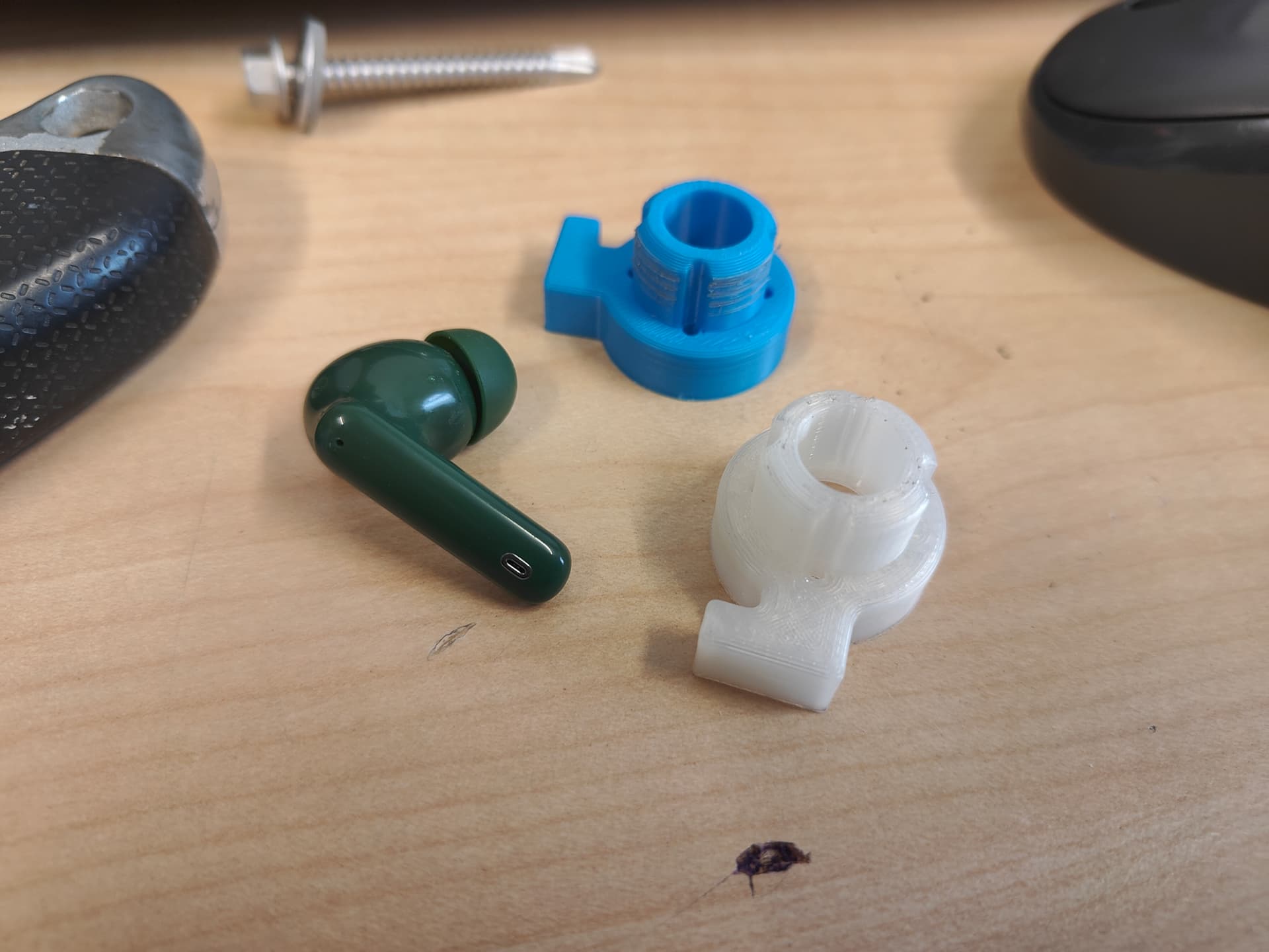
Small motors have small brushes and when you run them 100% above their maximum rating they can get a little sad. Pulling the ends off the RB-130’s I found the answers to my questions. Chunks of The Material Formerly Known As Carbon were spattered on the commutator which some sooty build up and general arc-ey glassy residue in strong attendance for a relatively tiny space.
My theoretical breakdown is with the higher voltage and the stalling, even current limiting wasn’t saving them and they were just becoming sad. This burning and coating of the com’s was making it hard to pick up and start the motor, it would just flood and current limit immediately - or make the other motor work harder to overcome.
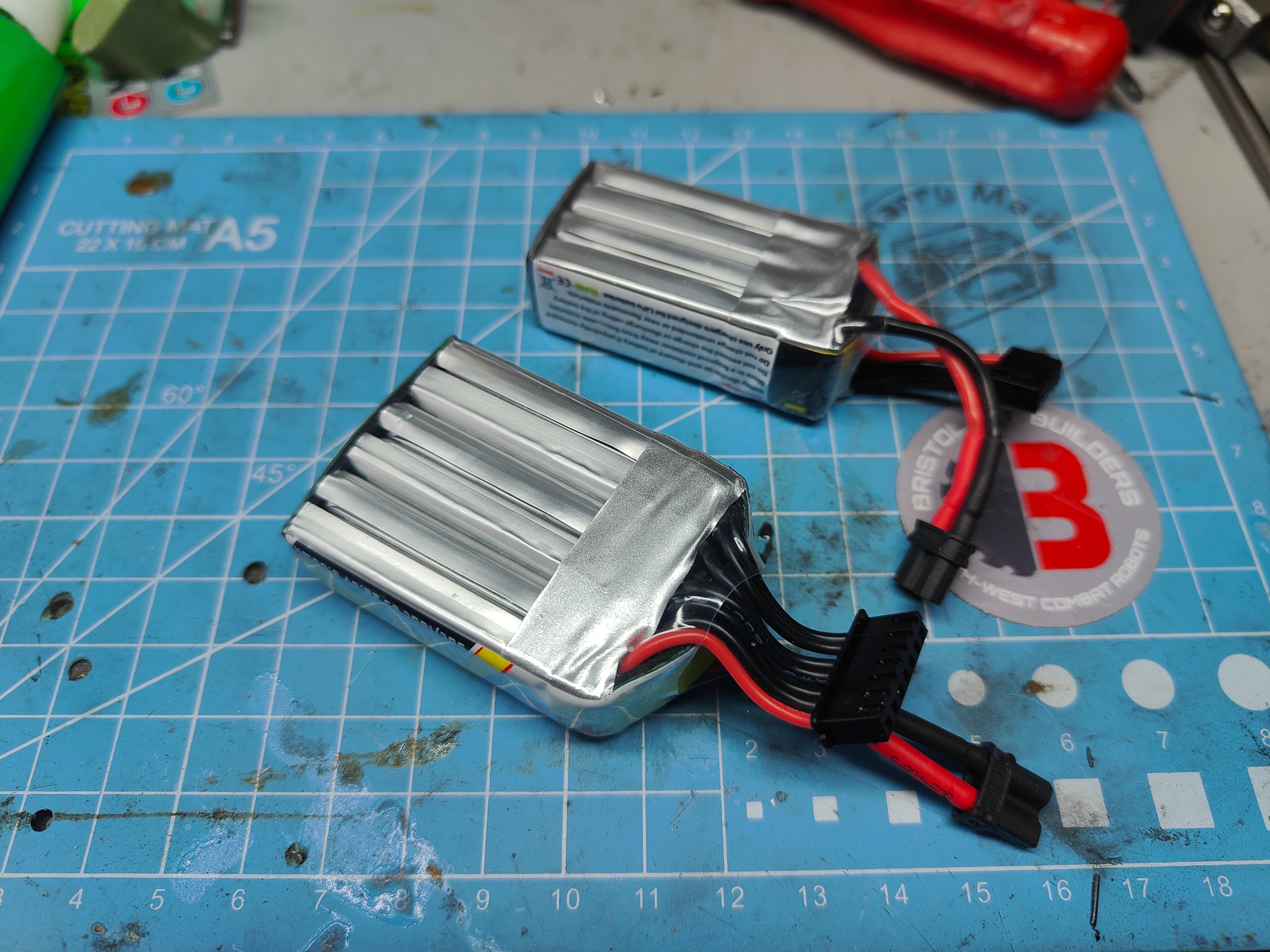
This fits with why the motors worked on a battery as you could just dump current into it until Fetch Happened. I cleaned the coms up (thanks vintage RC car racing!) and the clouds lifted. It worked as it should - not wishing to run into a silly issue on the day I simply ordered and fitted two new RB130’s with the two OG’s being put into spares.
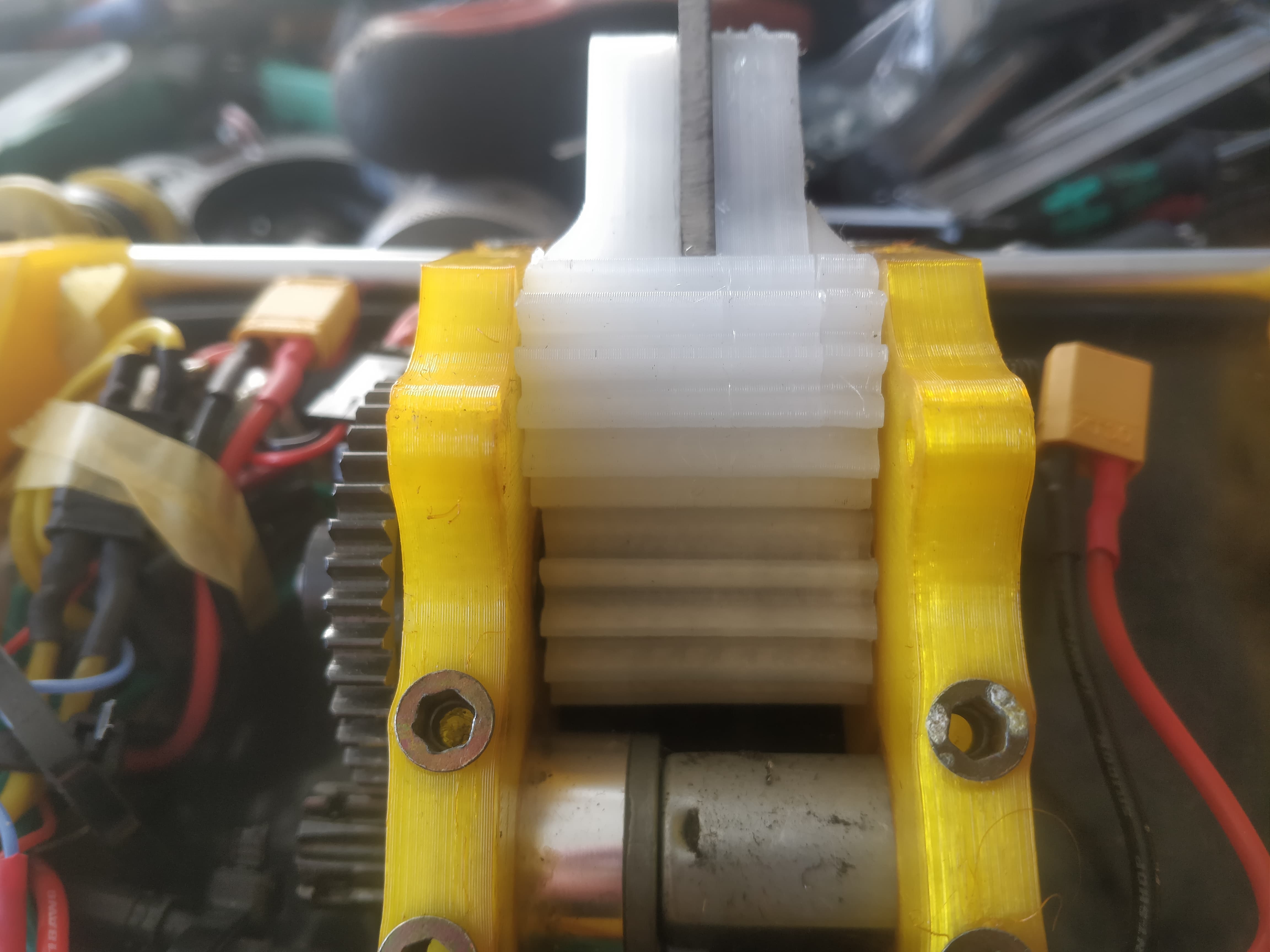
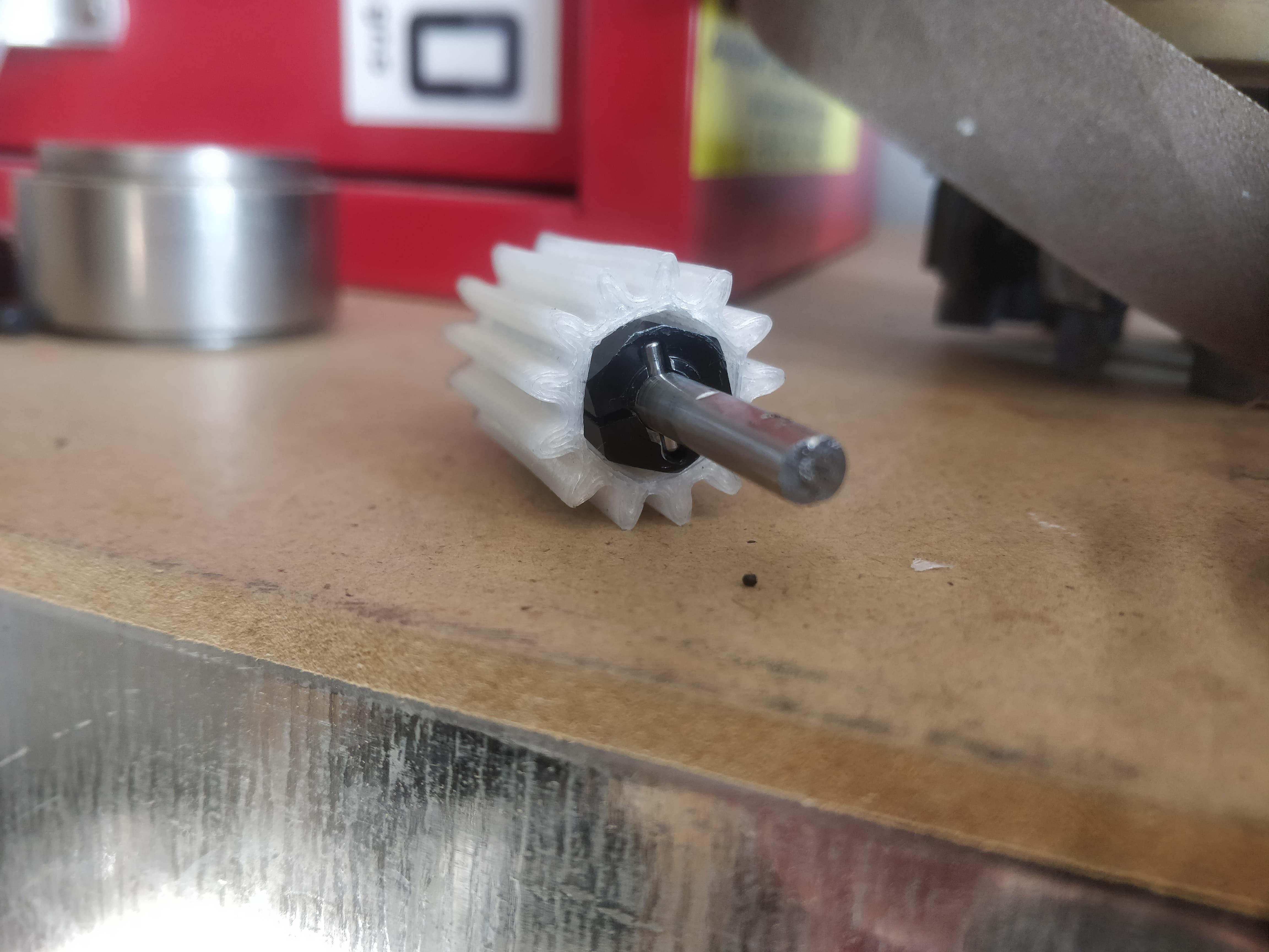
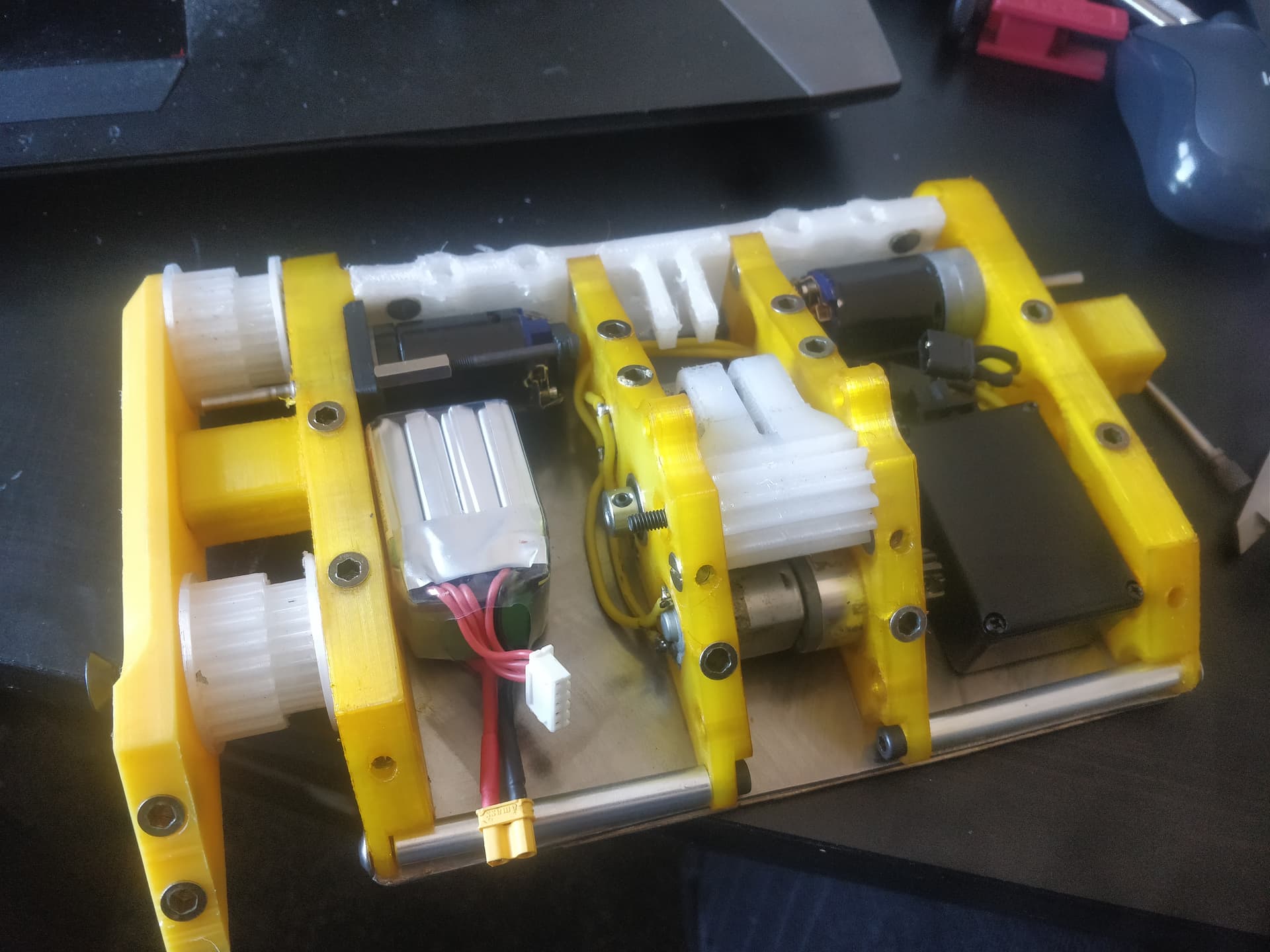
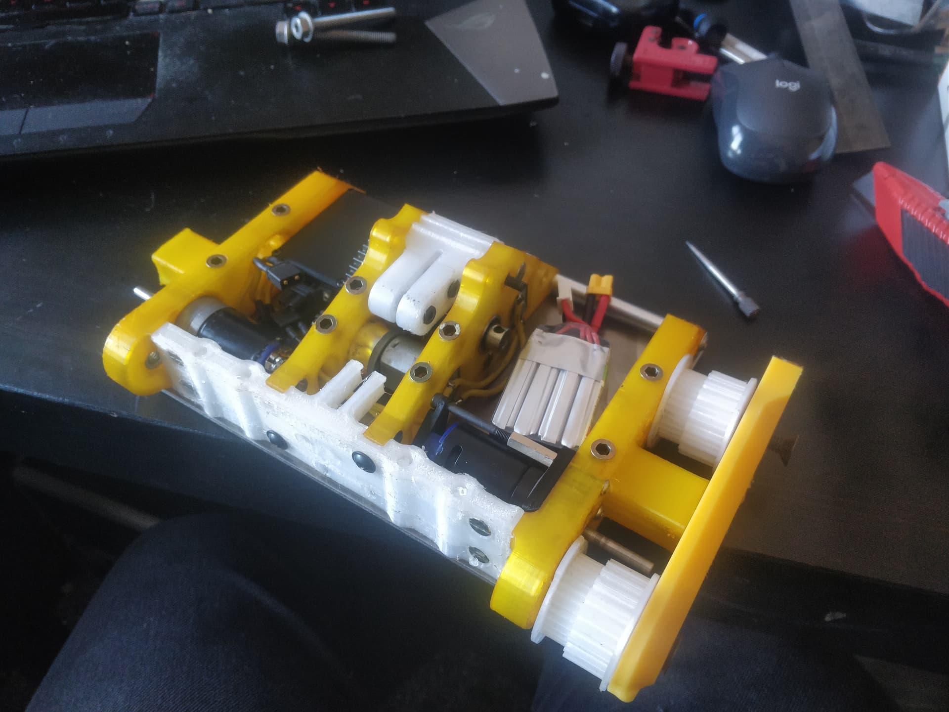
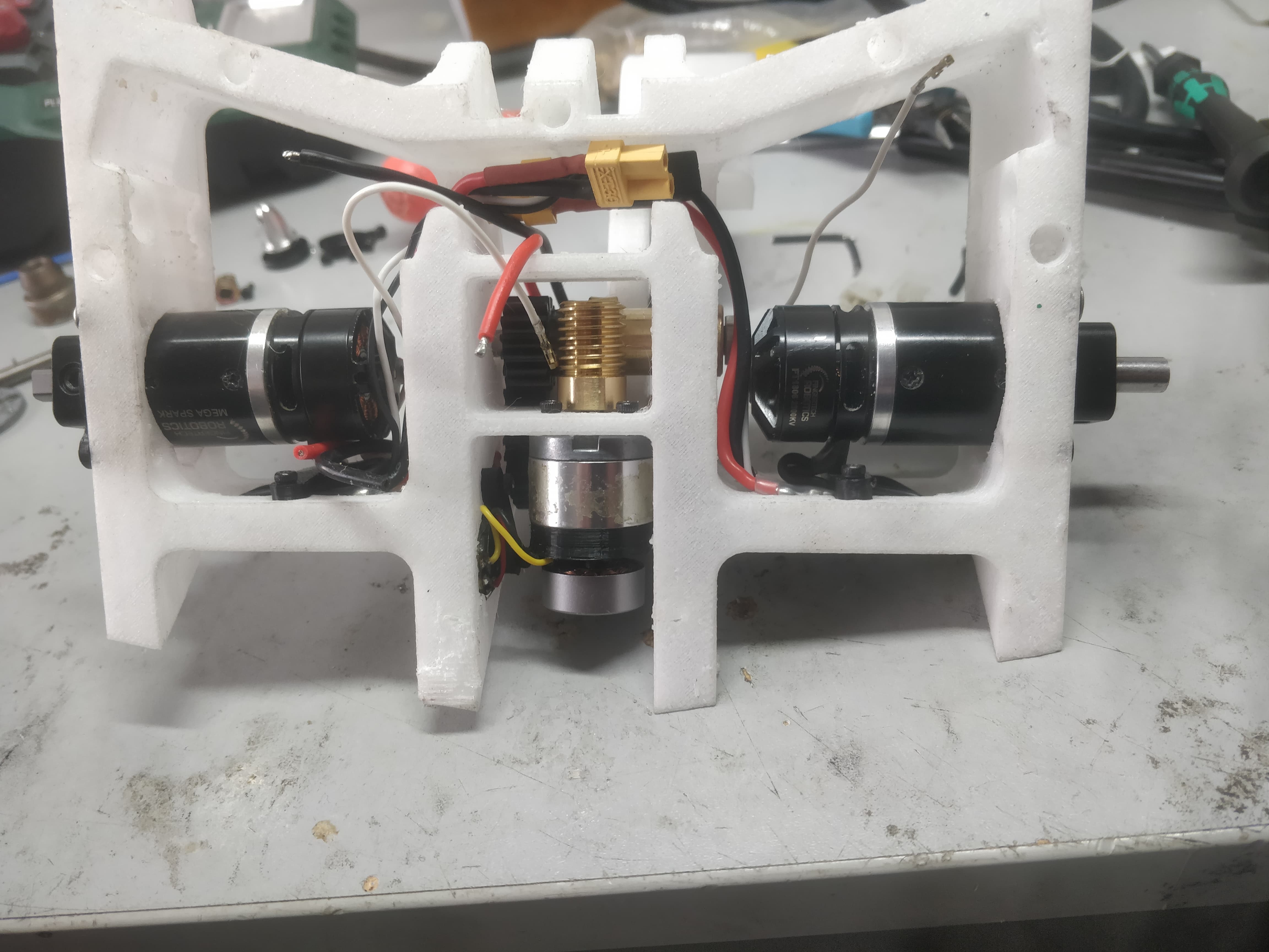
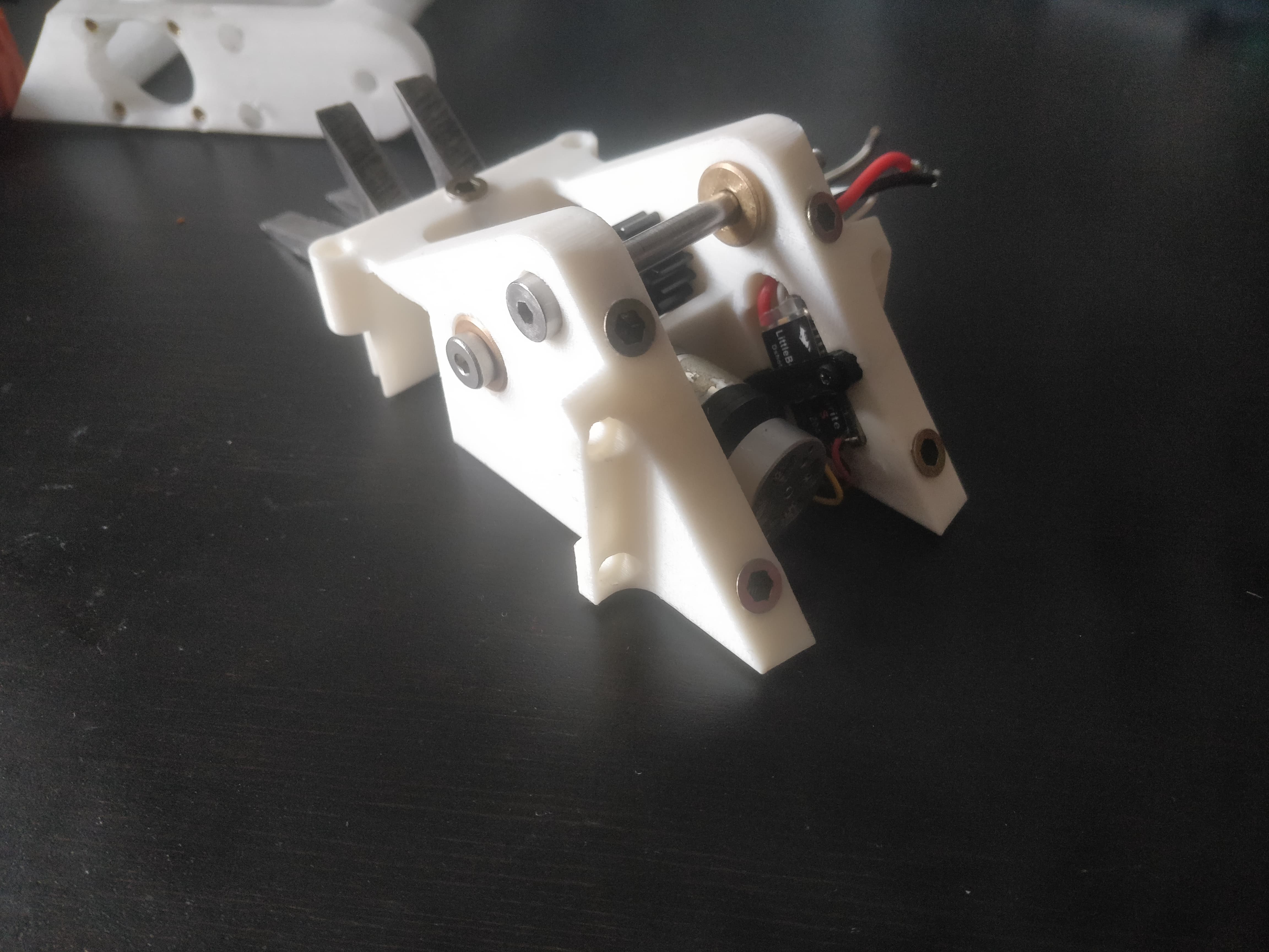
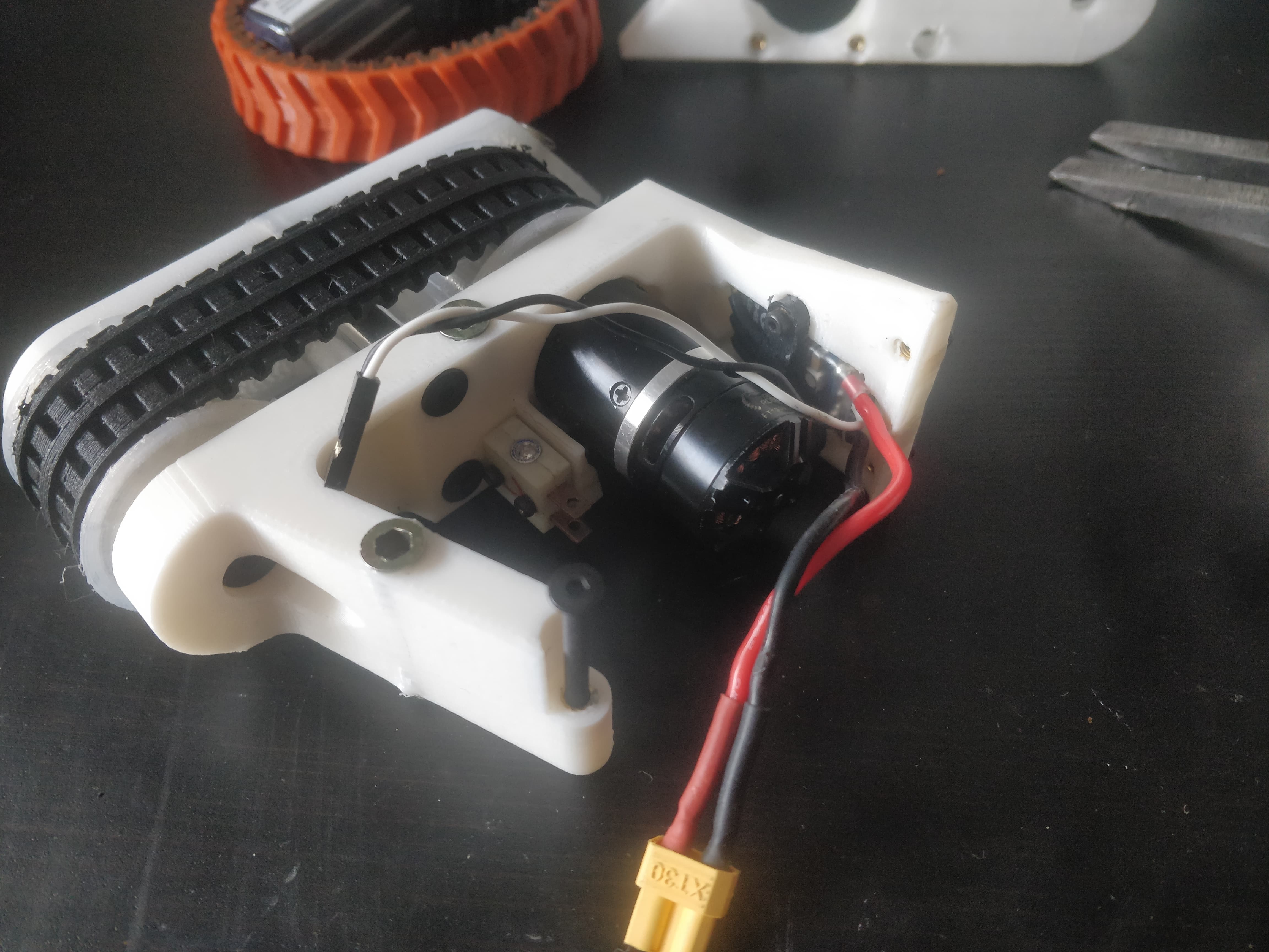
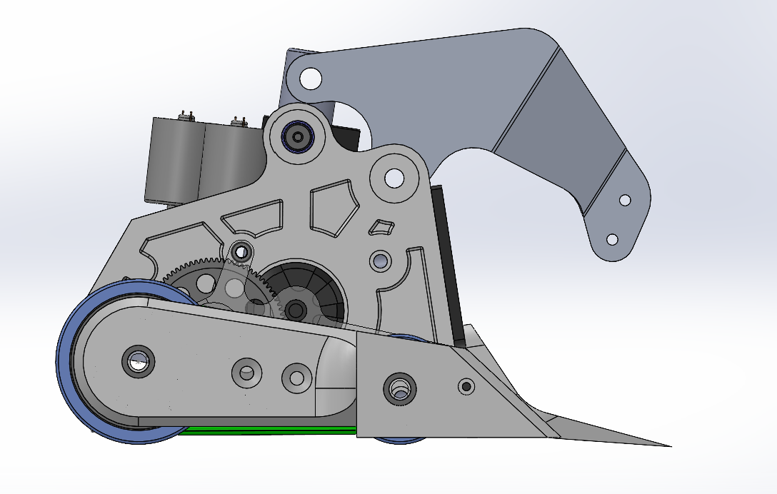
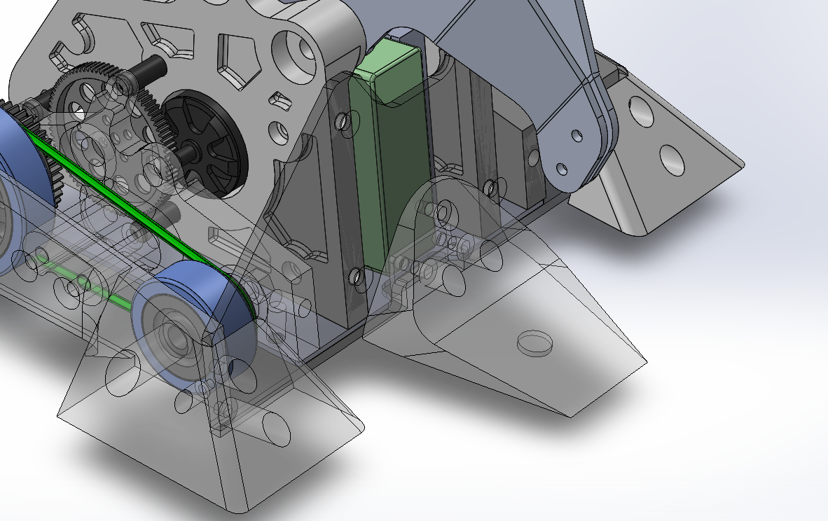
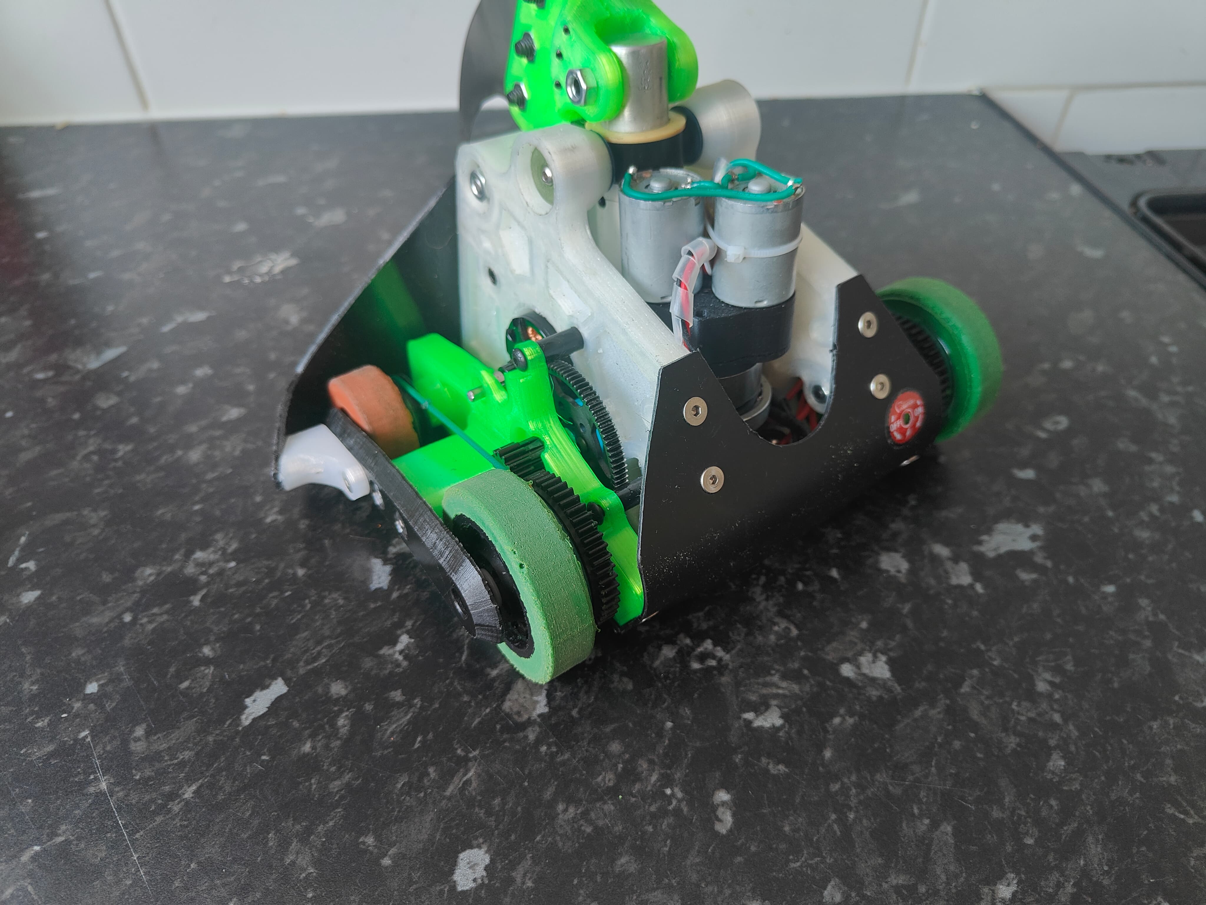
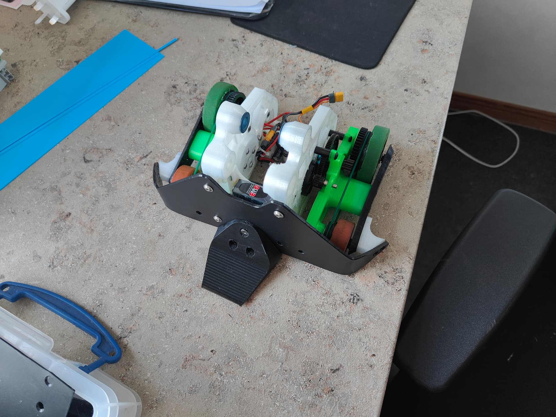
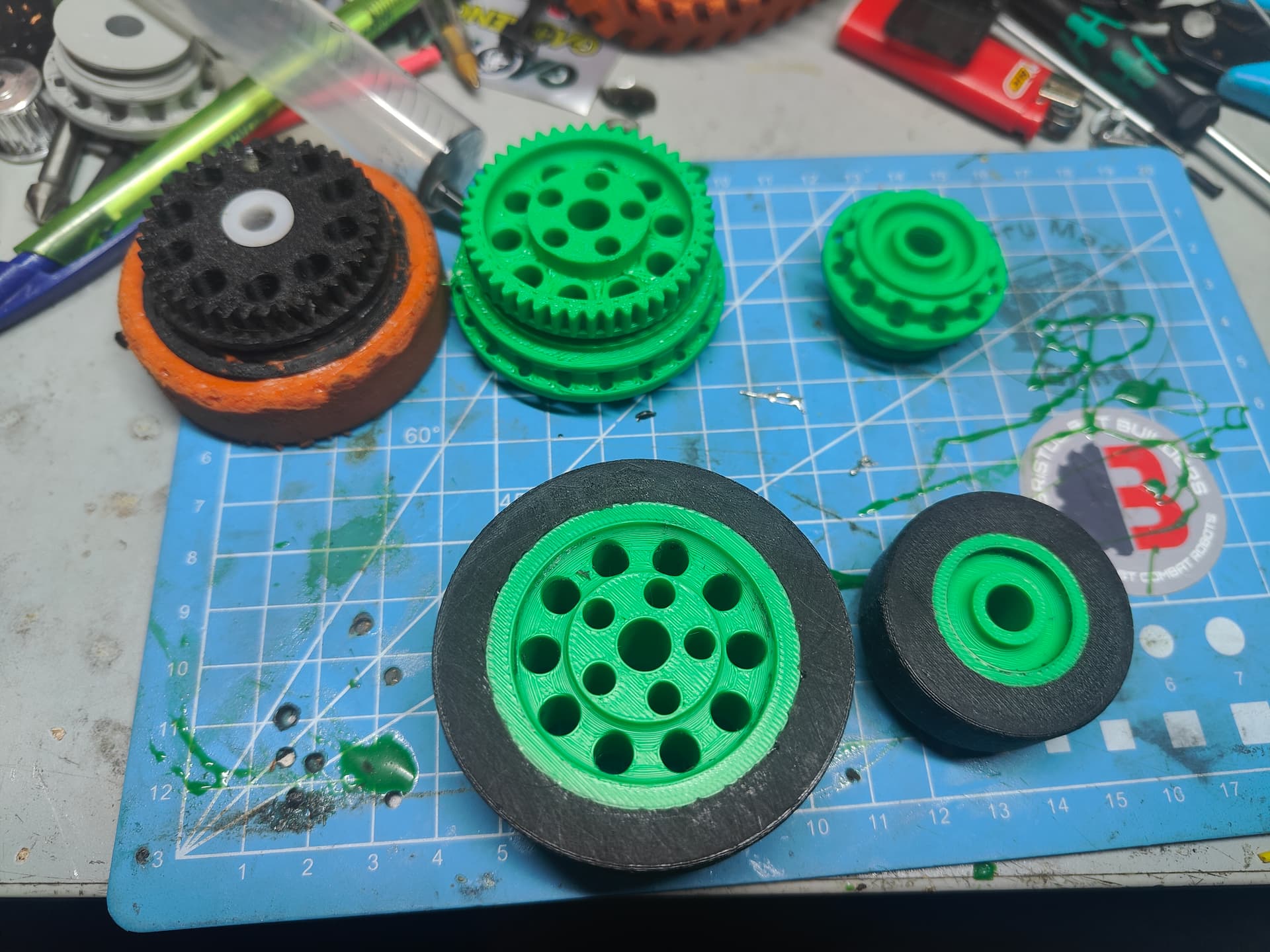
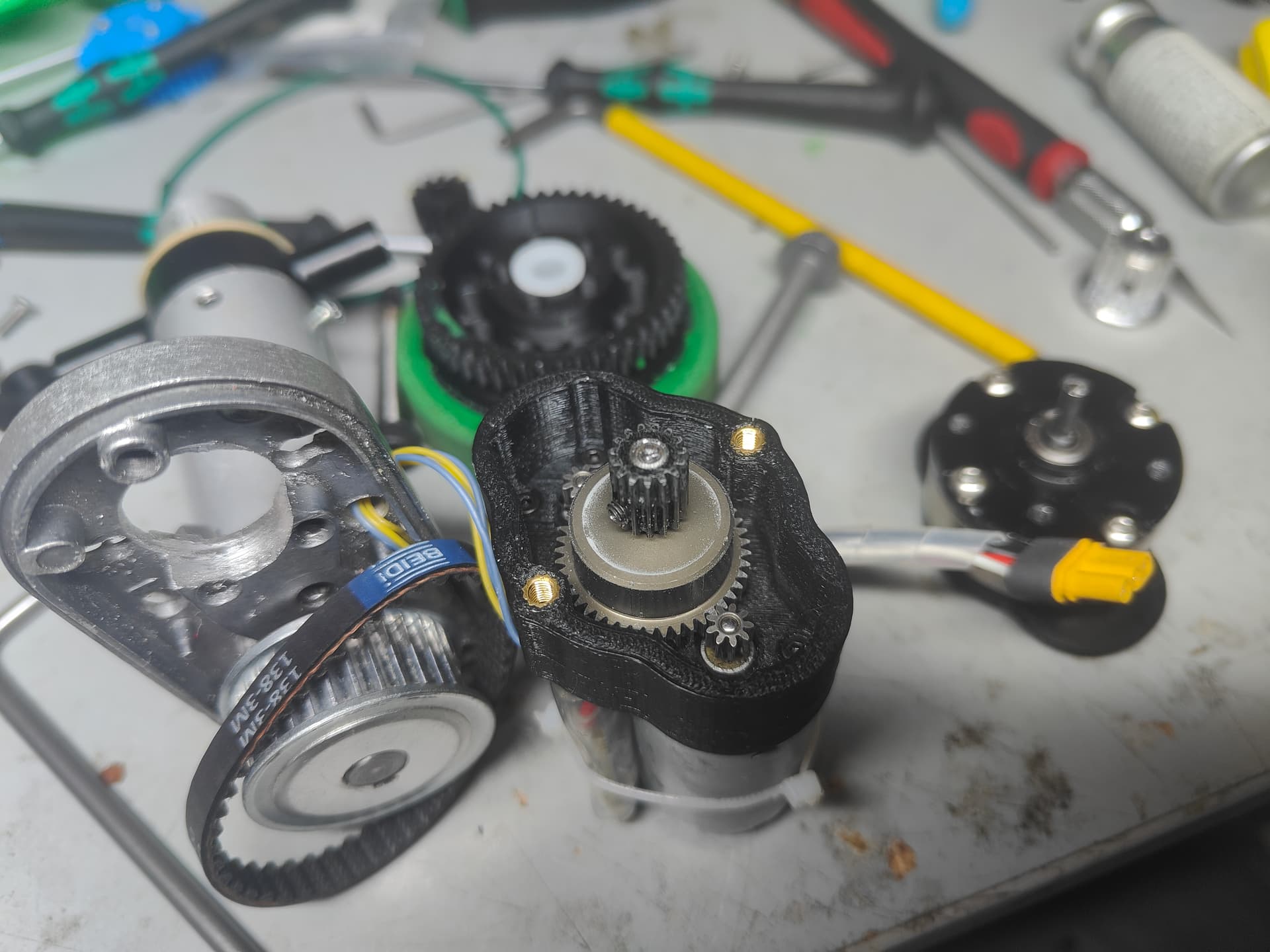
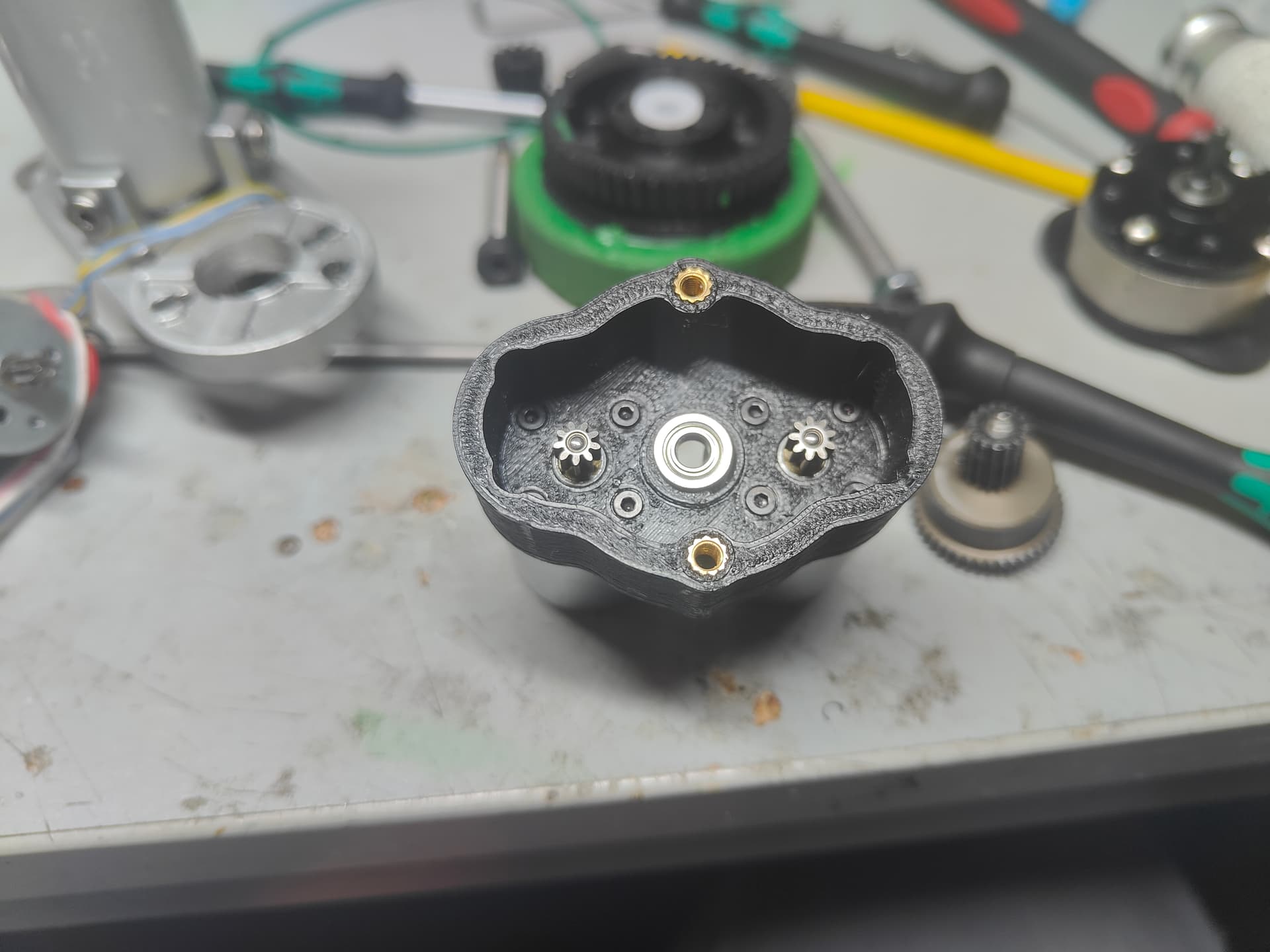
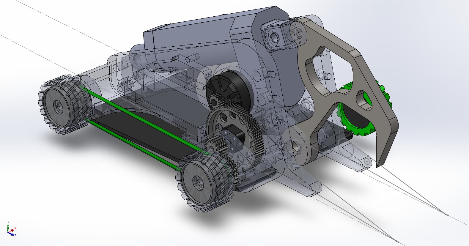
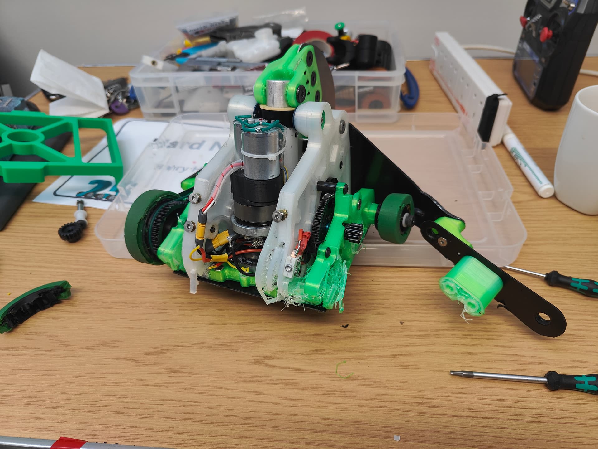
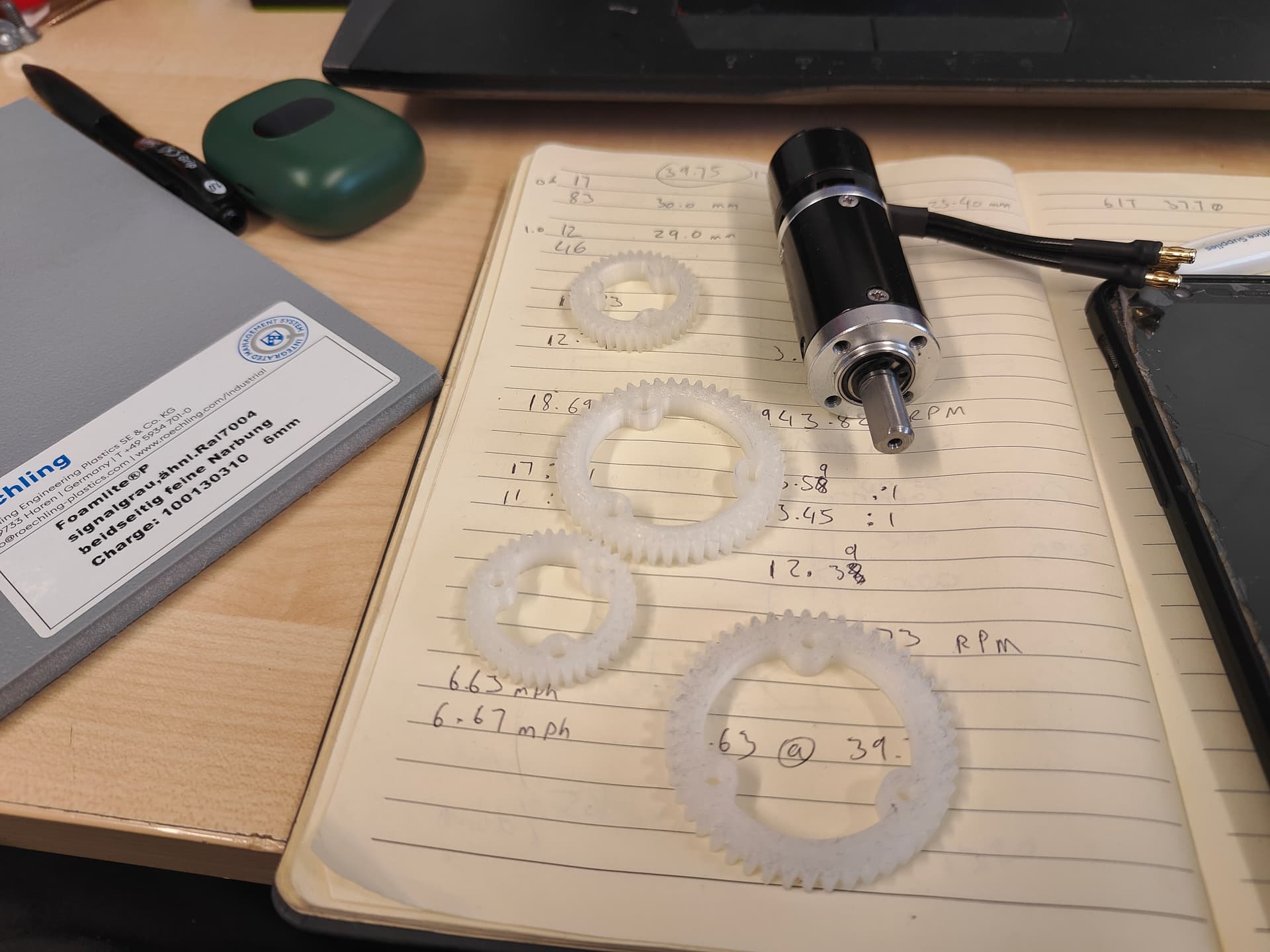
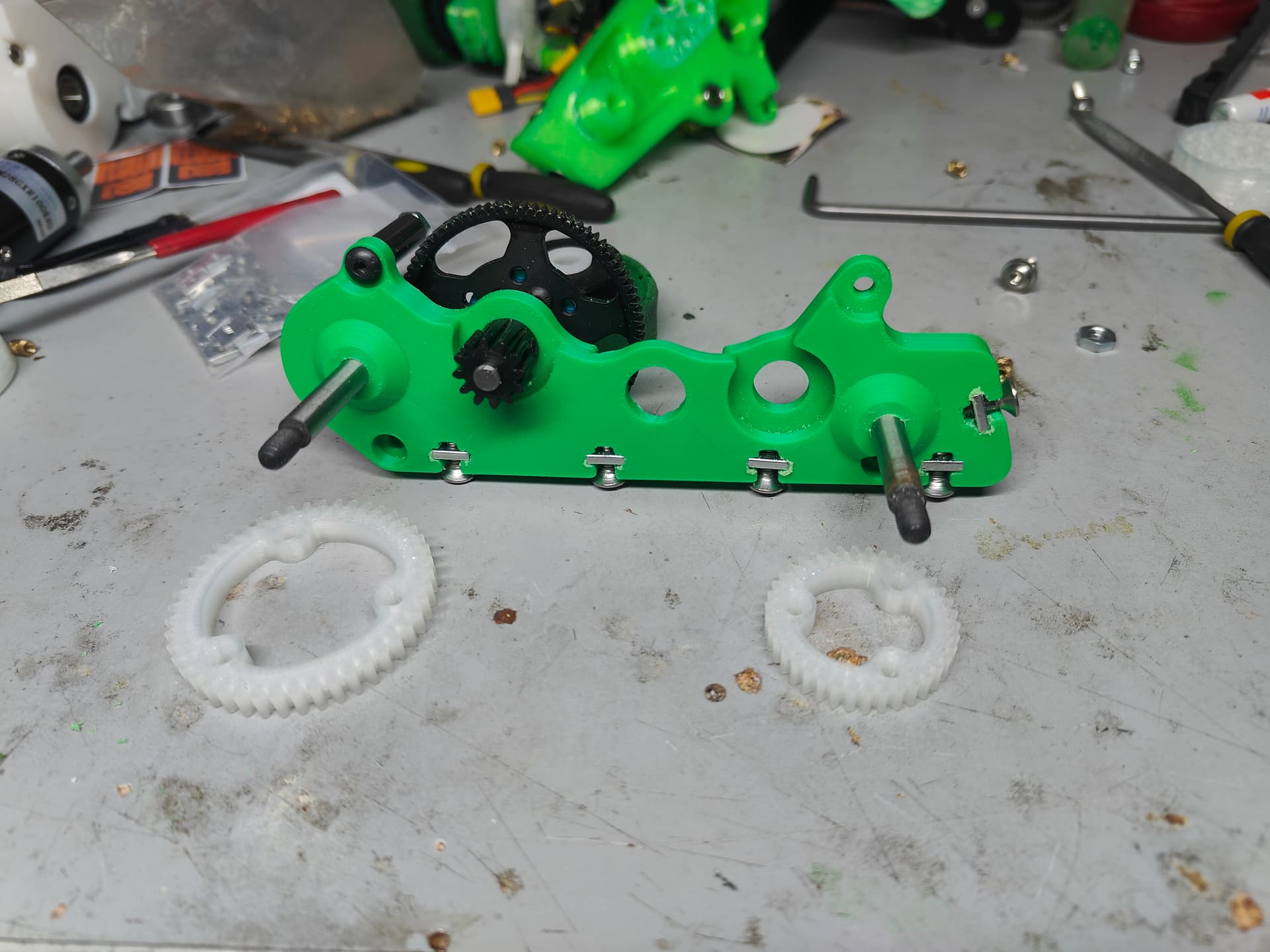
I took the opportunity to strip and re-grease the gearbox housing as I don’t think I took any pictures on the initial assembly. It is really painfully simple just using the stock pinions into an RC car spur gear. There is a little flanged 1/8” bore bearing pressed in from the rear and the rest of the assembly is just supported by the RC planetary gearbox. The housing is ABS and it still has those sinful heatpress inserts (which are still holding well!)
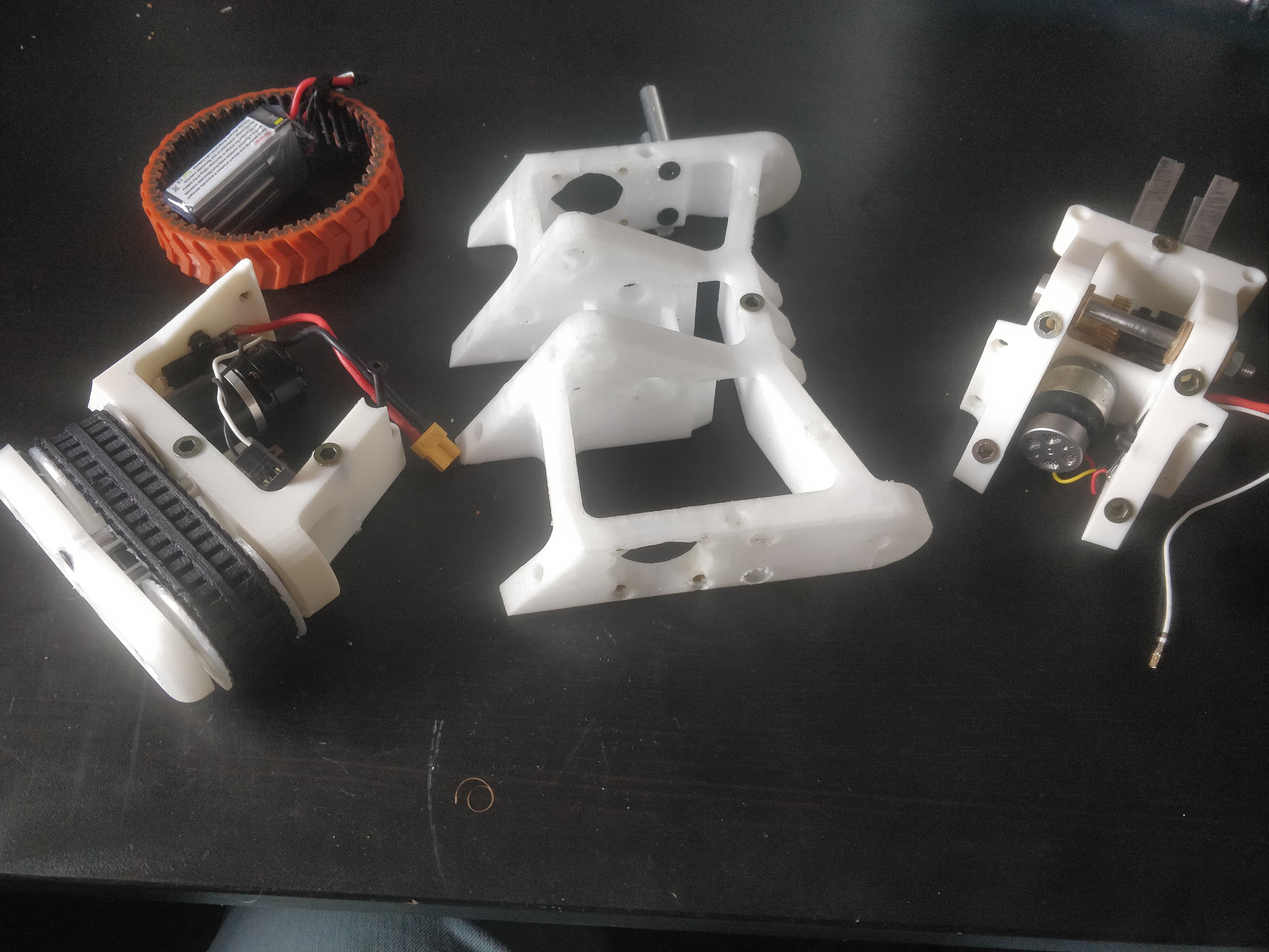
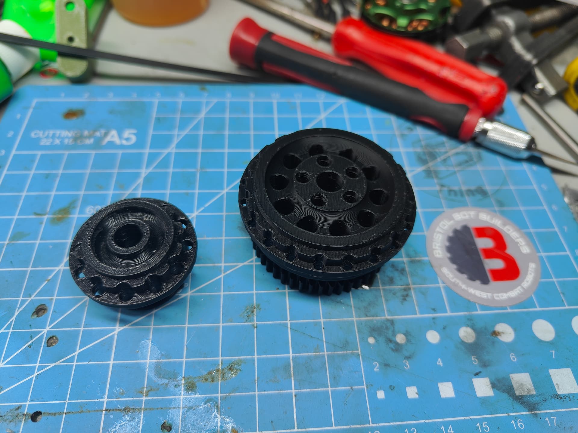
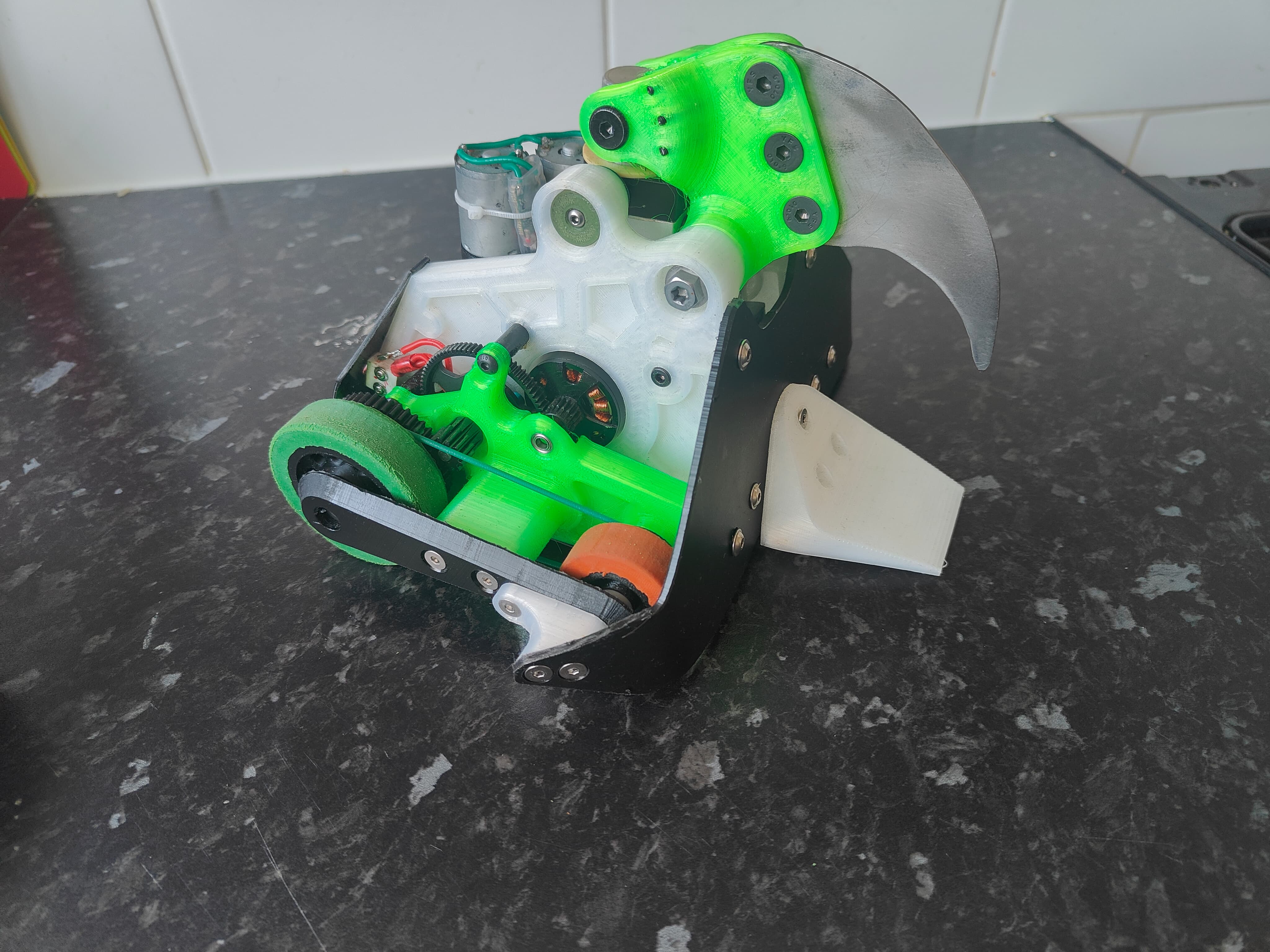
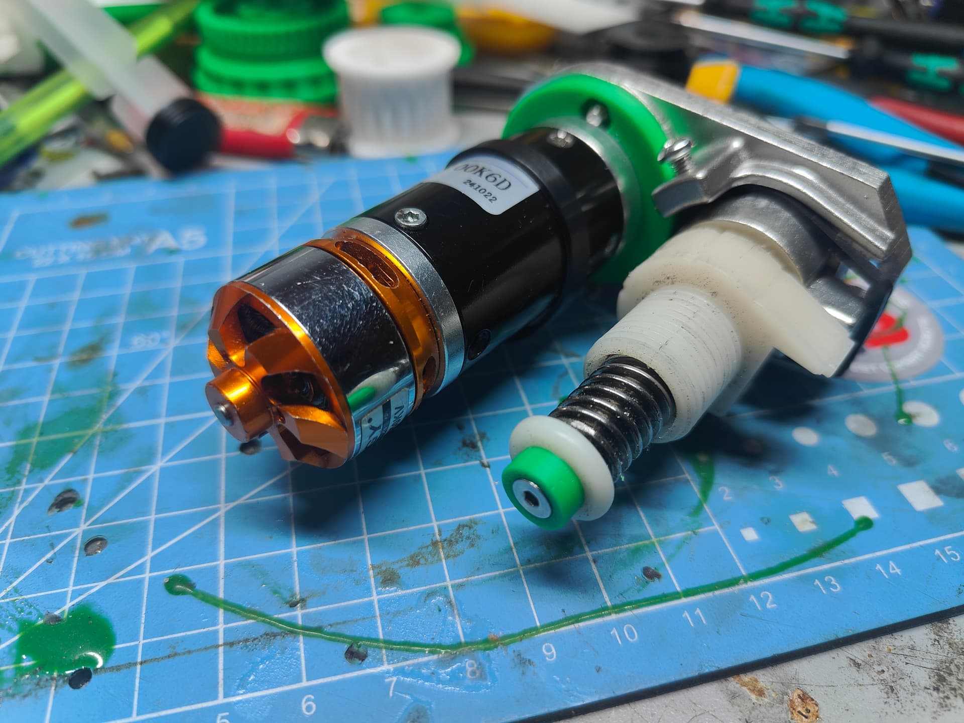
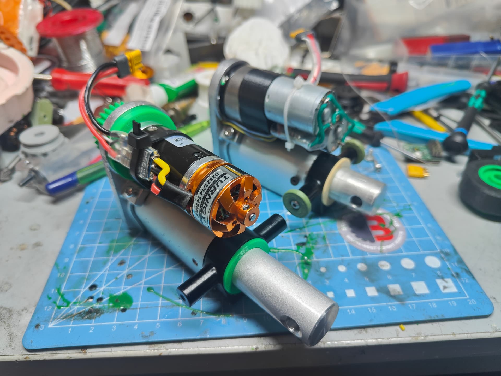
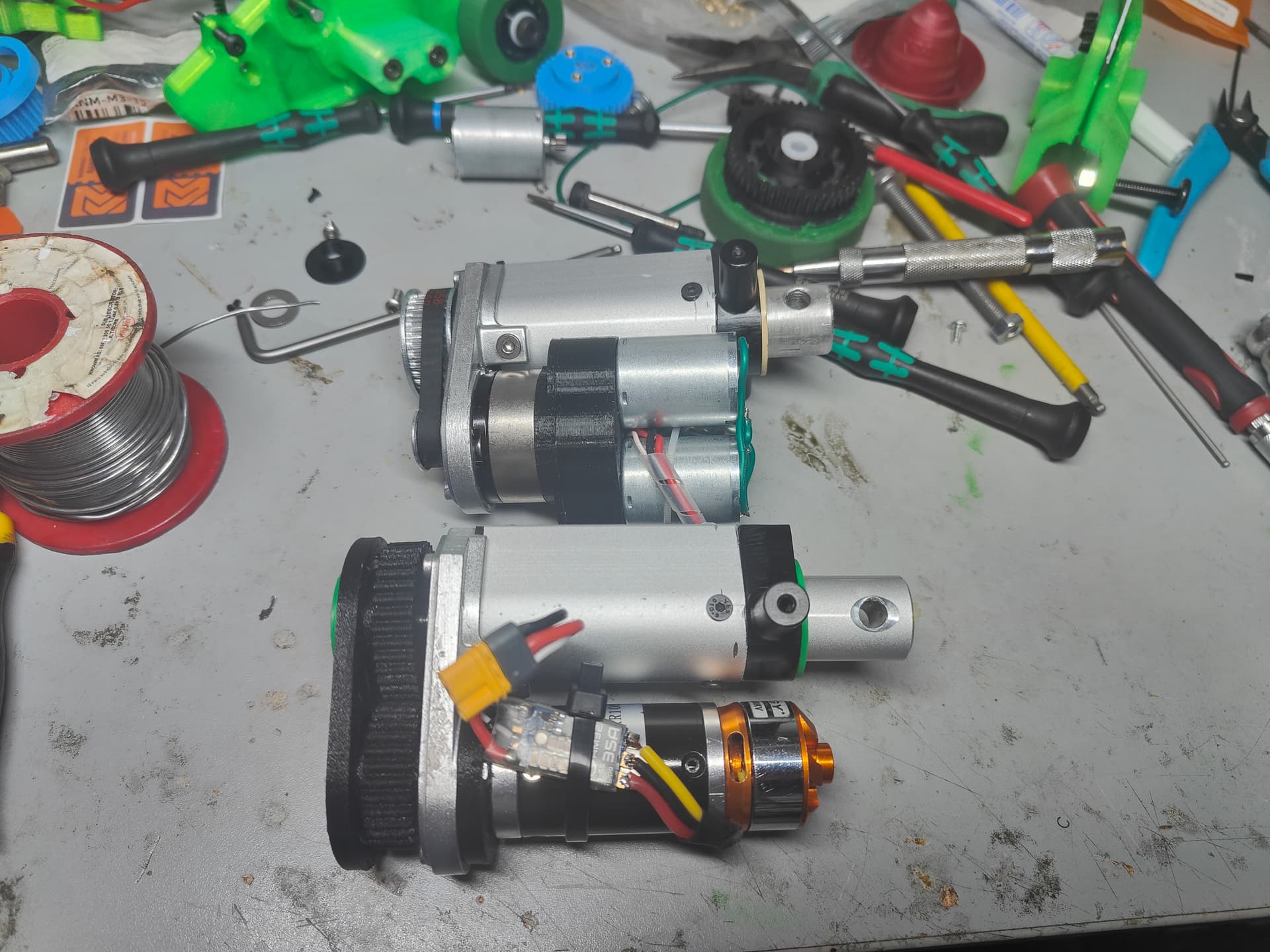
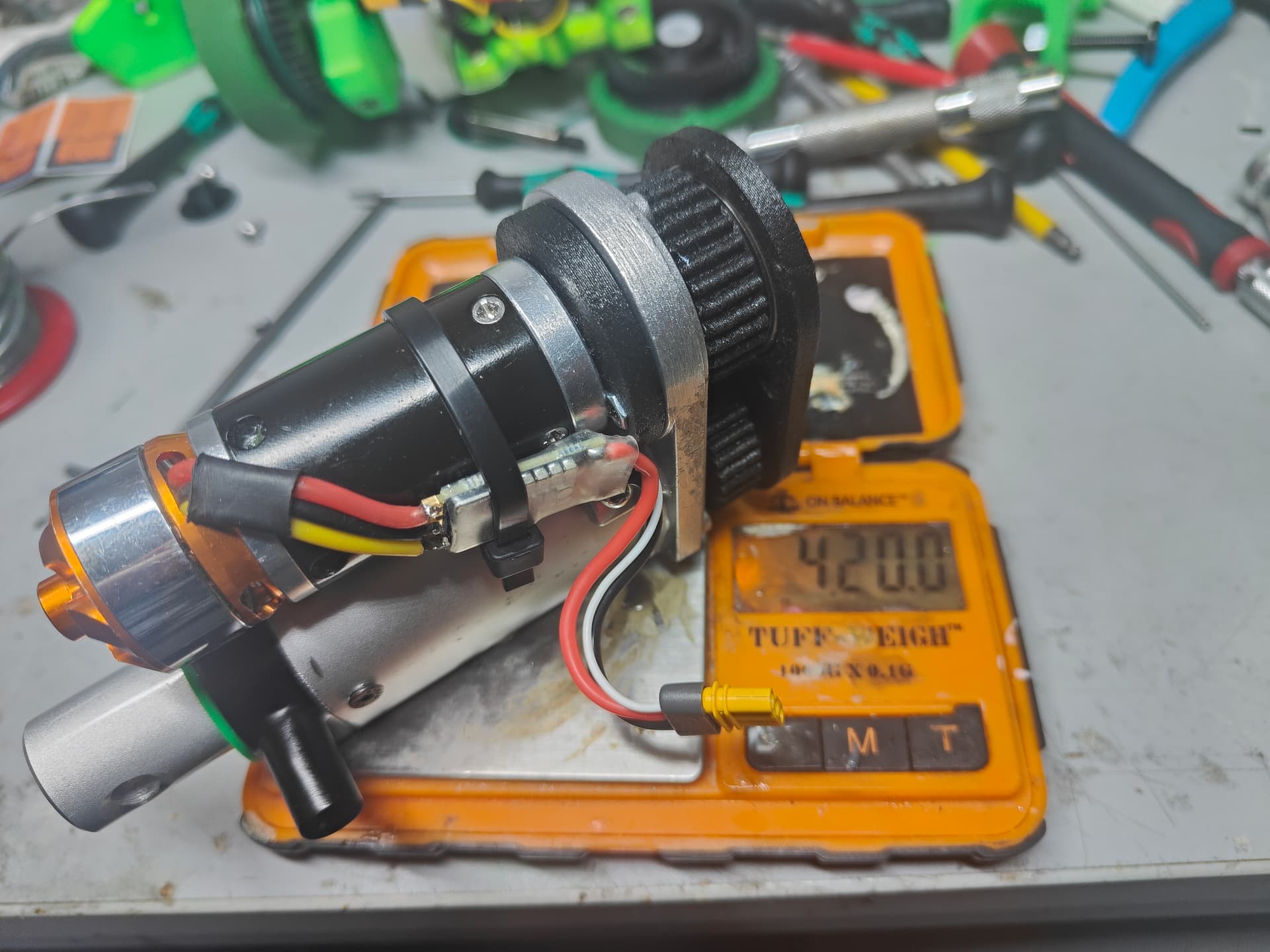
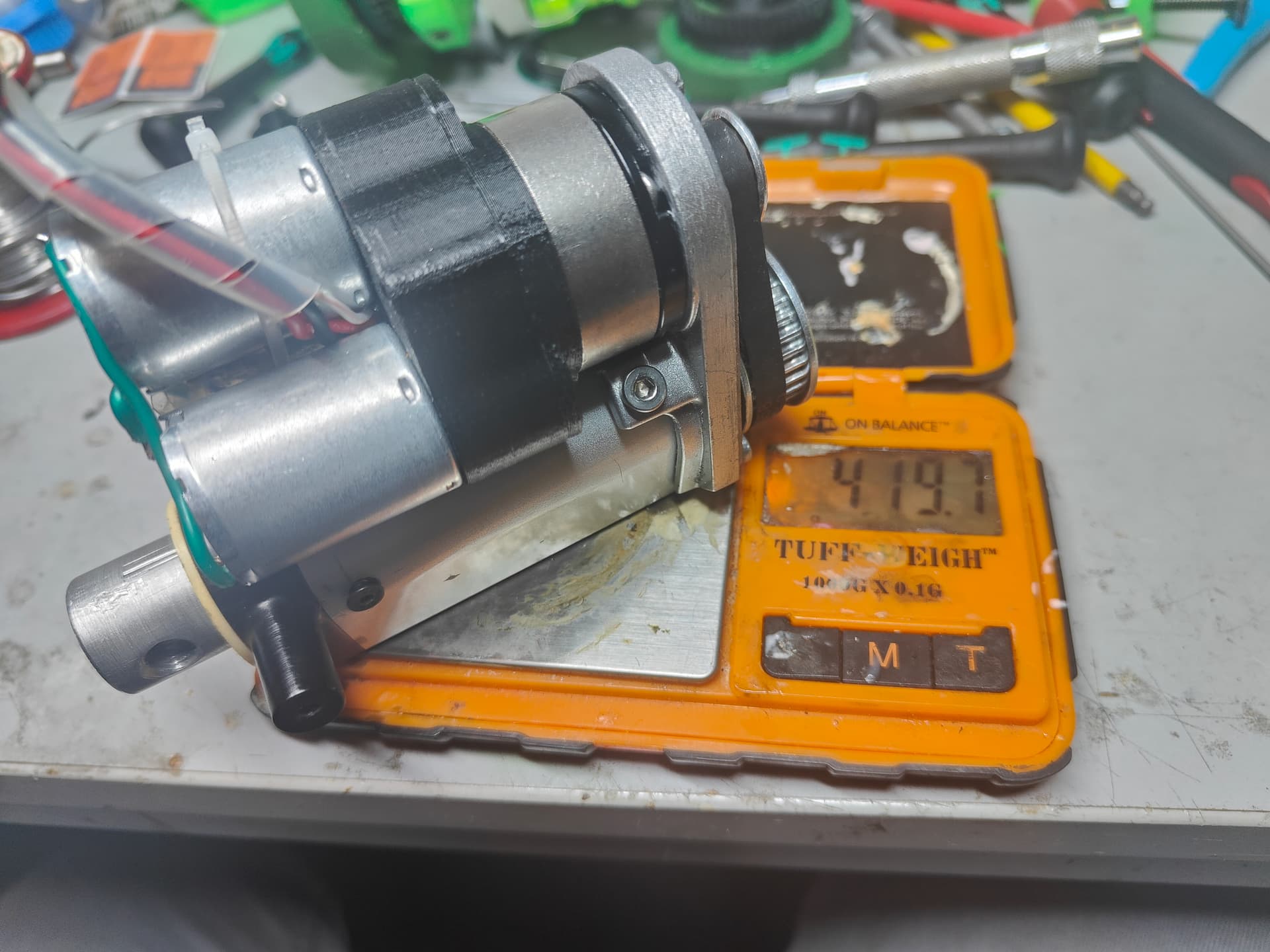
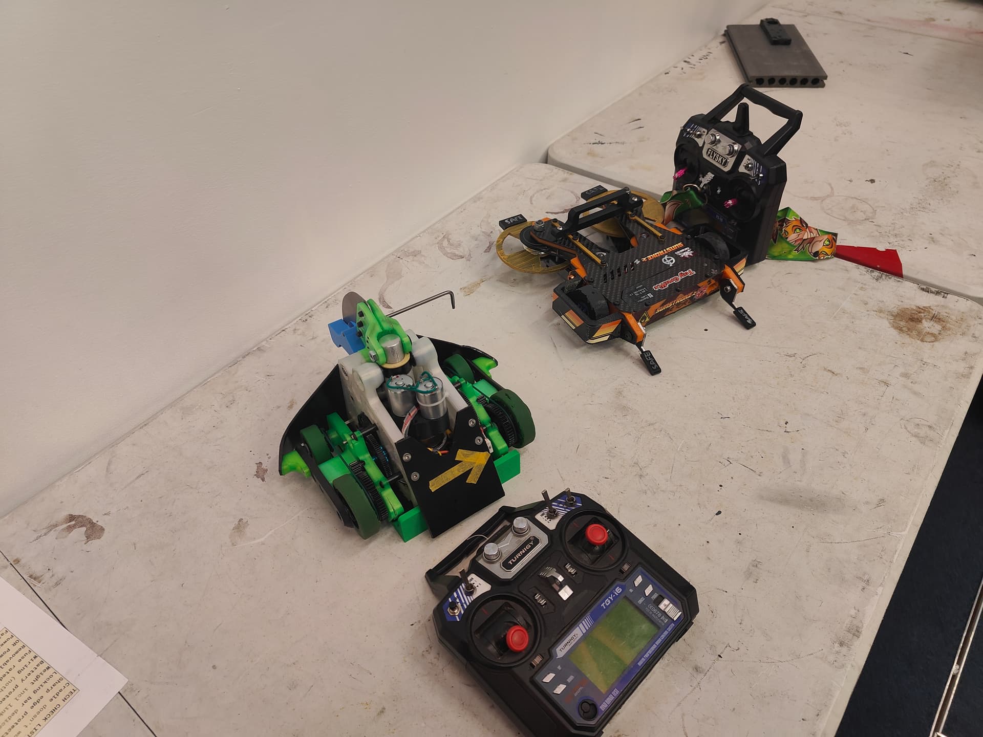
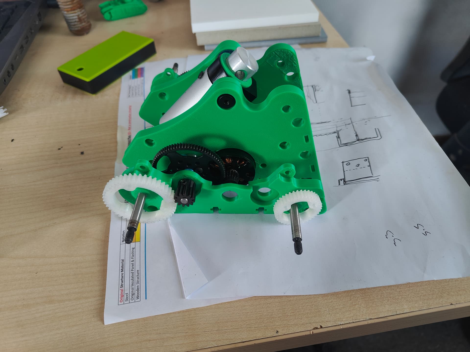
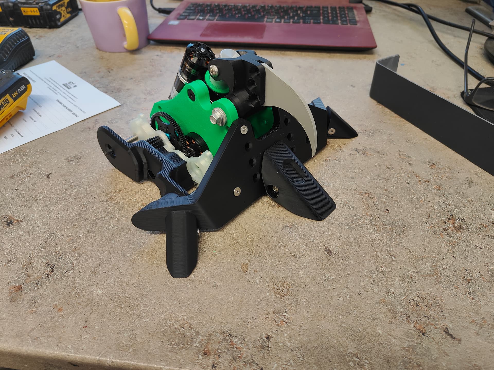
The two actuators side by side. Two very different approaches made many months apart. The second brushless one is honestly nicer despite its unbrilliant design, presumably because I knew what I was doing.
Amusingly and completely accidentally the two options are within 0.3g of each other! Couldn’t have done that if I tried. The brushless one is much more powerful from a gut feeling perspective and the fact there is no limiting involved. I was hesitant to put it in, despite it being the better option mostly because it didn’t have any endstops or anything to save itself electronically either.
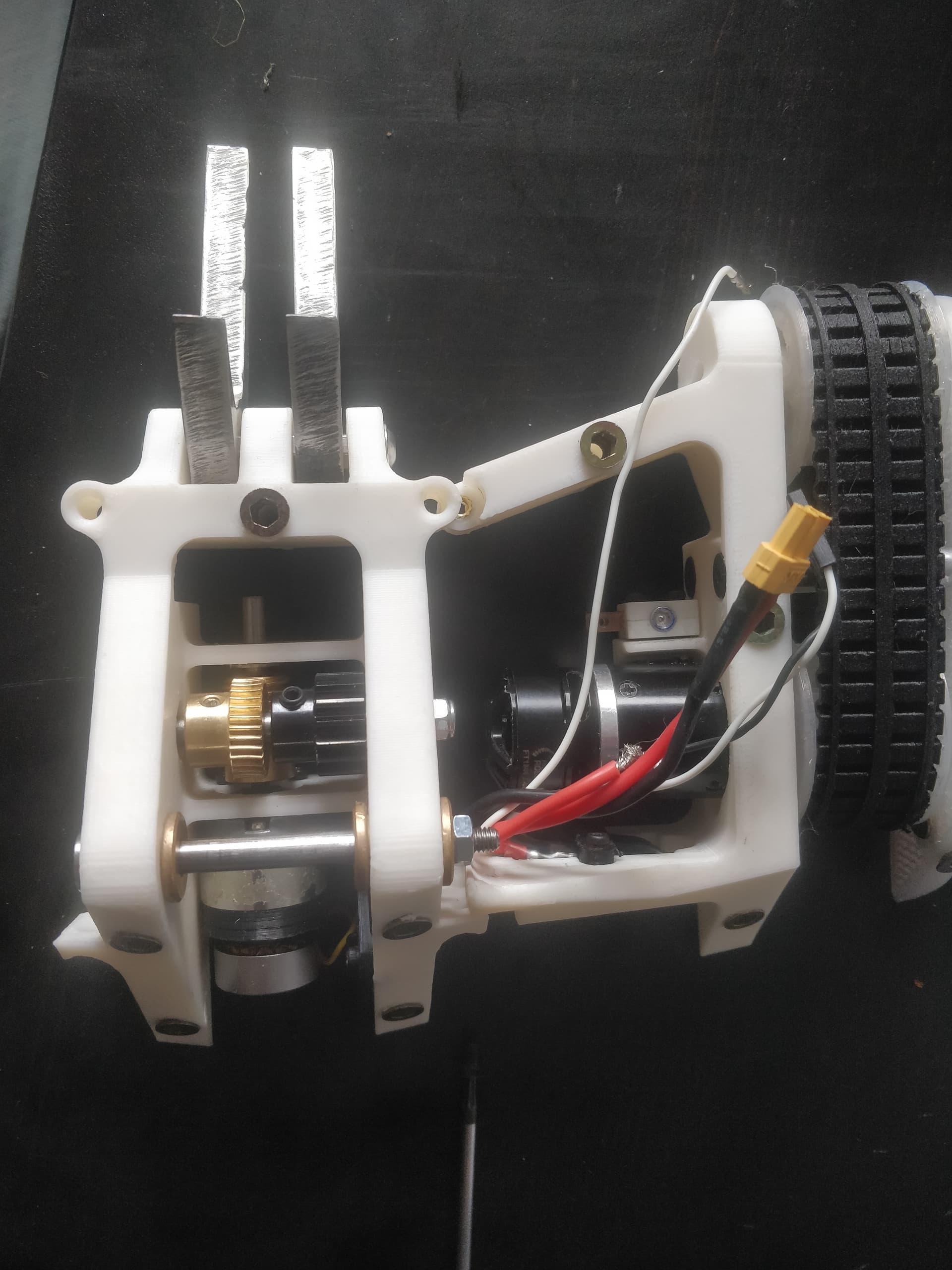
I stuck with this guy as that’s really what the robot is all about, it was designed around this one and I should get some use out of it. It’s a lot more set and forget. Plan was to switch out to the brushless purely as a spare.
With all systems being go I tried out Mr Nips and got an awful lot of nothing - RX had just upped and died. Something must have shorted out somewhere - even the 4 for a tenner aliexpress bad boys I use aren’t that bad. Nothing was apparent but I did find it a little gruelling to have to take everything apart to get in and swap it for a new one and just check the Repeat Dual is still happy.
Gee golly I hope I don’t have to work on this under pressure at the event.
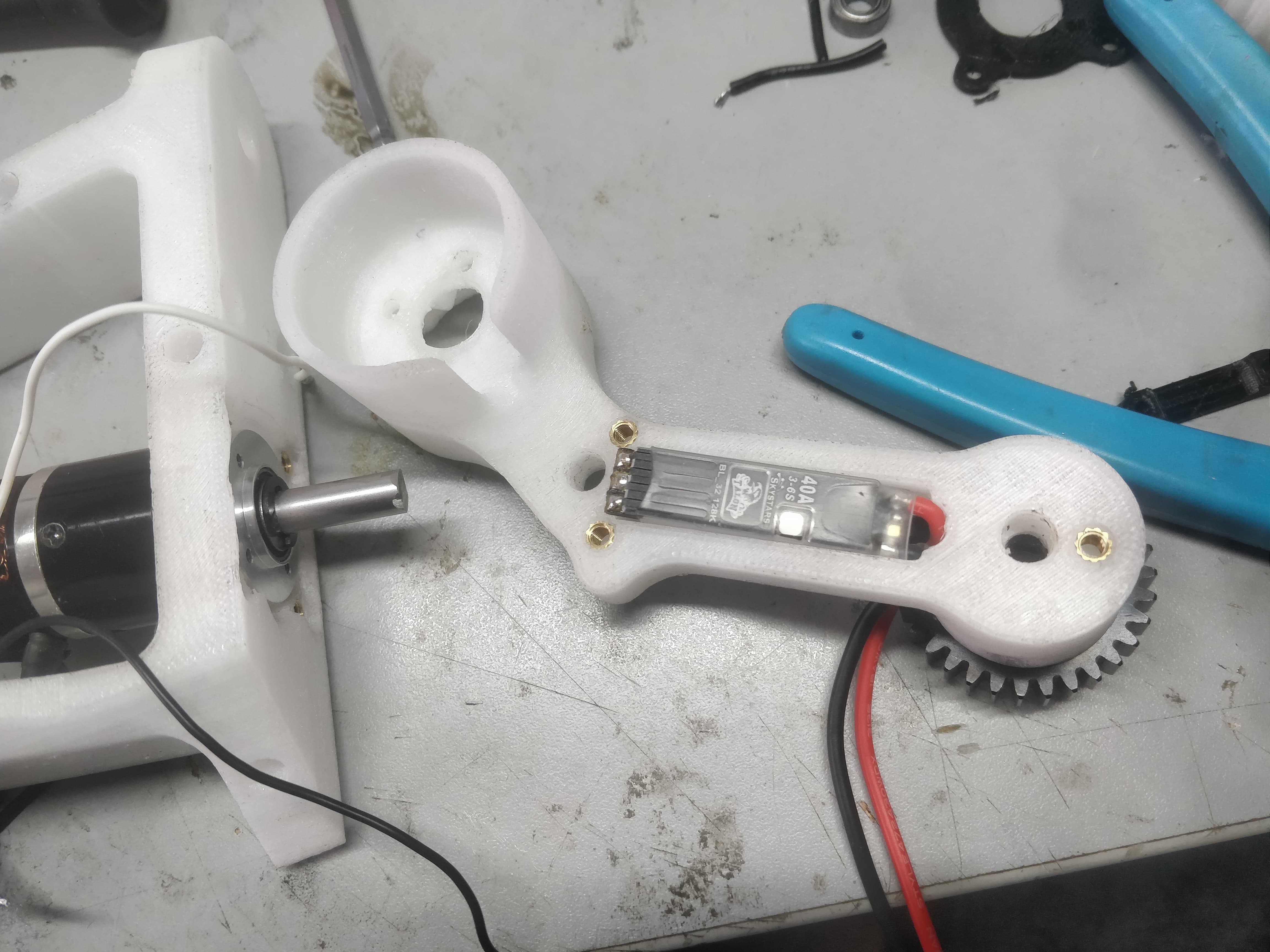
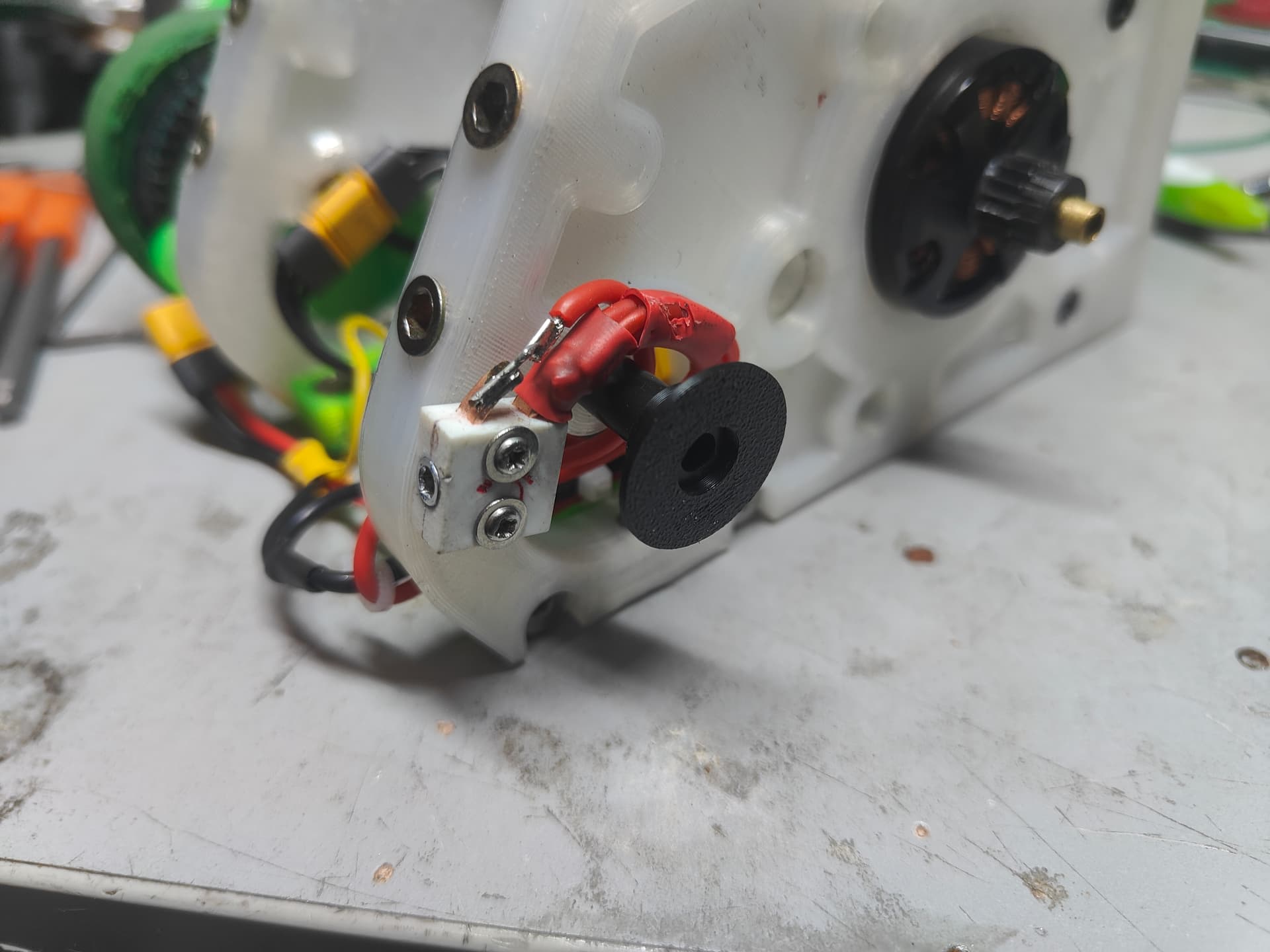
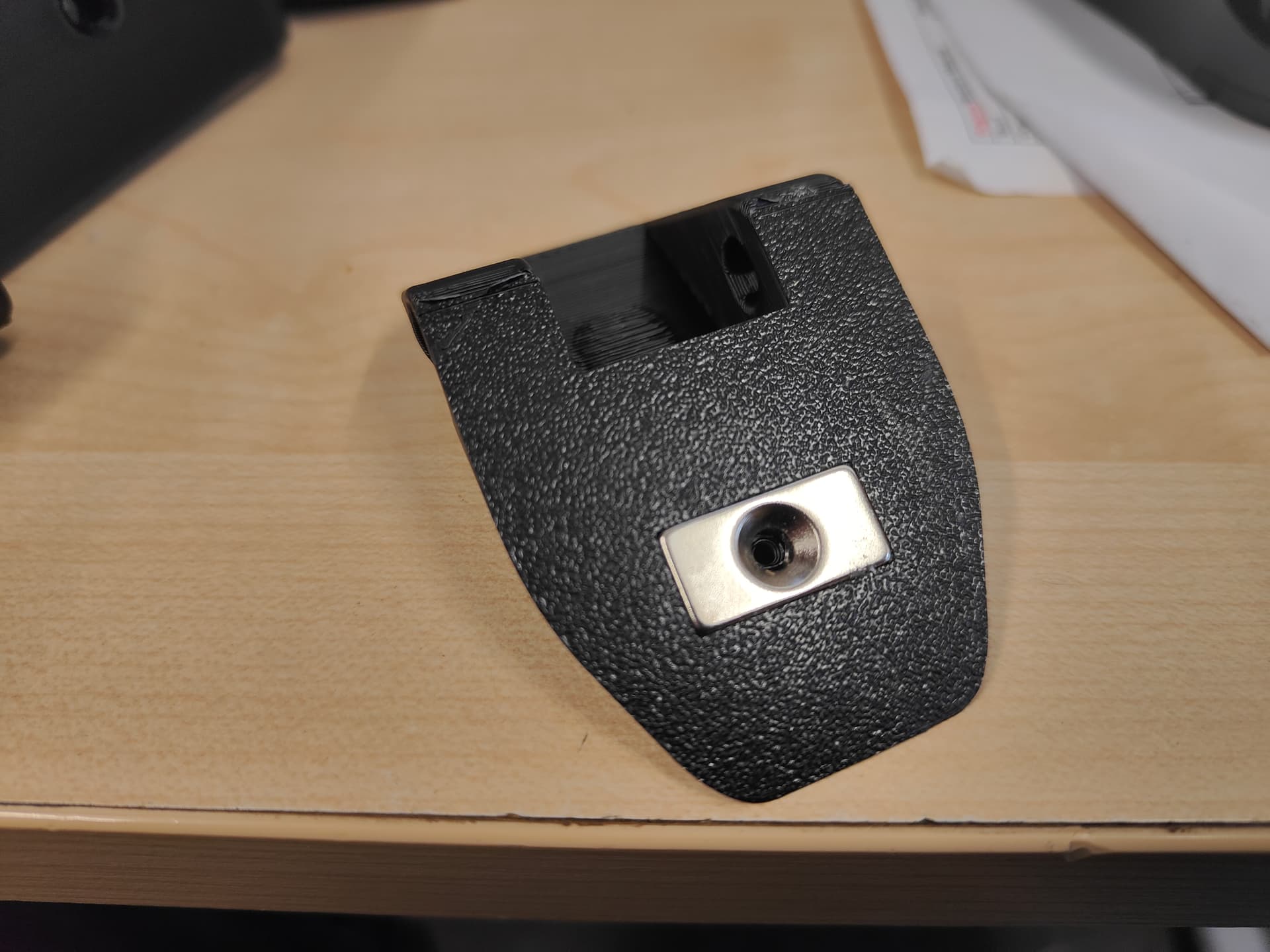
As a last minute addition I made myself a little ABS tophat washer which keeps the spur away from the switch wiring. Those of you with working eyes can see the first layer of heatshrink had been gently mulched over time. It just span on the existing nylon standoff.
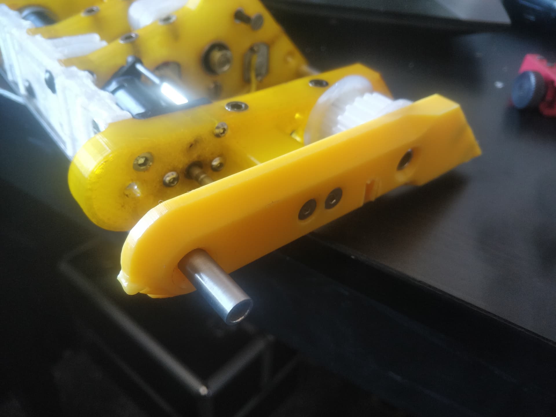
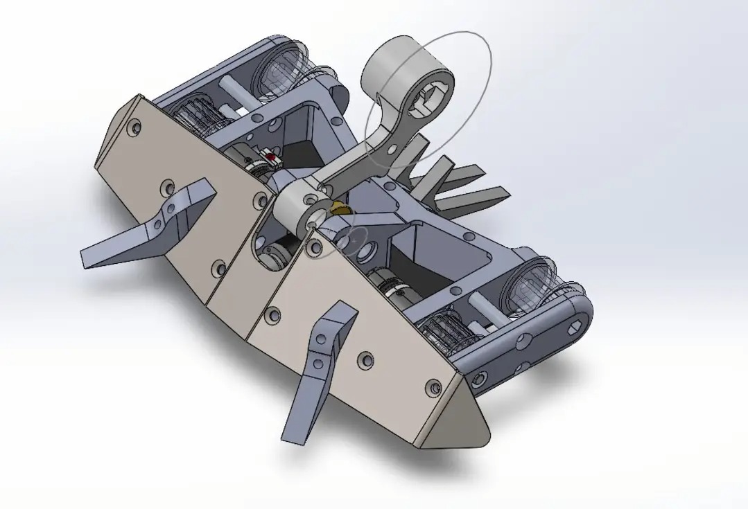
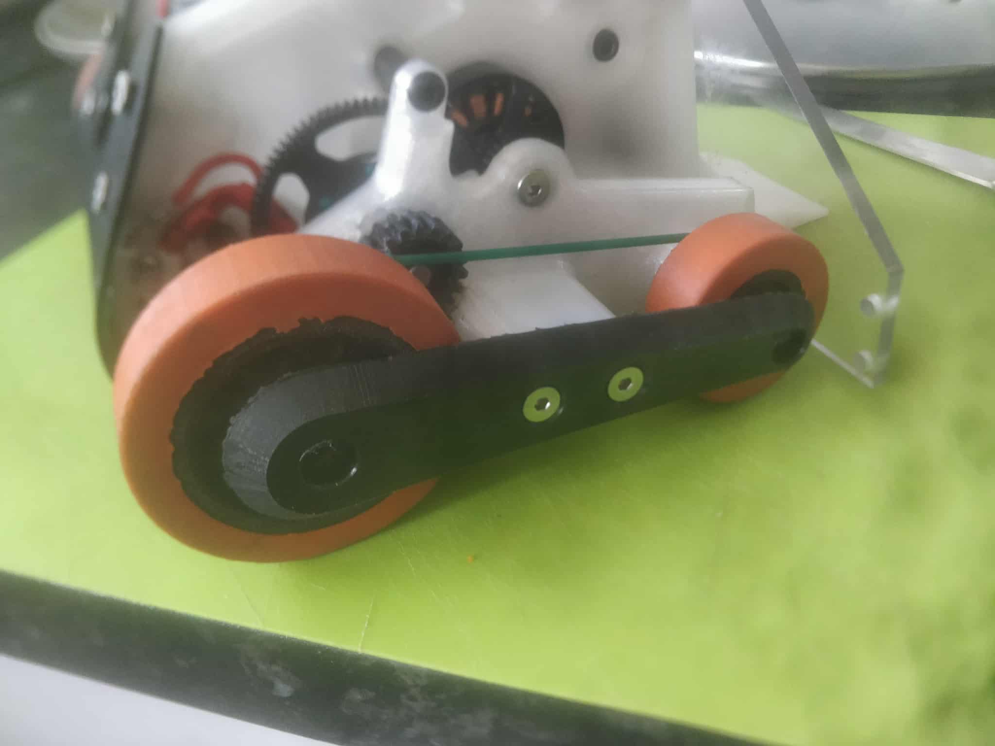
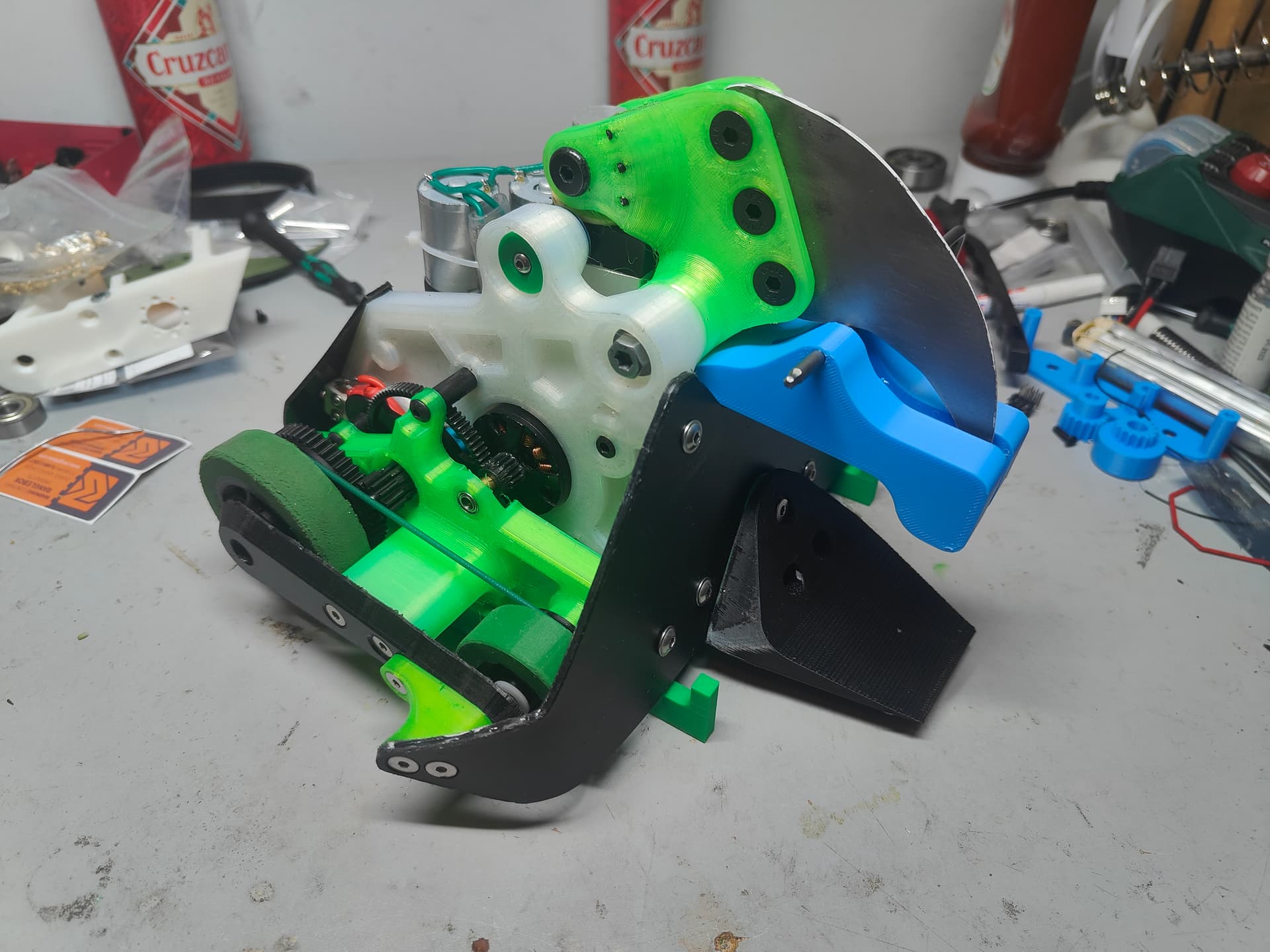
Because I forget about features until the very end of the build I had to do something slightly oddball about my locking bar and sharp edge. I think making them into one is a pretty good way of doing things but Nips is a bit of an ugly duckling to retrofit to in hindsight. I keep kidding myself I’m getting better about it but it’s a very fundamental part of weapon design I always ignore and have to patch in as an afterthought. The blue plastic hooks in under the pivot point and folds to lock the jaw against the frame, then a 5mm pin (or Allen key) holds the whole lot solidly to the robot. To remove you pull the pin and slide the blue part up and out by pulling it upwards and away from the robot.
There is a knack to it that I had got by sitting and doing it multiple times but it’s not super intuitive for anyone getting their hands on it for the first time, like an arena marshal por ejemplo
But it was well and truly finished, for real this time. It had been an exceptionally long journey from December 2023 where I had the idea for Hard Nips stuck overnight in Schiphol Airport in a thunderstorm on a comedown. It has grown into its own weird little thing and I couldn’t be happier with what it turned out like.
Spanning 3 distinct redesigns across two CAD packages it took a lot to actually get this into the arena. I wasn’t married to the shape or the techniques, moreso using it as a vehicle to use a specific set of components in a way I thought was fun. This V3 wasn’t everything it could be, nor was it perfect but it existed. It had to get shoved out into the world or else it was just going to get stuck in a semi vaporous idle grave.
**Champs
**
First and last event of the year for me. It’s been a while since I have ventured out from my cave but it’s always worthwhile for BBB. I’d entered Hard Nips into an event last year but had to pull as it just wasn’t going finished or going to be very good. This time Nipzo was finished but was pretty far from being good.
My first fight was against EMP and Stasis (pictured above) which was a deceptively massive vertical spinner. Honestly there wasn’t an awful lot to tell, couldn’t get to grips with driving fast enough, made a mistake and got clipped in the rear.
The armour/dust cover suffered a critical existence failure when it got hit which launched me up, out and into the OOTA zone. it was torn in half and the wires were snipped which rendered the rest of the bot powerless. The panel was a write off but I could made a replacement on the fly. What was more concerning was going in and patching the wires back on the ESC. Basically the only part in the robot that I couldn’t really stomach replacing (because it wasn’t sub £10 on aliexpress) was a hard target.
@IrregularJoe was a regular gentleman and lent me a rather snazzy soldering iron and I got to work patching the loom back together. It was a slightly laborious process as you can see by my chaotic bench spread what I needed to take apart to get to the one area I needed to work on.
It was patched up with a 3mm HDPE plate bolted in place of the curved back panel with about 5 minutes to spare before it actually fought. I was putting the last couple holes in as I was summoned. Sunstroke is a dual horizontal spinner which I have been really loving from a novelty and appearance perspective.
That’ll teach me to be nice. Never again. Yes flattery falls rather deaf on robot ears and Sunstroke did an awful lot of damage to Nard Hips in an incredibly short amount of time. One knock, again on the rear which was offered up in a dreadful display of control just had disastrous knock on effects which left me dead in the water straight away.
Damage localised arseward and yet again the rear plate was pinged off, which left the wiring exposed. Everything got a nasty yank.
All 4 bulkheads are split through, two beyond patching. Both rear wheels were smashed at the hub, with the tyre material holding the left side together. The front right had been hit but kept intact by the polyurethane. The RH drive bulkhead just split and shattered which just caused it to lose all integrity. Same went for the RH central bulkhead where a combination of direct hits and the inserts being twisted and pulled out as the panels were ripped just gave up and delaminated.
It just was not good enough. It was done. While I did have spare drive bulkheads and wheels I couldn’t quite face the fact of patching it up again just to trundle in circles and continue to not be very good. There was no sensible way to armour up the rear with the central bulkheads smashed and patching the wiring loom again wasn’t on my good time funk n soul playlist.
There the day ended for myself and Hard Nips. Blown away by the standard of robots yet again as it just seems on the up and up. As I mentioned on the events post it is really incredible to see what the UK produces, not just in terms of robots but the events themselves. Huge respect to all concerned for giving us this space to play in.
Thoughts:
Shocked but not surprised is about where I am at with my performance with this robot. I know in my heart of hearts it’s not ever going to do very well just due to the increase in quality and dedication people have for their craft these days but I had higher hopes than I normally do and actually managed to fall shorter than my decidedly low performance average.
It wasn’t strong enough. Pure and simple, and a relatively easy one to sort out going forward. I have access to a lot more resources and machinery now than when I started out on the Nips journey and In the last ~6mo my design discipline is a heck of a lot stronger than it was when I was in the meat of this lad.
The printed nylon construction that has worked well for me for years was woeful. I think this is partially down to it being less forgiving with the part geometry on something like Nips compared to the small dense squares of MotherLoader or Klaus and the fact these were just printed badly. I’m not entirely certain what changed along the way but something certainly wasn’t up to scratch with the layer adhesion. The eSun nylon is generally pretty good at being flexible and impact resistant. These were not. Potentially fighting the weight and dropping the infill down didn’t help either. I think they had a thinner wall than previous parts too. Orientation was potentially something that needed greater attention also.
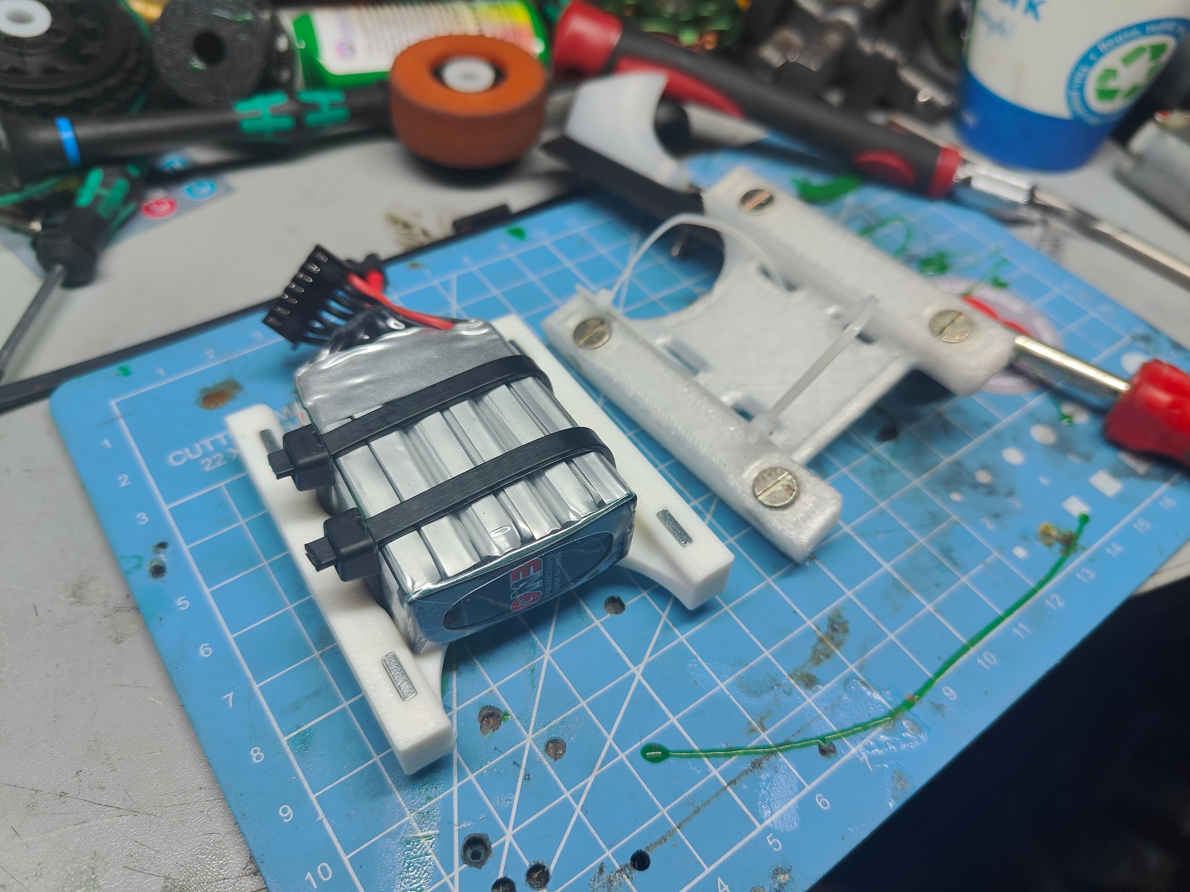
HDPE was just too thin or was mounted to something that wasn’t able to keep it together. As easy as they are, the screw in inserts contributed massively to the structural failure of the panels under impact. Barrel nuts are great but heavy. The captive square nuts in the battery mounting brace worked incredibly well and I want to pursue that further.
Driving and control needs a solid mention as that was pretty poor. Either nerves, focus or a lack of understanding on what to do just created a snowball of bad decisions. It was more of a bitter pill as this was the robot I have had by far and away the most driving practice with. I want to get it a bit more definite I think and stop trying to baby it about. I need to lock the wheelie problem down so I can better deal with trying to make the robot do, well, *something.
*
Maybe too I need to be a bit more active with things and try and just get more arena time or at least some sparing practice so I can breed familiarity with the process of driving a robot in combat. This year will have about 25 seconds of fight time for me - which is probably not helping things. I think it’s probably a wise move to push through a sportsman class or pub league first to just brute force a learning curve.
I felt really out of step coming away from this. It seems I have forgotten how to build robots, or have lost what little grip I had on what modern combat is like. It just felt like everyone was playing chess and I was having a hard time with connect 4. Hard to articulate but it just felt like I’d sort of pushed too far away from the goal and had truly forked off to the side. I try to balance entertaining myself with good end product but I had my finger on the scales and was pushing down hard in one direction. No prizes for guessing which.
I can normally pride myself on the robot being able to tank hits and keep electrically robust throughout most punishment - but this was just not happening here. I think too much wilful ignorance and “it’ll be all right” or “it’s not good but my hands are tied” happened and it plastered over fairly glaring flaws. It feels like another step back in performance which is concerning.
To end on a more positive note. I’m still happy with Nips as a concept for physically existing in spite of all odds. He’s an ugly duck but he’s mine and I love him.
Outside the competition the drive was fantastic. I think operator error killed any potential it has but it sure has legs (wheels) and I will be keeping that style going forward. It might be a weight distribution thing not helping either or traction. Honestly I need to sink those hours in to find out. PLA worked great for the gears but not so much for the cores. Will go back to ABS or go down another avenue entirely
The stance of the machine was great, I loved how it sat and the proportions were pretty lovely. It was probably one of the better looking machines I have made and I’ll be trying to keep that or work towards highlighting its best features in future.
6s was an excellent upgrade, even though it came with some carbon related challenges. It was like the first time I ran a FW spinner on 6s and had a lightbulb moment. I think it is the key for power going forward. The Repeat Dual was a trooper even though it went through the mincer more than any other individual component in any of my beetles. I hope it survived (I can’t check for a little while now) but I will be keeping that going forward.
In terms of my organisation around the machine during the build and refinement process I can say I really nailed down the Minimum Viable Product as from very early days I had it sat at the 85% complete mark. I was able to sign up for a competition with a robot that was pretty much ready to go, submit POM the same day and just focus on tweakage in the interim weeks. This was pretty wasted in hindsight as the avenues I took to improve did not help in the slightest as the core flaws in the jaws were too great to be improved by brackets, widgets and a spare actuator. If I didn’t explode my washing machine, lock both the robot and my tools in a shipping container over a weekend and waste two evenings seeing Tron: Ares (Yes, twice. Once on opening night and then a second time a few days later to make sure I didn’t like it) I may have been able to run a bit more driving practice but again, I don’t think that would have helped me overcome the intrinsic rubbishness.
I think the development going forward will push for a smaller, tougher nips using the same overall style and theme but much, much better construction and engineering thought behind it. I’m fizzing with ideas currently but I’ll let the dust settle a while and keep a few plates spinning as I have a backlog of other robot jobs I desperately need to finish and get out the door.
All that I can say is it can’t get any worse.
Harder, Nippier.