Amazing job on turning around the updated prototype already, it looks fab. The door great drive to both weeks is [chef’s kiss].
Good grief that’s appalling.
Thanks for the advice! I’ll keep all of this in mind when I start printing parts myself.
Well all my stuff did get chucked back over the ocean to America’s Best Bud, China. Practically speaking it’s probably gone into landfill but I’ll get my 17 pounds back one way or the other.
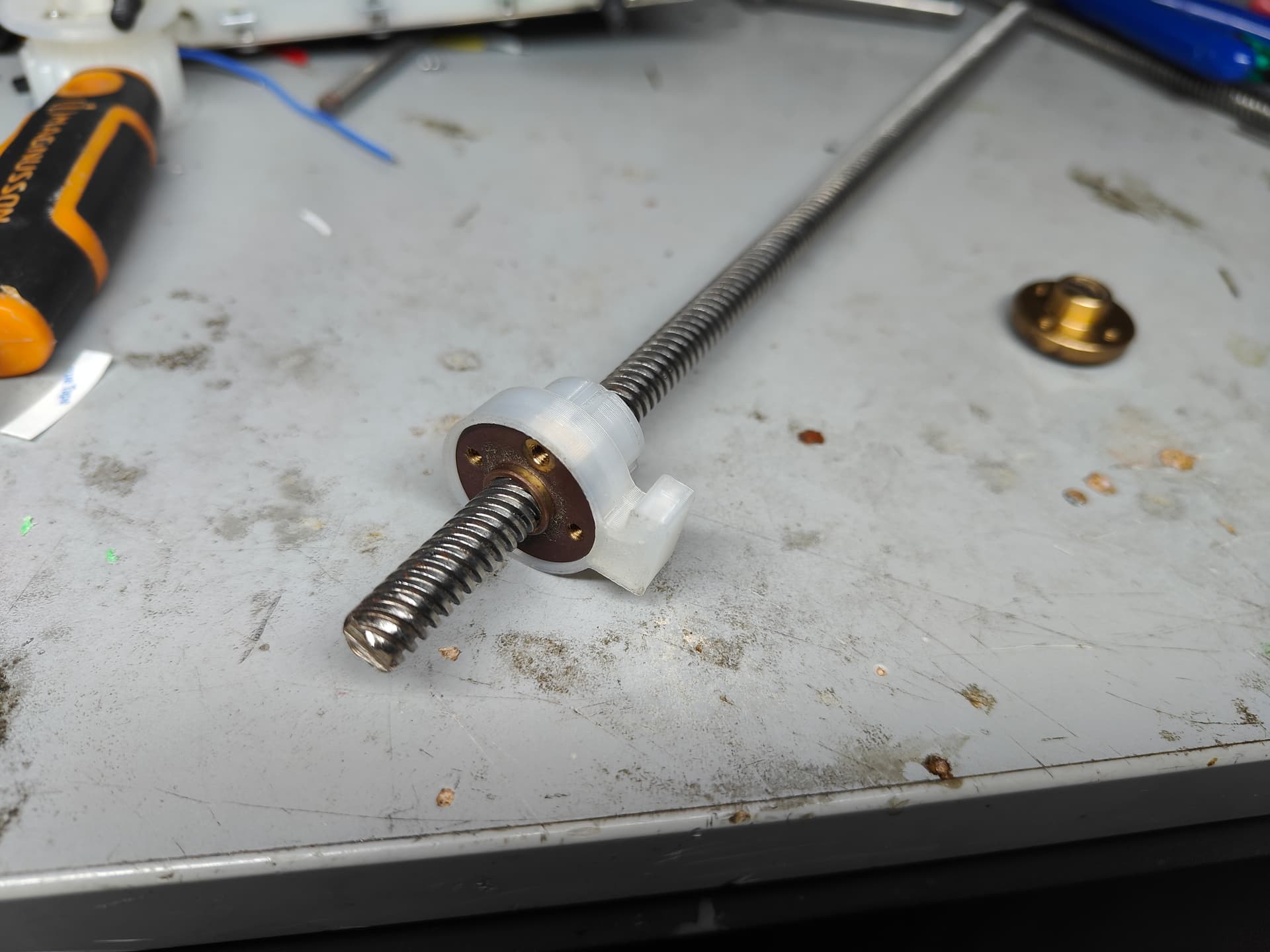
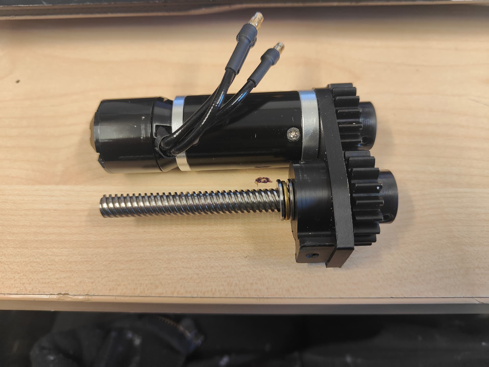
Mad respect to the King of Kings, @IrregularJoe who stepped in to offer me some of his personal junk/precious artifacts. I liberated two leadscrews and a neat PCB as a trinket from that absolute legend. Wouldn’t you know it, it fits perfectly with the nylon adapter I had preemptively spunked out based on AliExpress dims.
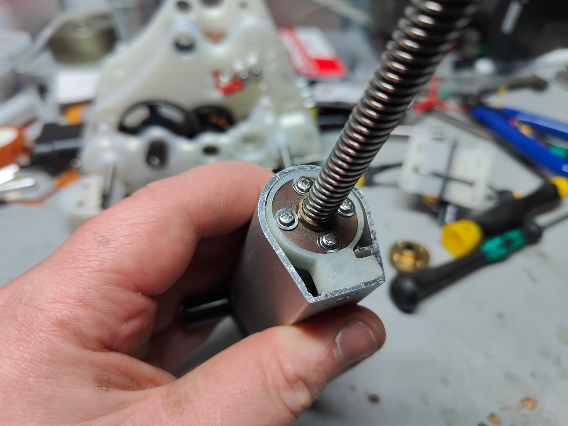
Retrofitting into the actuator tube like so! These nuts are actually tapped for M3 so I might get clever and pop flip and reverse it so I can use them. Currently it’s shady self tappers into the nylon. Doesn’t really matter as they see no shear except on retract where load is minimal.
I still need to figure out my thrust loading bit now I have slightly more stuff in hand it’s going to be relatively trivial.
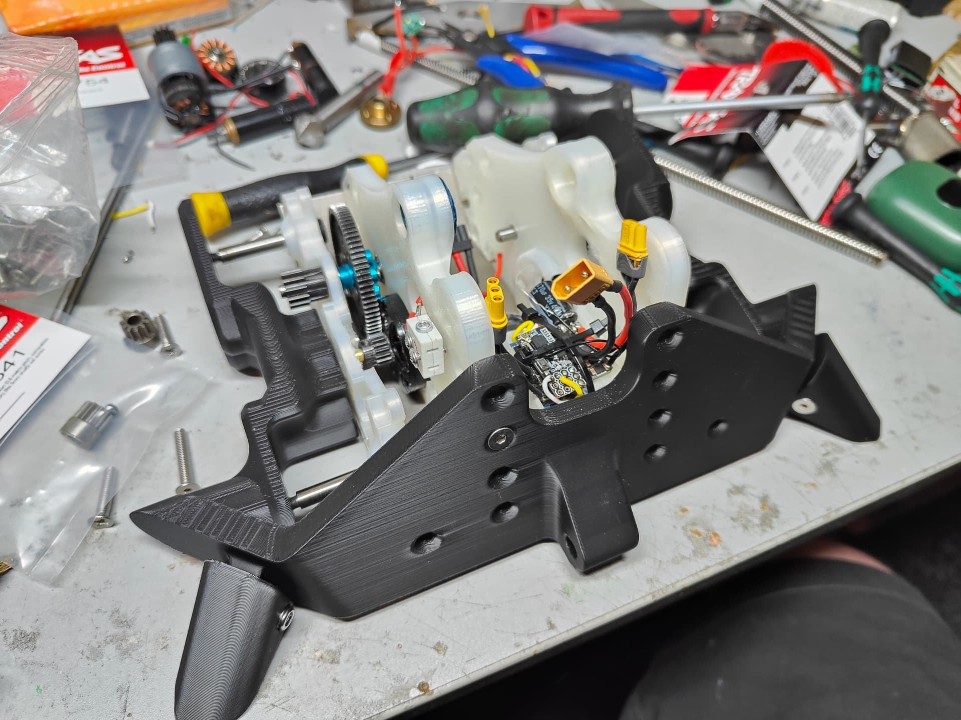
I have stepped up to complicate my life yet again with a bit of gyro stabilised naughtiness! I cleaned up the Repeat Dual that had been through the meat grinder at champs and made myself a new stack of electrical tumours. It’s taller than before but sort of better from a pure space management perspective. It’s going to be cradled by a little nylon widget that clips yo the bullheads and has a dual purpose of keeping the battery on the inside.
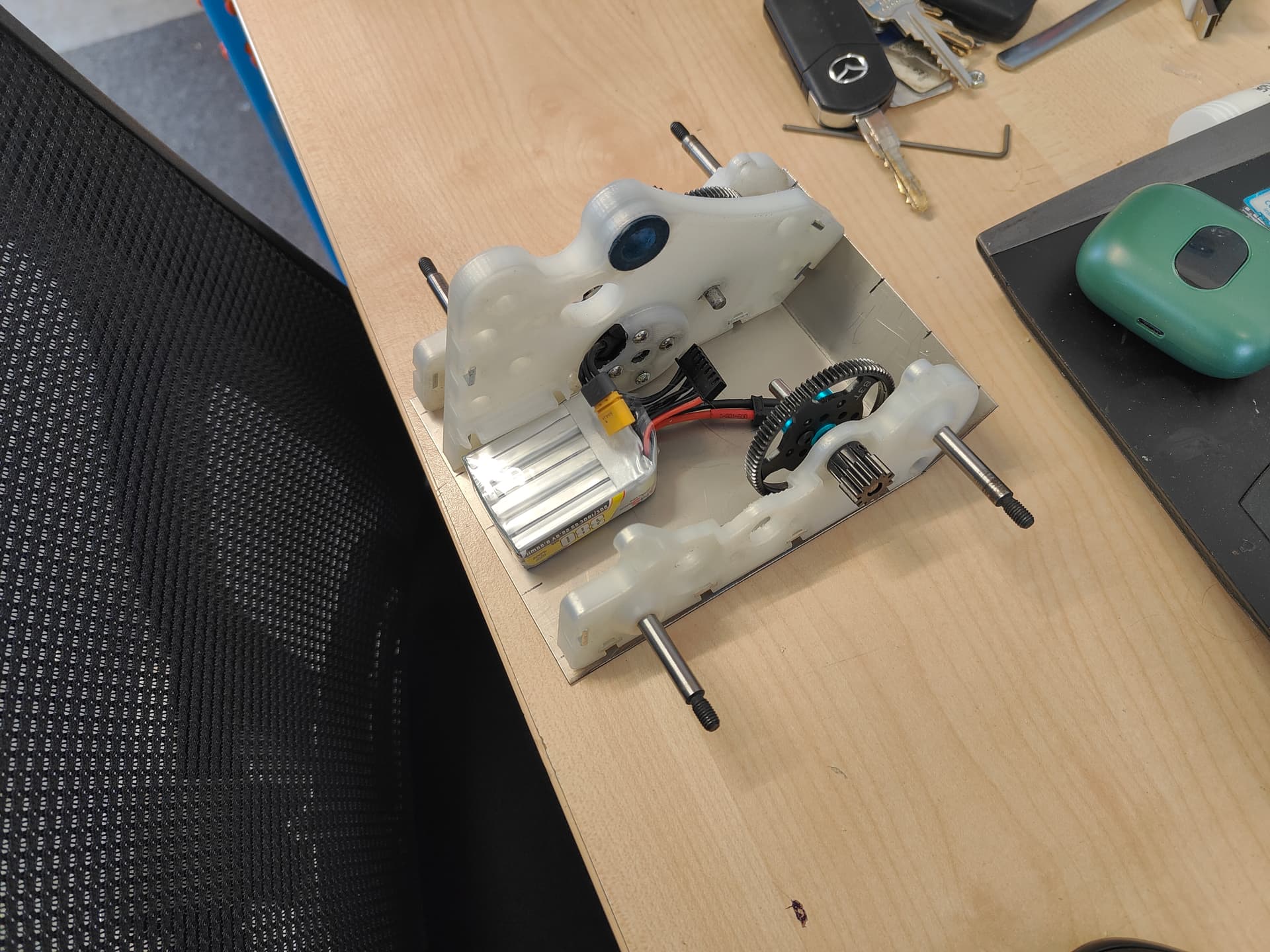
I cut and folded some titanium to make a baseplate. I just used the bullheads to check the bend angle because I’m a filthy hack fraud. #bespoke.
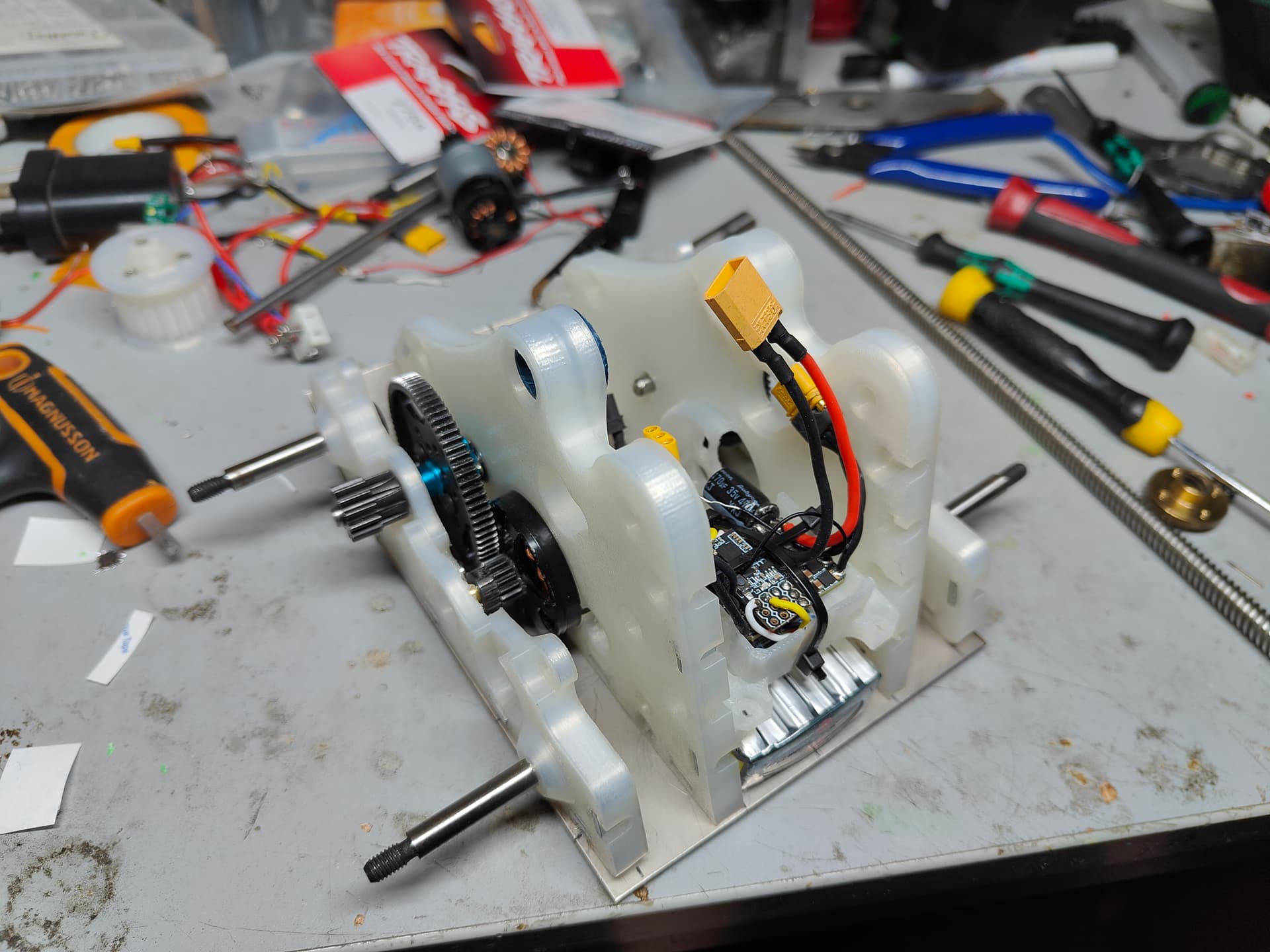
Better idea of the component stacking going on up the front again. The rear of the robot is almost exclusively for actuator swinging and impact absorption.
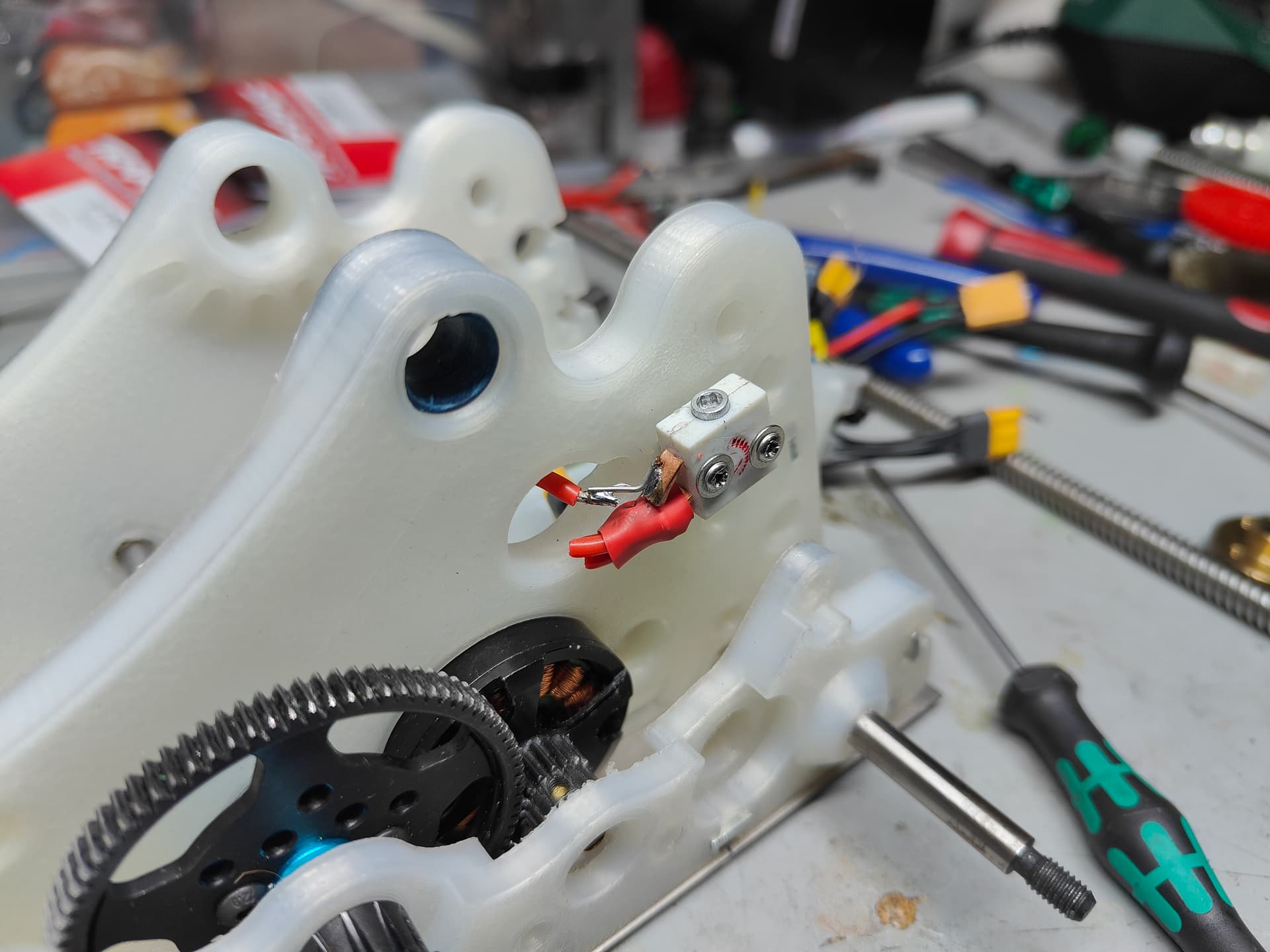
The switch mounts up front, moving with the ESC block. It’ll have a little shroud around it but it’ll mostly be covered by the TPU armour anyway. Please ignore the very stripped heads on the screws, how embarrassing.
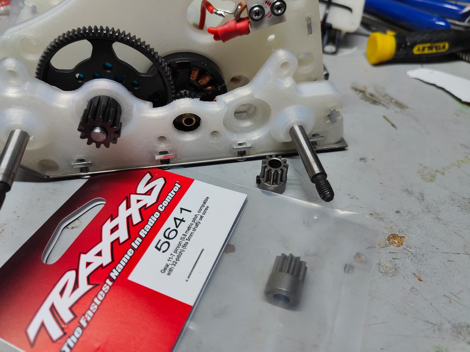
I designed myself into a corner because I am exceptionally incompetent at DFM and good engineering practice. Thank God I don’t do this for a living or something. Basically in order to make the ratio’s work for the drive speeds I had to drop to 0.8 Mod for the fronts and I needed an 11t pinion.
Which was trivial.
With a 5mm bore.
Which was virtually impossible.
Yes I genuinely couldn’t find anything that wasn’t 1/8” because nobody is stupid enough to put a 1:8 scale motor (5mm shaft) into a 1:10 scale RC car and then over gear it. Except Traxxas fanboys! The worst company in RC finally comes good for me!
Couple of packages (from the UK at UK prices!) to go and I can be having a little test drive. We shall see.
4 Likes
It’s not hoarding if you offer it out to folks in need, right? Gotta keep the show on the road.
I will say though… I did my work experience at the UK Traxxas distributor when I was 15 (the postcode on the back of my bag of parts was just down the road, so I sent them a letter and they said “the size of the balls on this kid” and agreed), and when I left on the Friday they sent me home with a Revo 2.5, so I’m in the unfortunate position of having to be just little bit of a fan.
1 Like
Absolutely worth it, though I’m a tamiya/kyosho man at heart. Clicky clunky chunky plastic instead of cheap (fun) speed. Funny how I never carried that attitude into robots… ahem
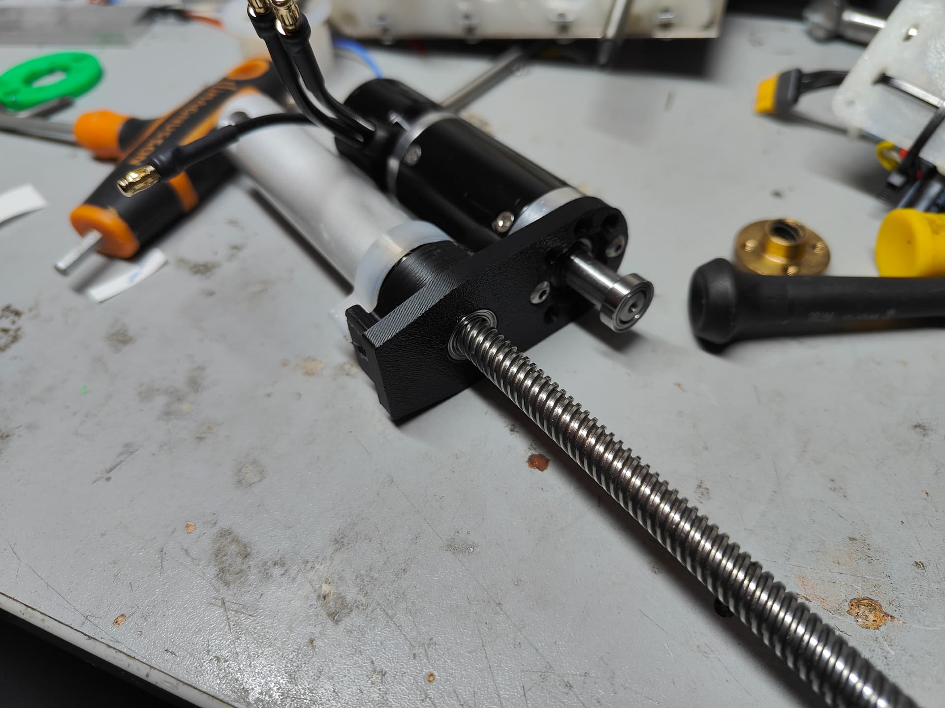
Actuator time! Work continued with the arrival of some MOD1.5 gears and thrust bearings. I’m pretty badly constrained by the total length of the unit, so was struggling to work out my thrust loading (important in an actuator!) without getting too custom or making it too grotesquely long.
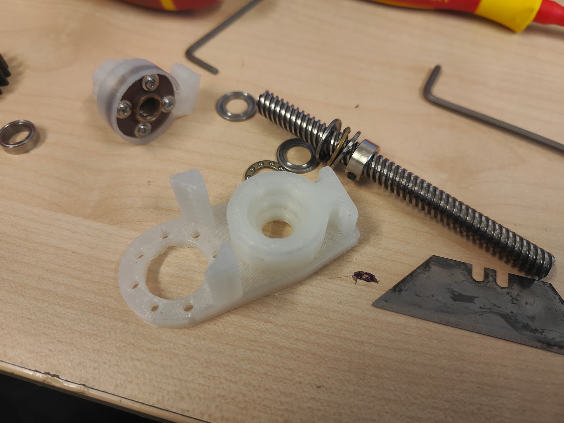
Simplicity won out in the end and I just did the most natural thing of just buying a shaft collar. Naturally with my extreme talent for the straightforward I had to try and spec the thinnest profile collar possible which took me away from industrial and easy (but 7-12mm thick) to modeling standard ones which were thinner at 5mm but nearly £2 each, minimum pack of 5.
Now every millimeter I add of “height” along the leadscrew assembly cuts the already stunted travel of the actuator piston by… well, a millimeter. But by the time I stacked up the thrust bearing and the shaft collar I had cleft my overall travel in twain. Ouch.
Luckily I still had meat in the actuator body so I could shuffle the bores up and down. By reducing the distance between the two bearings in the mount I could add in a pocket and recess the thrust bearing into the main meat of the mount. Bringing them closer together means they lost a good chunk of the rigidity and it’s a black mark against good engineering practices but that’s how I roll. The other thrust bearing is sitting in the pocketed out section of the gear. Bonus design choice from using RC car pinions is they are normally neatly dished out for weight.
I rewiggled it all together and have only “lost” 4.5mm out of the maximum travel instead of 20something so I’m chalking that up as an extreme win deserving of a zesty beverage.
Once I figure out the ESC question (likely a shiny new Vortex if I am a very good boy and eat all my drugs and say no to vegetables) I can start crushing and pinching and get a handle on what Nipz 2.0 is going to be capable of.
4 Likes
Spent a bit of time dutifully reinventing the wheel.
Combination of materials was set, polyethylene tyre, TPU hub, nylon gear but how to make them play nicely together needed a bit of rejigging. The original plan was simple, just requiring an insert into the TPU hub itself but the softness of the material was an irritant property in this regard. I flirted briefly with the idea of standoffs and plates which would have been the peak solution from a strength perspective. However I was running out of space on the 40mm front wheel and couldn’t really do much with it because of the constraints I had already locked myself in with.
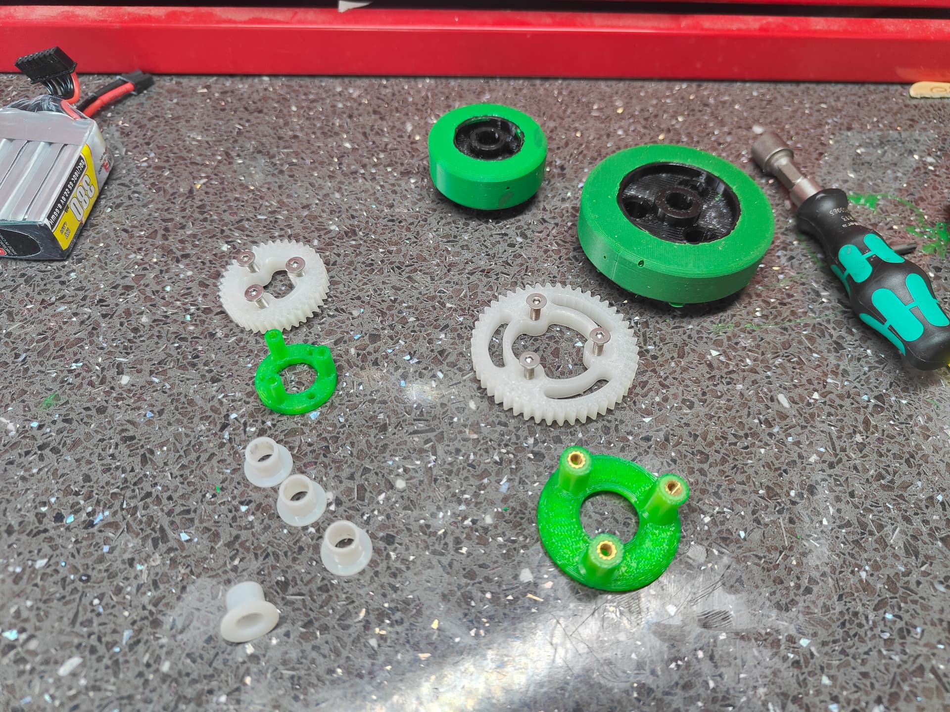
This is the next best thing. More nylon! Yes I had made those little pizza box stands (apparently they’re actually for holding the next slice steady whilst you take yours!?) which pass through the TPU hub and are screwed to the gear.
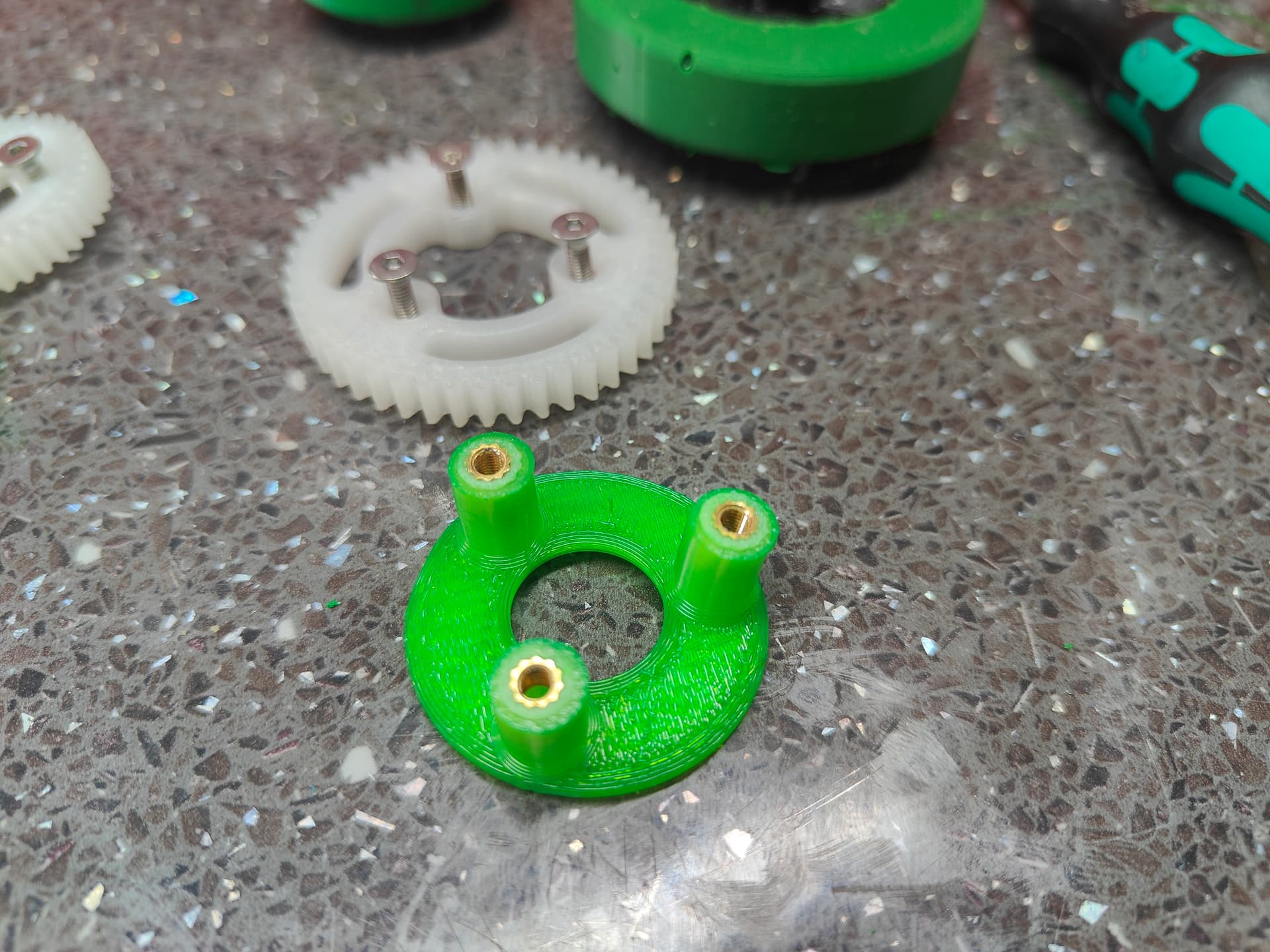
I’m never going to be able to entirely remove myself from heat set inserts - they’re just too handy! In a very technical sense they clamp the hub too but most of the positive engagement is though the pegs and the “inter-clearance” fit of TPU bores. It clicks happily into place with mild thumb pressure, much like how I wish my spinal discs would in my bitter old age.
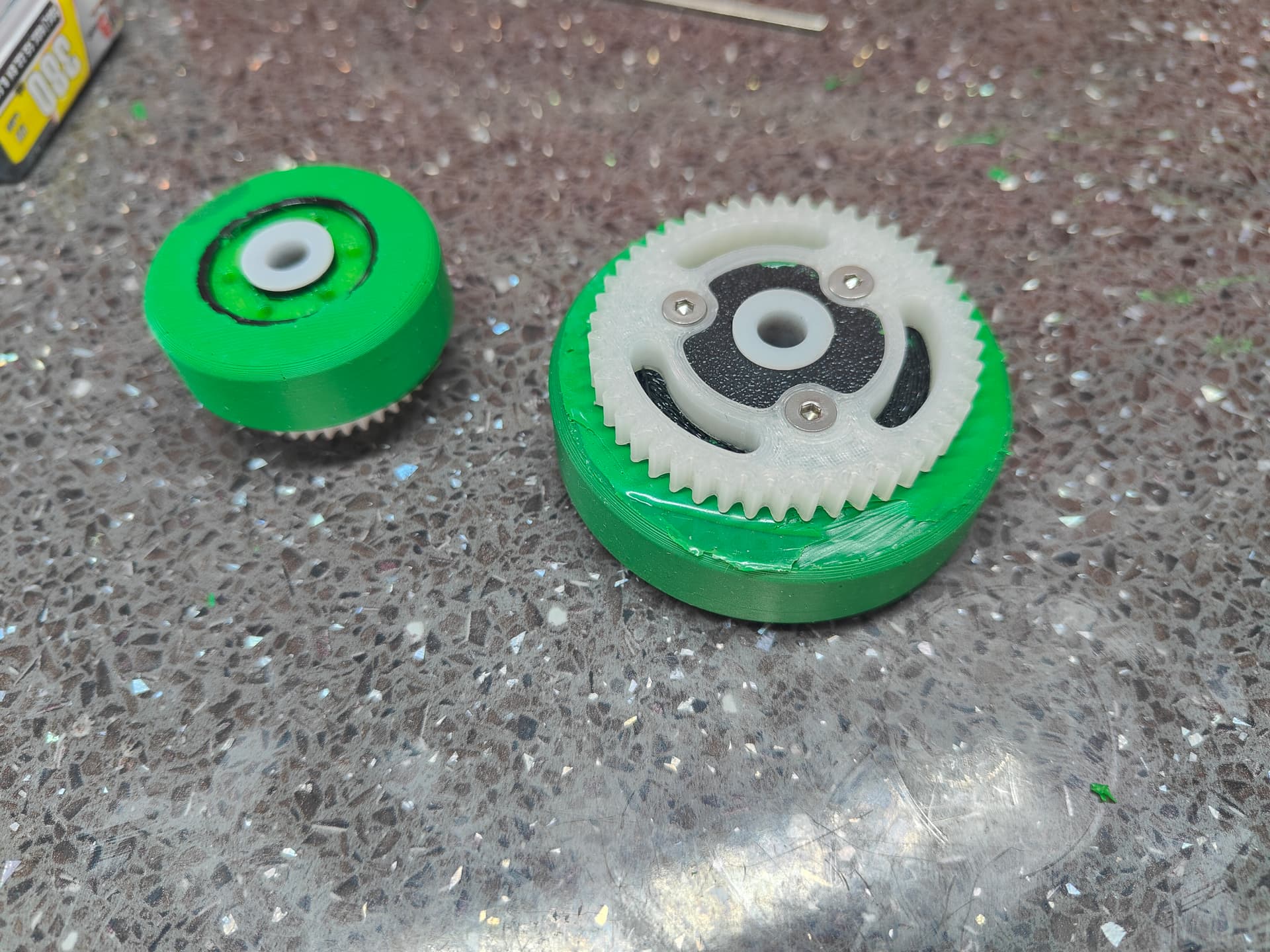
A trio of M3’s hold the lot together. The 60mm rears and the 40mm fronts are pretty similar in that respect. I didn’t dye the gears because they’ve potentially more of a consumable and I like to leave my “working” parts plain where possible.
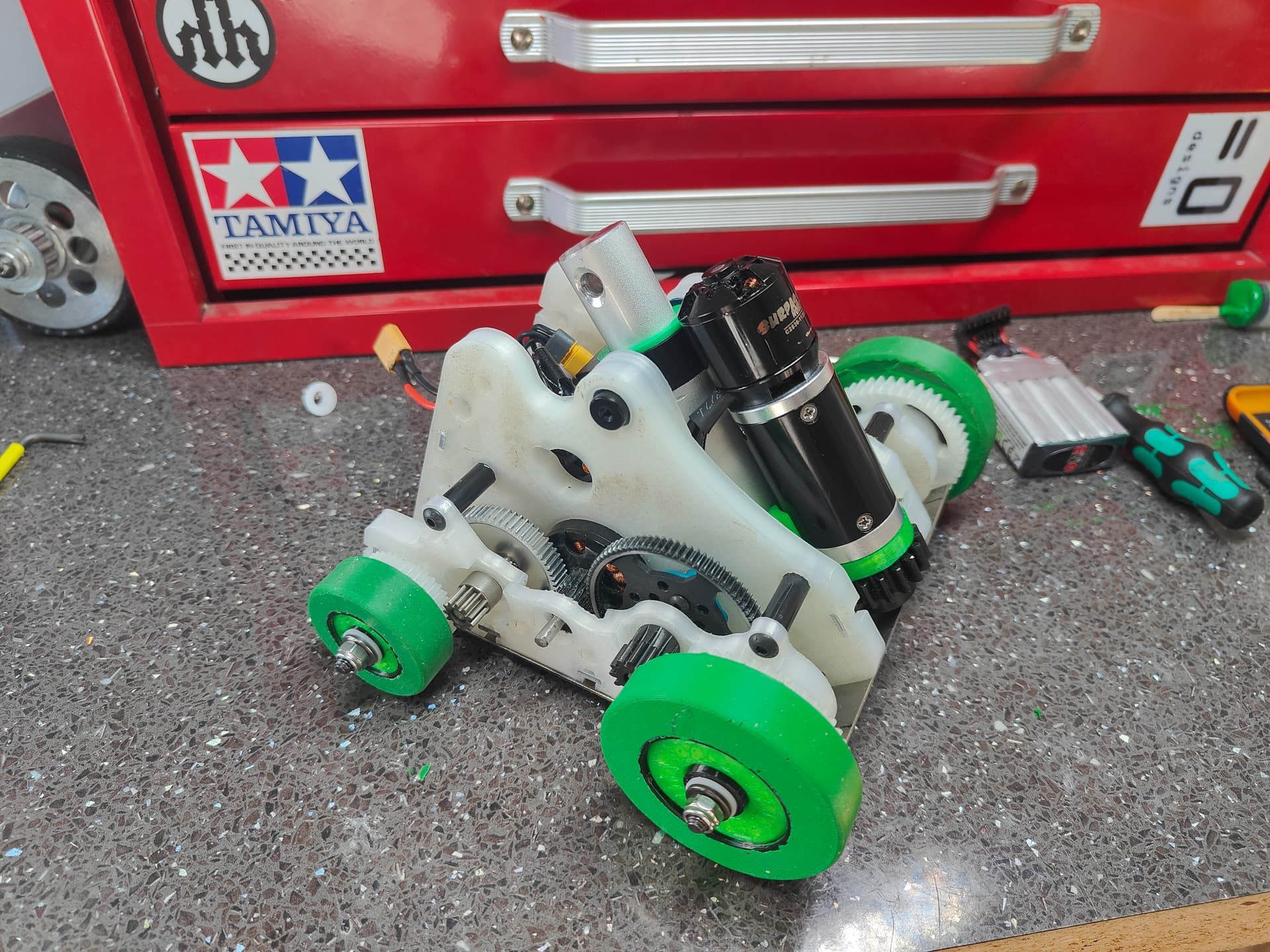
Booties in place I can now start checking reality to see how my maths with the drivetrain has translated.
I feel it’s looking quite smart now, everything is reaching the densely packed stage for sure. Rough estimates give me 108g for a jaw and whatever bum armour I deem fit. I can see it being a very dished our titanium plate jaw with printed knuckle joint and pivots - though hardox isn’t off the table just yet!
Progress carries on. I am just on the cusp of having to start cutting weight - but I have achieved so much more with this version than the last.
3 Likes
Distraction happening here. I have hit a small brick wall with Nipso where I waiting to get a small chunk of steel lasercut and the bolts to arrive. Current estimates put weight at 22g over which is genuinely quite a trivial amount to find in relative nipsonomics.
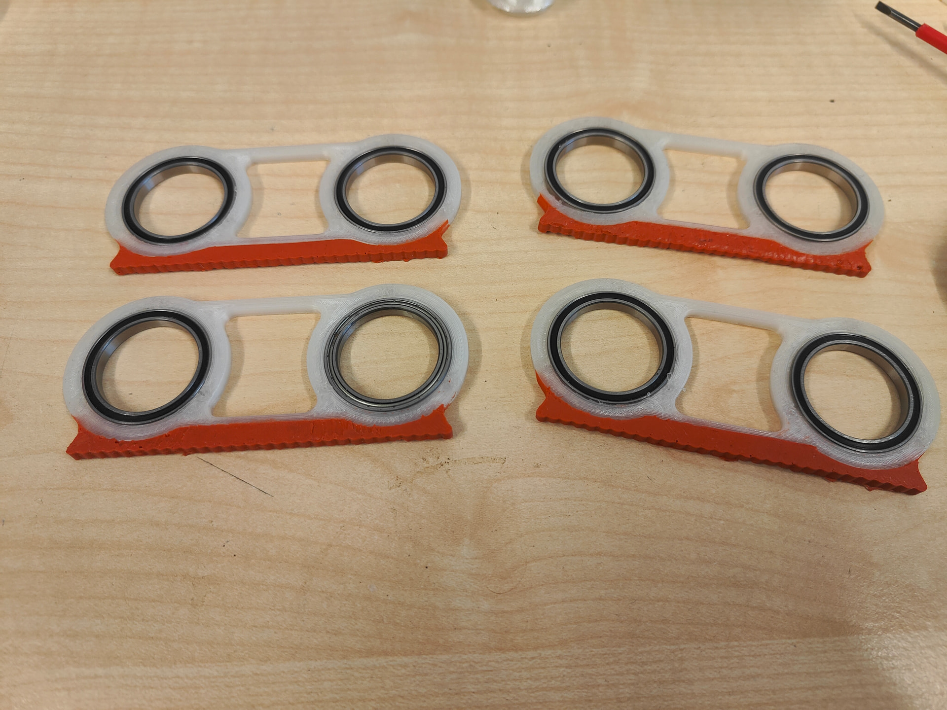
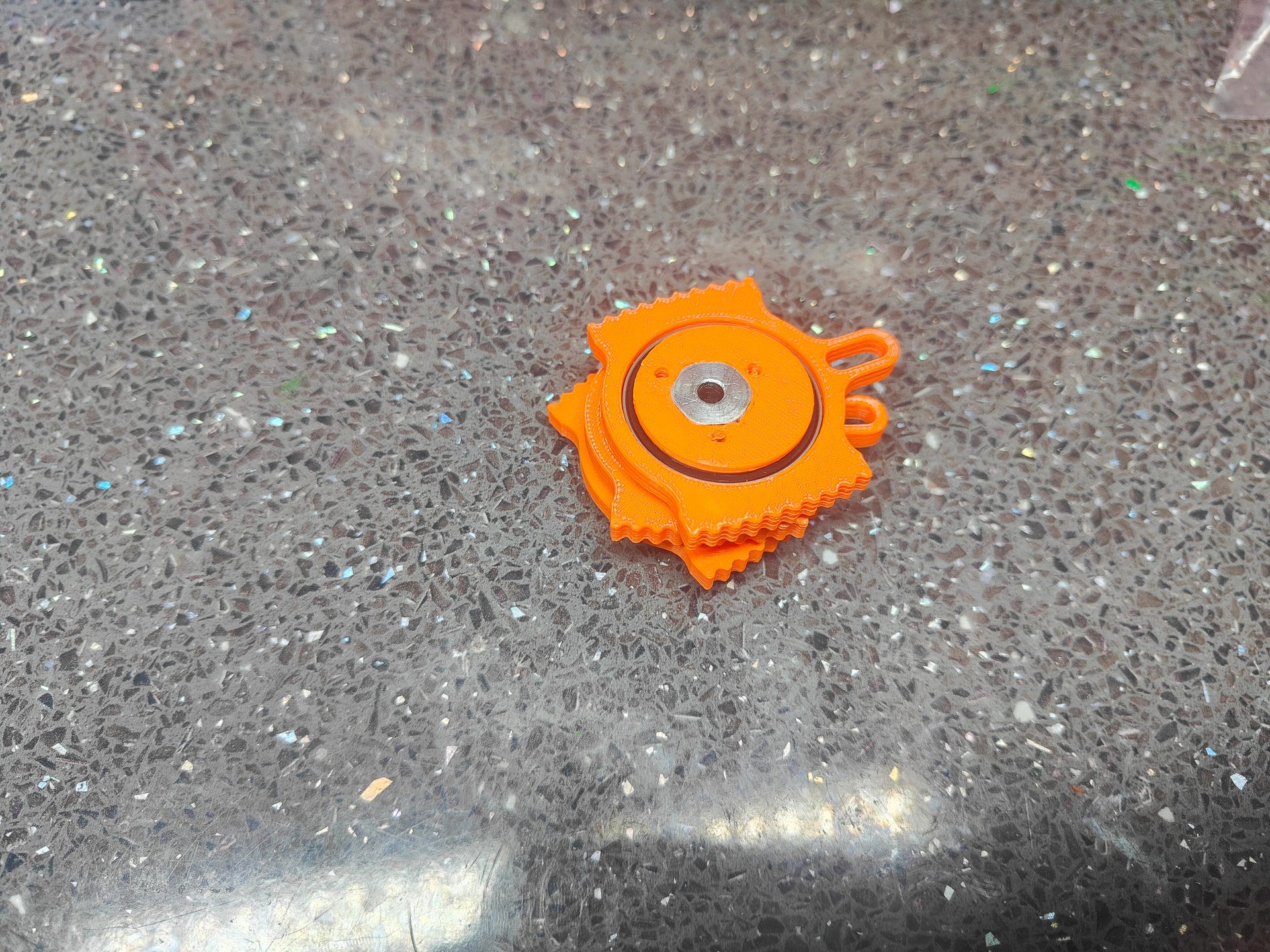
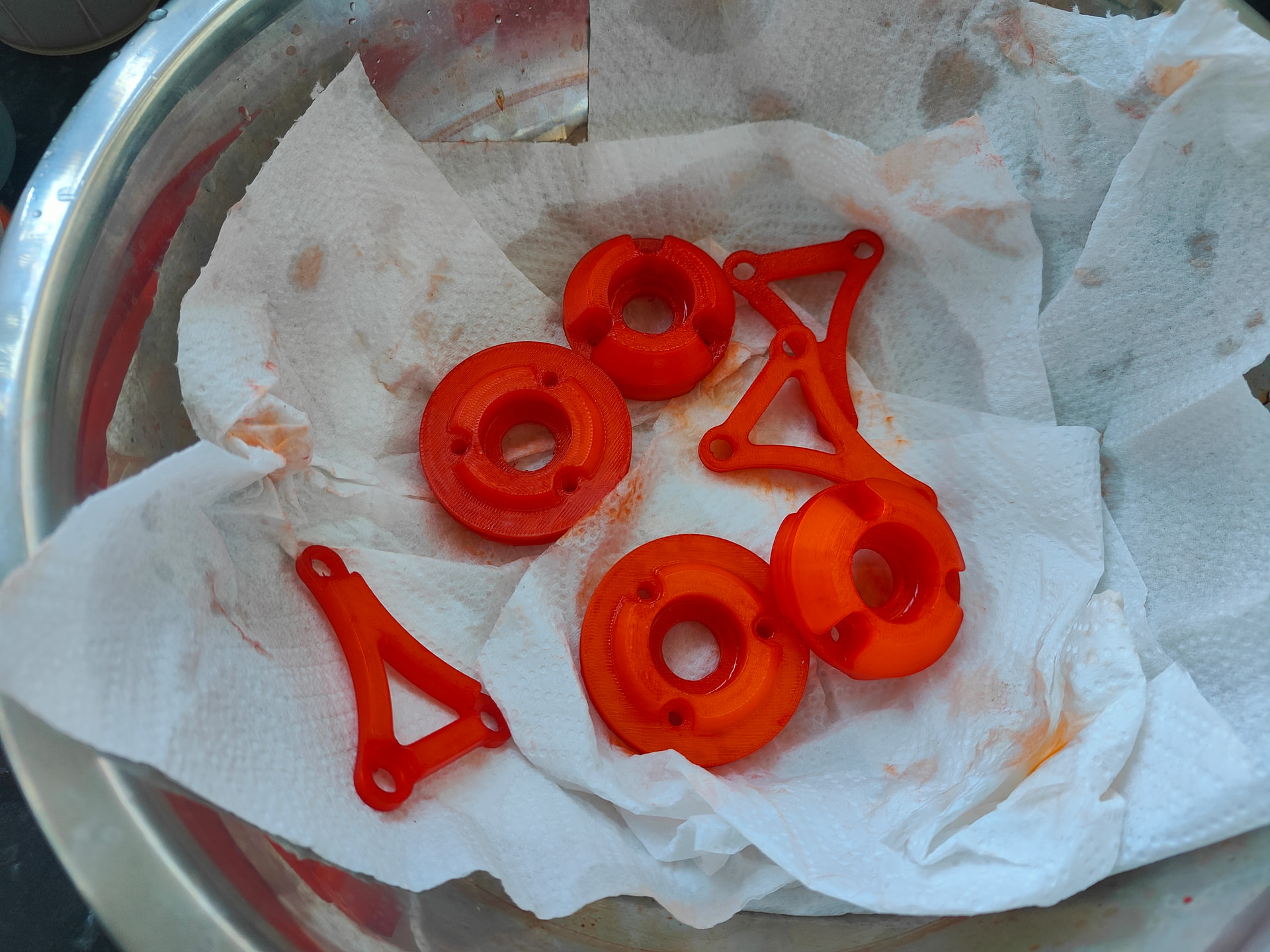
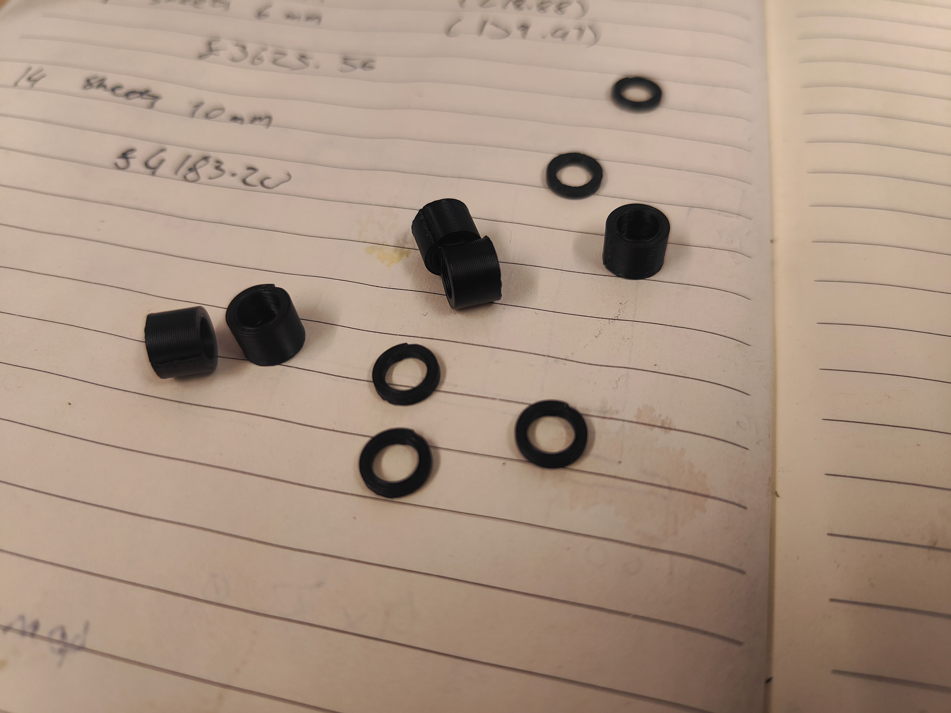
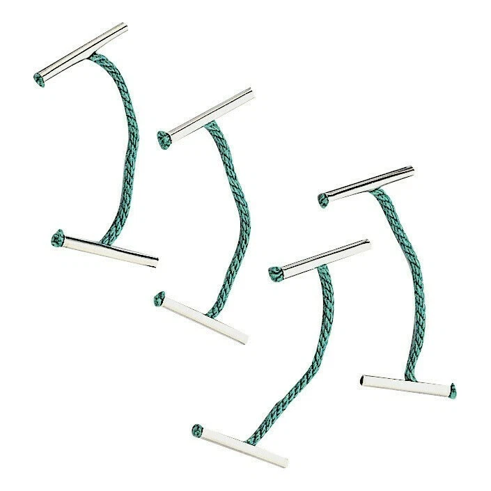
Instead have a little teaser of a bunch of ginger moustaches. Fairly obvious what they are but there’s a lot of convoluted scrimping and hand waving going on behind the curtain…
And yes, it’s infuriating that I was one rubber sealed bearing short. Believe me it hurts me more than you.
3 Likes
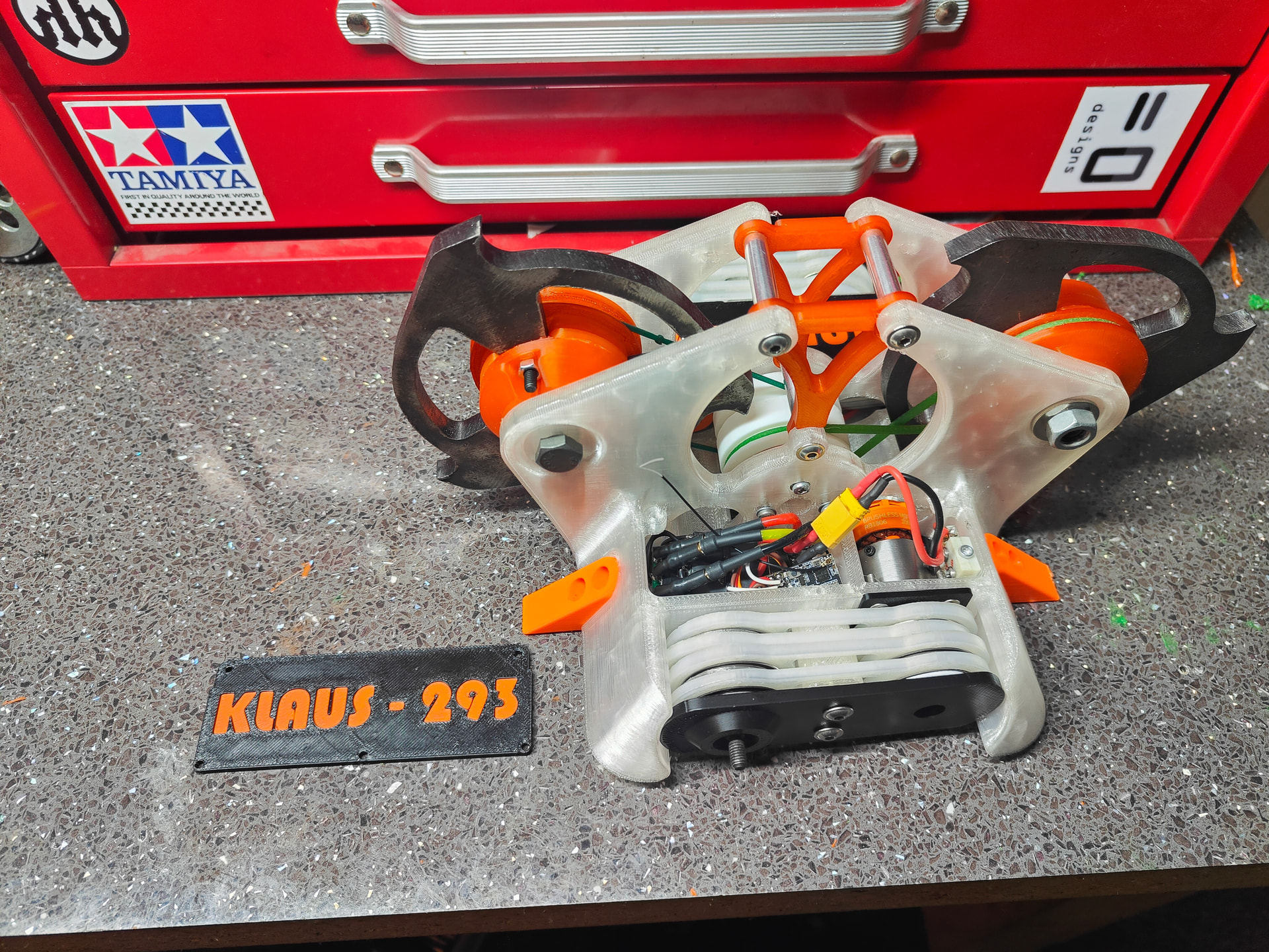
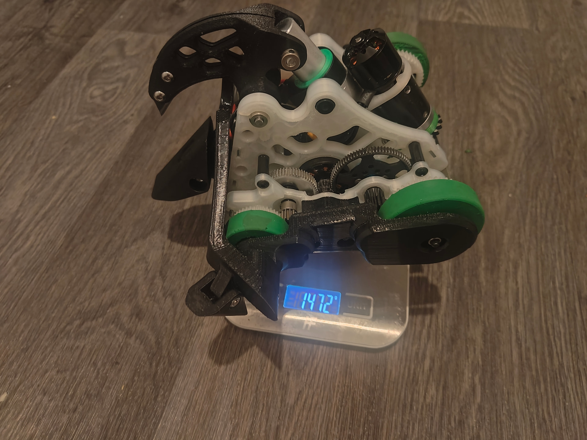
Right. Passing on from the sneaky teaser I have completed a robot to the point I’m happy to talk about it.
Everyone, you remember Klaus?
Well it’s been so long I wouldn’t begrudge you if you had. It was a 4wd “hammer” “saw” with both of those words being used very generously. Ultimately it was one of more successful endeavors. Don’t get me wrong it still lost all its fights but it was a huge bucket of techniques I still use to this day.
It then got rejigged as an overhead saw with tracks. Initially the thoughts were for a newer MotherLoader but the potential for violence and the weapon style put it firmly into Klaus territory. It got close to being completed but never really clicked together to be a fully cohesive project for me. I’m surprised interested in revisiting this as I have done a lot of the legwork and have the parts.
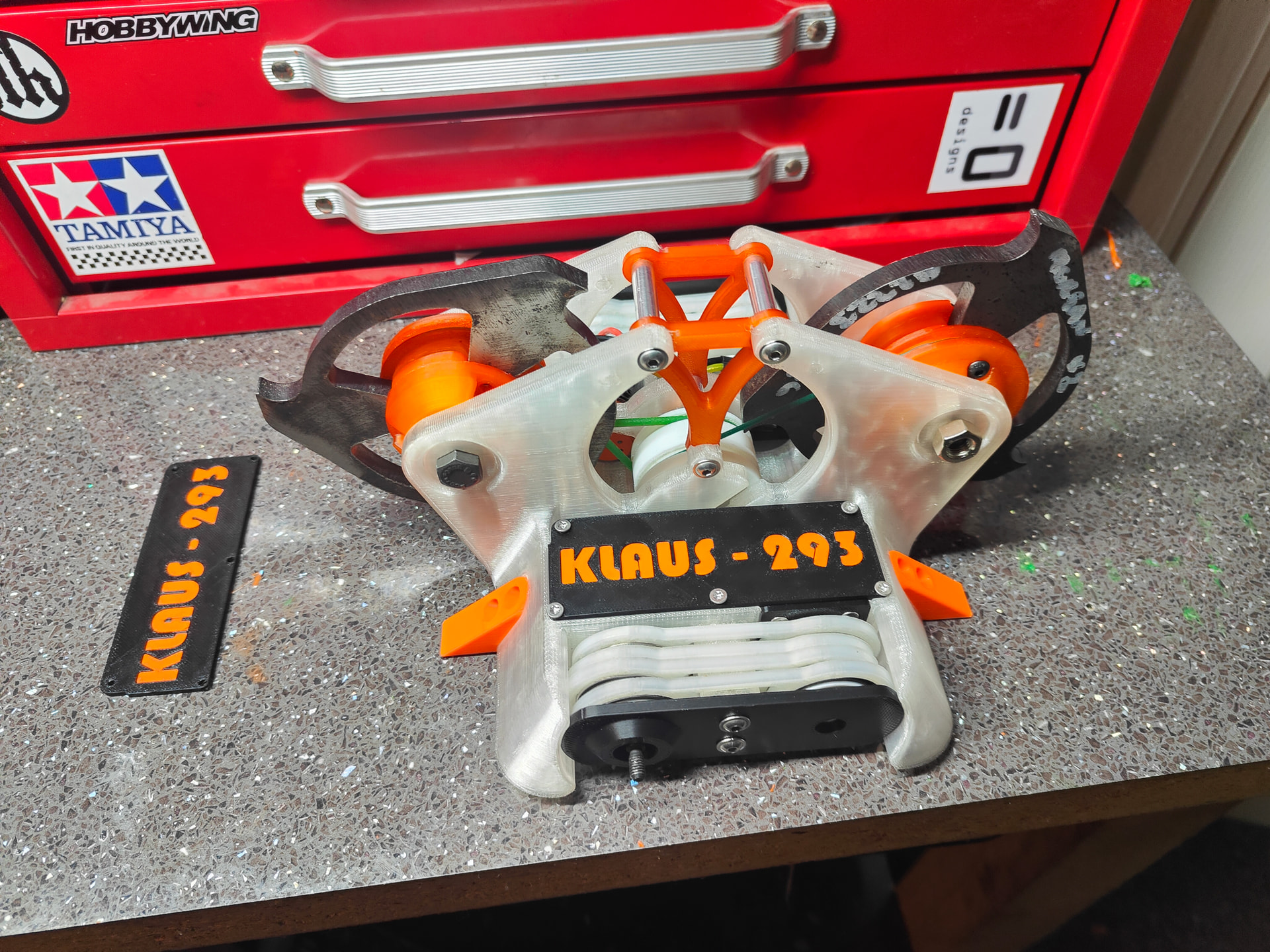
Very recently I was cleaning out some boxes and found some old discs I had cut for a jolly - years back when I did such things - and the brain juices really started flowing and before I knew it I had built:
KLAUS-293
Now I am not a huge fan of the spinner game anymore. I try to not come across holier than thou about it because I genuinely don’t think it’s wrong to build what you want. That’s kinda my whole deal. I make a few limp wristed snippy comments at the BattleBots level events and competitors where things morph unhindered into 4wd verts like an even more unsettling form of carcinisation.
Anyway, I made two verts. As I’ve enjoyed phrasing so far “does this mean I’m trying twice as hard or only tryharding half as much?” Awnsers on a double sided postcard.
Now I started not a million miles away from where I ended up. I wanted to transplant existing parts into this robot and ideally not buy anything as that’s a revolving door of menace for me. My initial inspiration was dual spinners inline and up front like the old American robot “Village Idiot” but I couldn’t really get the idea to stick with me right now.
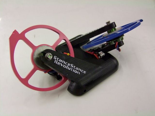
I’m a very simple man with very clear sets of inspirations - Stance Stance Revolution is one (which itself comes from Counter Revolution. My word, it’s like poetry - it rhymes!) I was also tentatively inspired by Sunstroke, a dual disc horizontal that blew the backside out of Dear Mr Nips a couple months back.
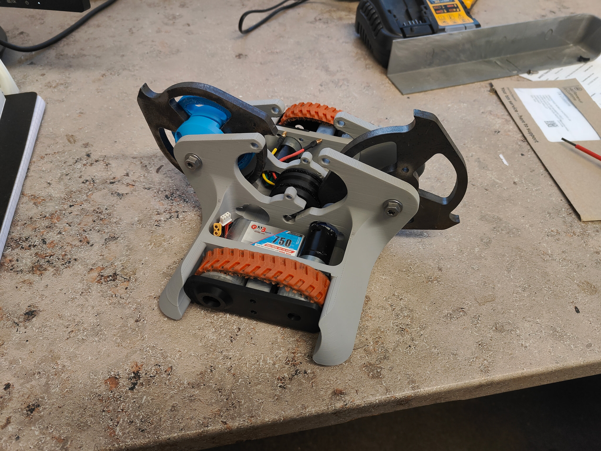
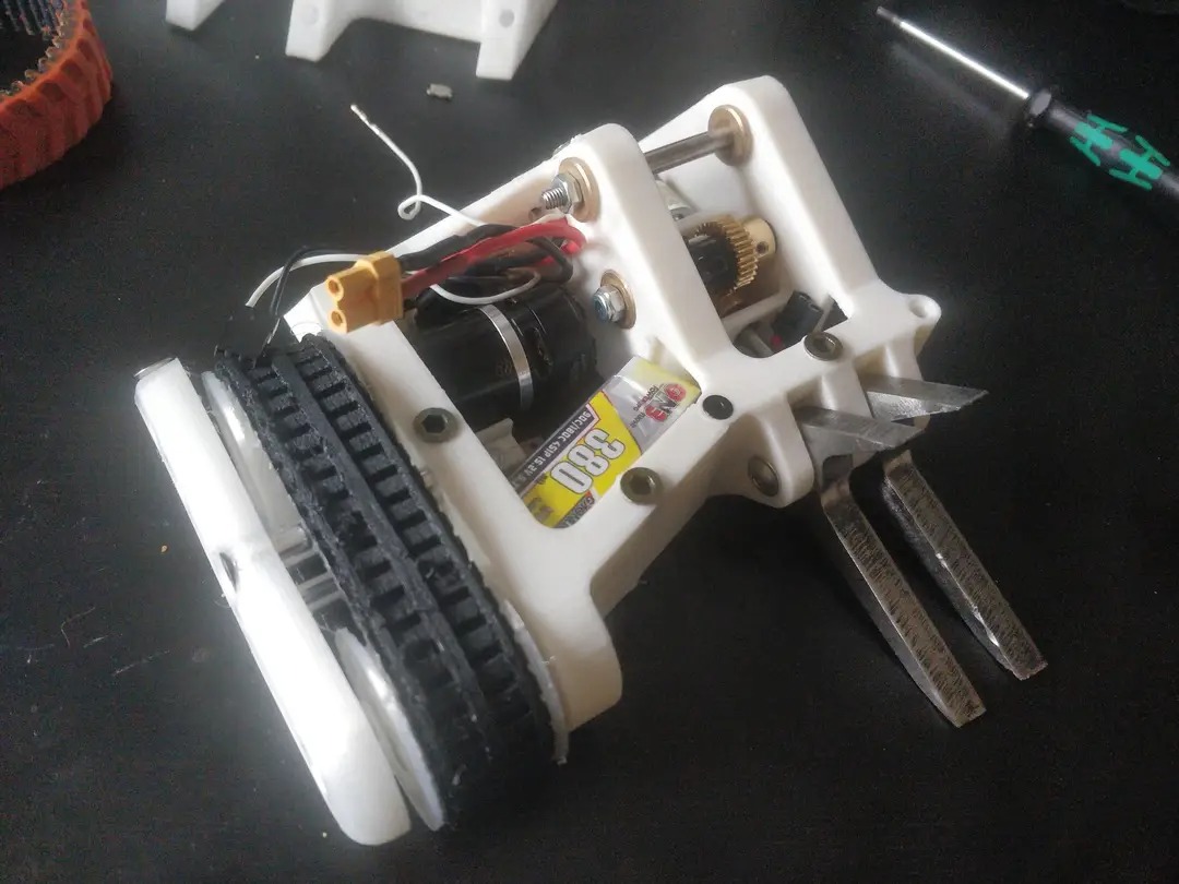
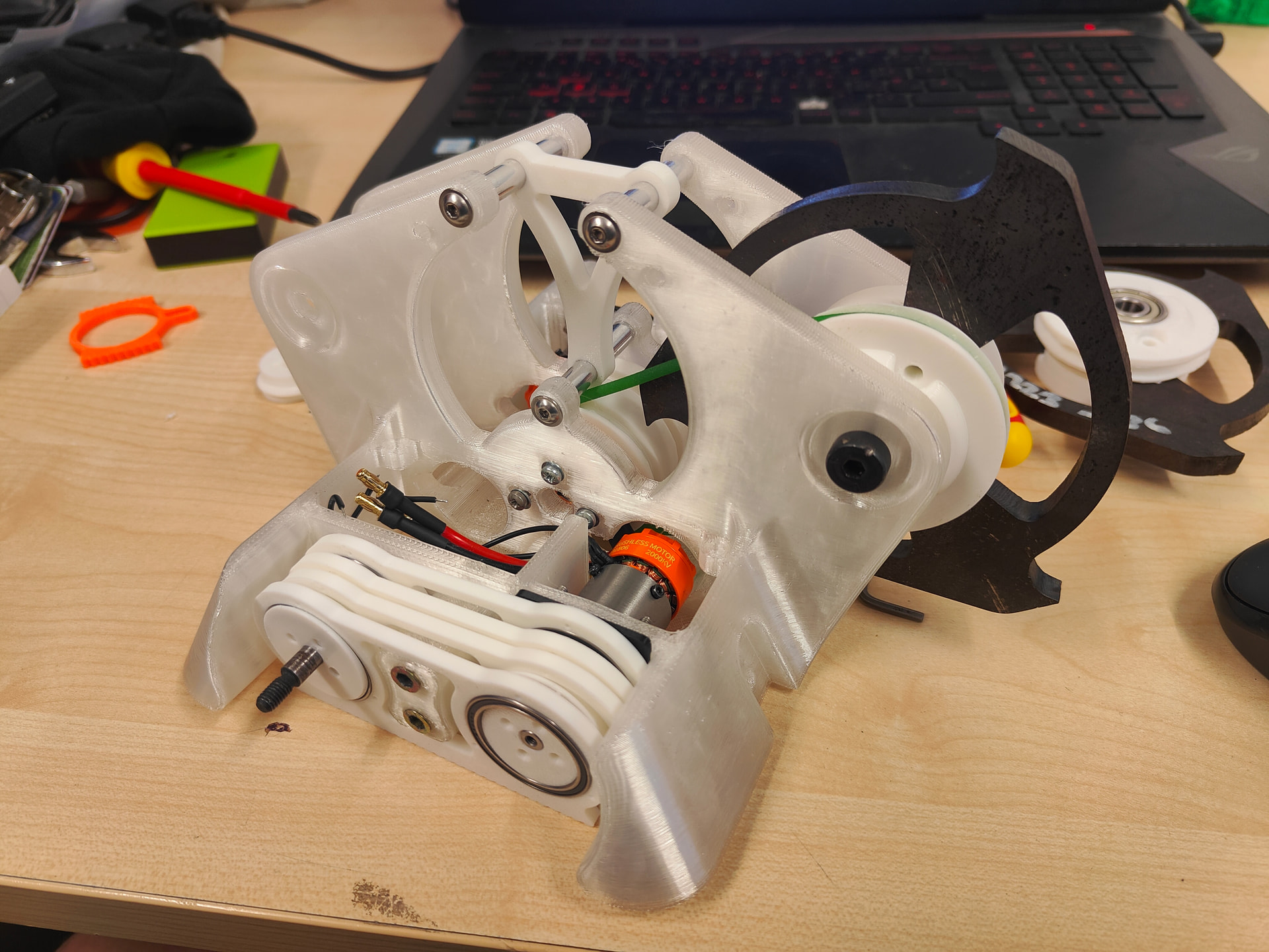
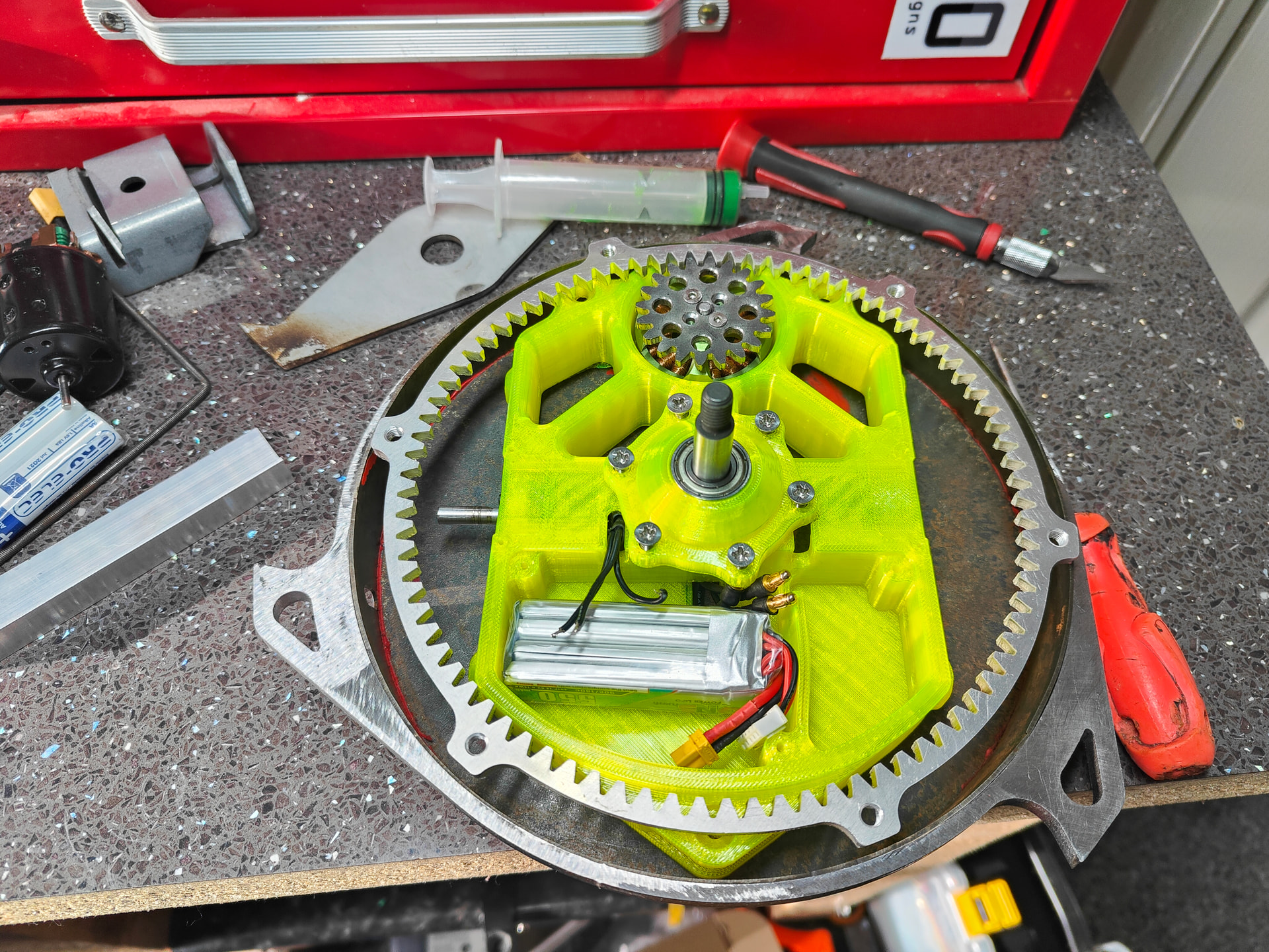
Here was the first serious draft. The drive and proposed electronic system was transplanted from MotherLoader with the bluecap 25mm’s and a BBB dual esc. The tracks were from the overhead saw version of Klaus and the central motor was a 3538(?) NTM which was a veritable monster but was 1800kv. It was heavy, powerful and fast. Honestly before I got too bogged down in weight (spoiler alert) the speed was the killer as I was so limited on how small I could make the drive pulley.
To get the tip speed under the limits the driven pulley on the disc had to be enormous. Heavy and massive target!
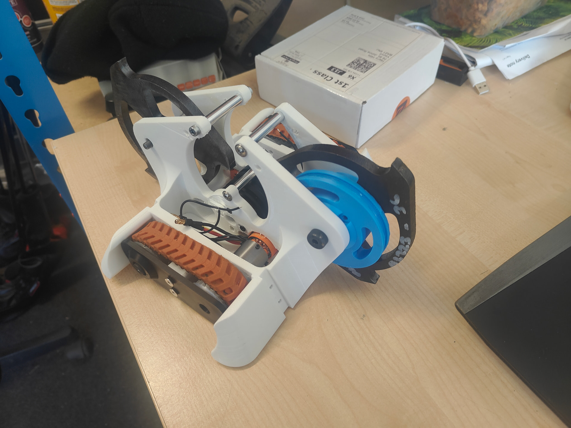
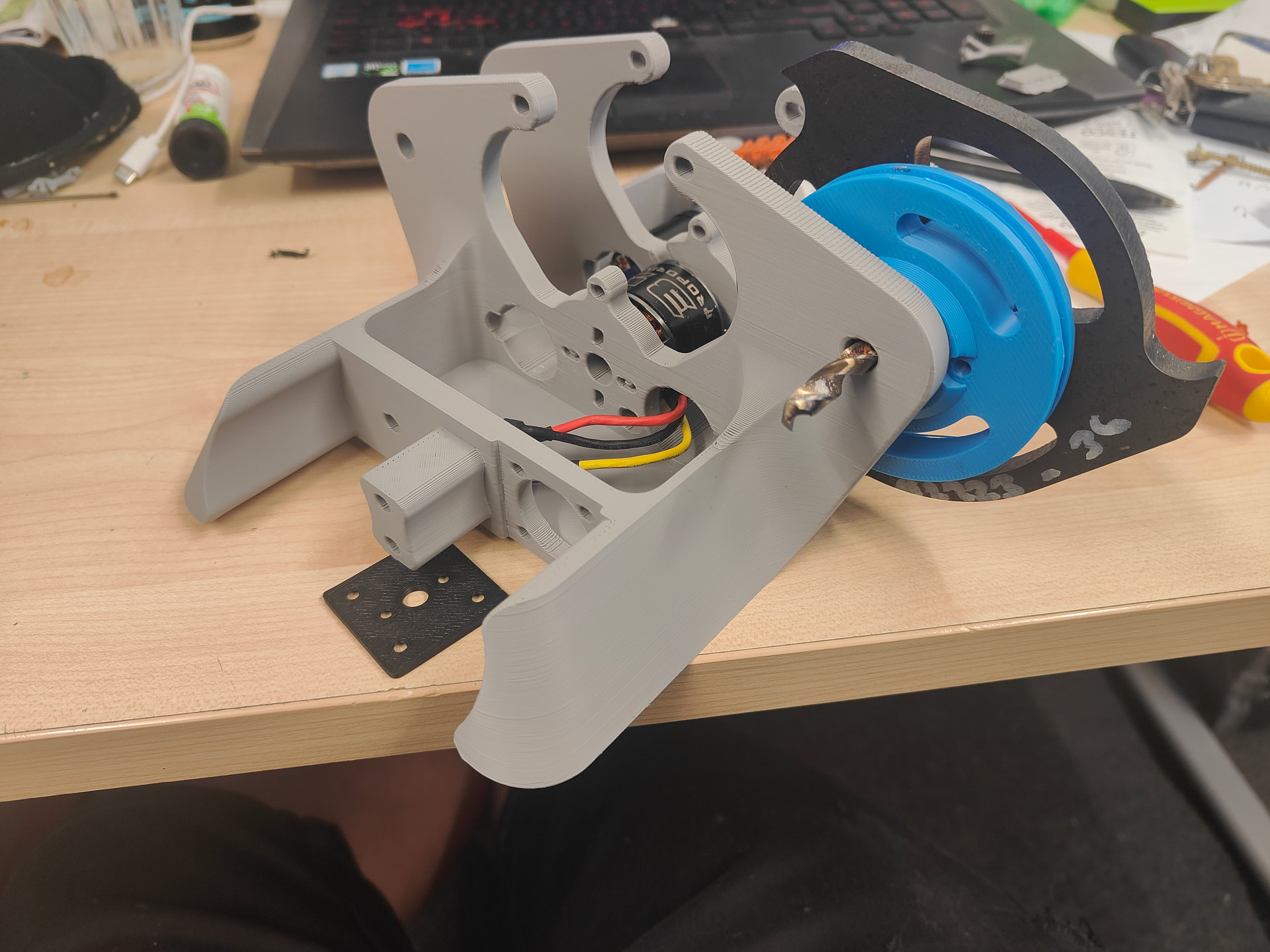
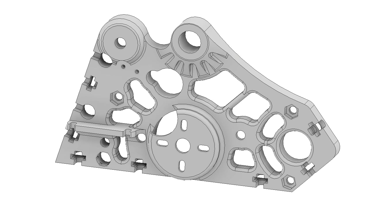
I got to the point where I had made a bunch of revisions with the chassis. My new style of design is an initial sketch where I then derive every part from. It makes sweeping changes very easy and its a practice I need to keep going for sure. This lad is the first TPU frame I printed and you’ll notice the drive got a distinct upgrade too.
Width is weight and I was on a campaign to get this monstrosity as small as possible. The ranglebox MARS are an amazing off the shelf solution. I bought a pair on launch but never had anything that would benefit until right now!
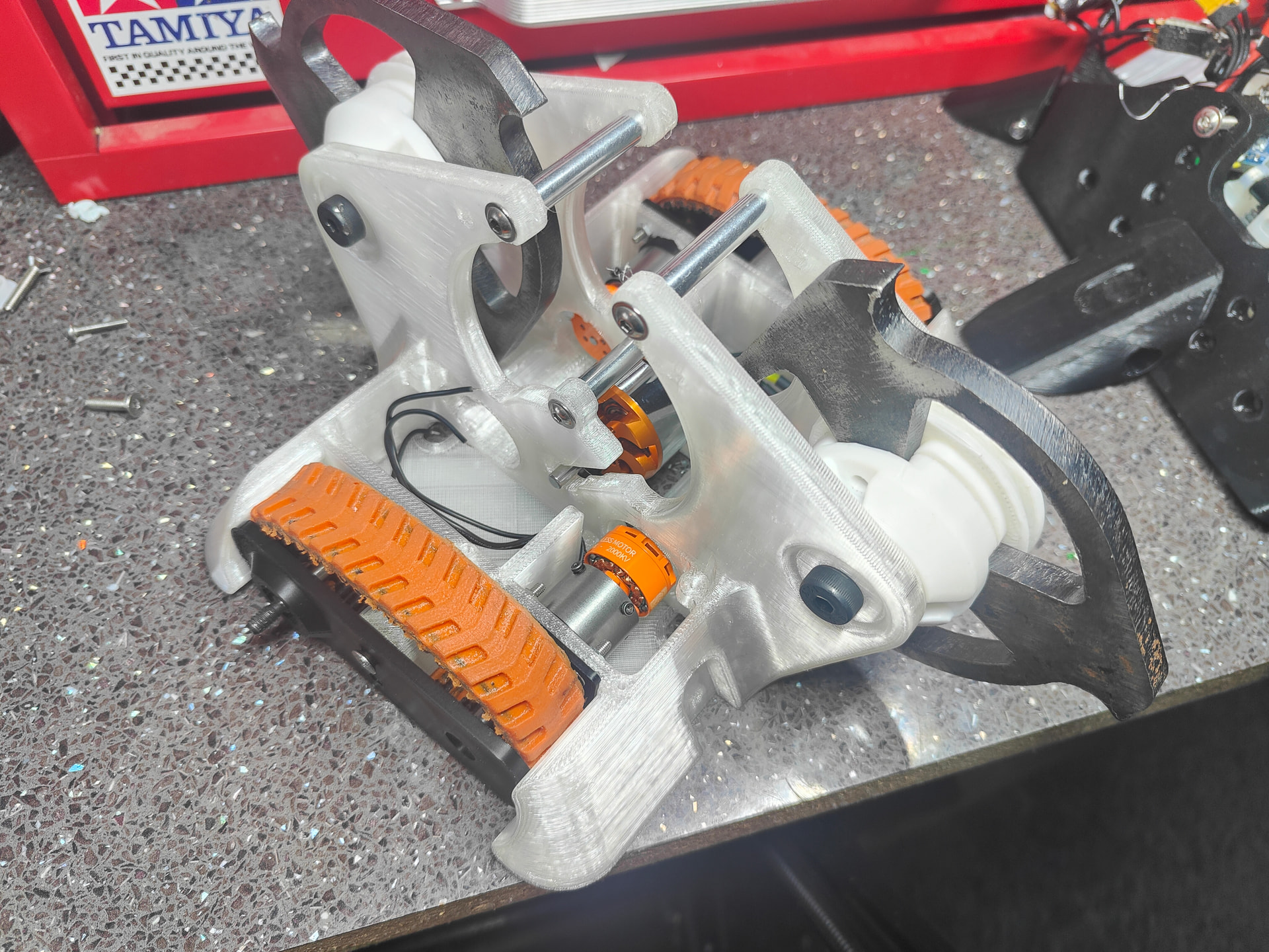
I also reneged on my “don’t buy anything” ethos and spend a whooping £12 on a 3530. This was a smaller, weaker and slower motor but that actually benefited me. I could power it properly from a beetle sized pack, I didn’t have to panic too much about ESC’s and the lower KV meant I could shrink the driven pulley down to much less of a weakness.
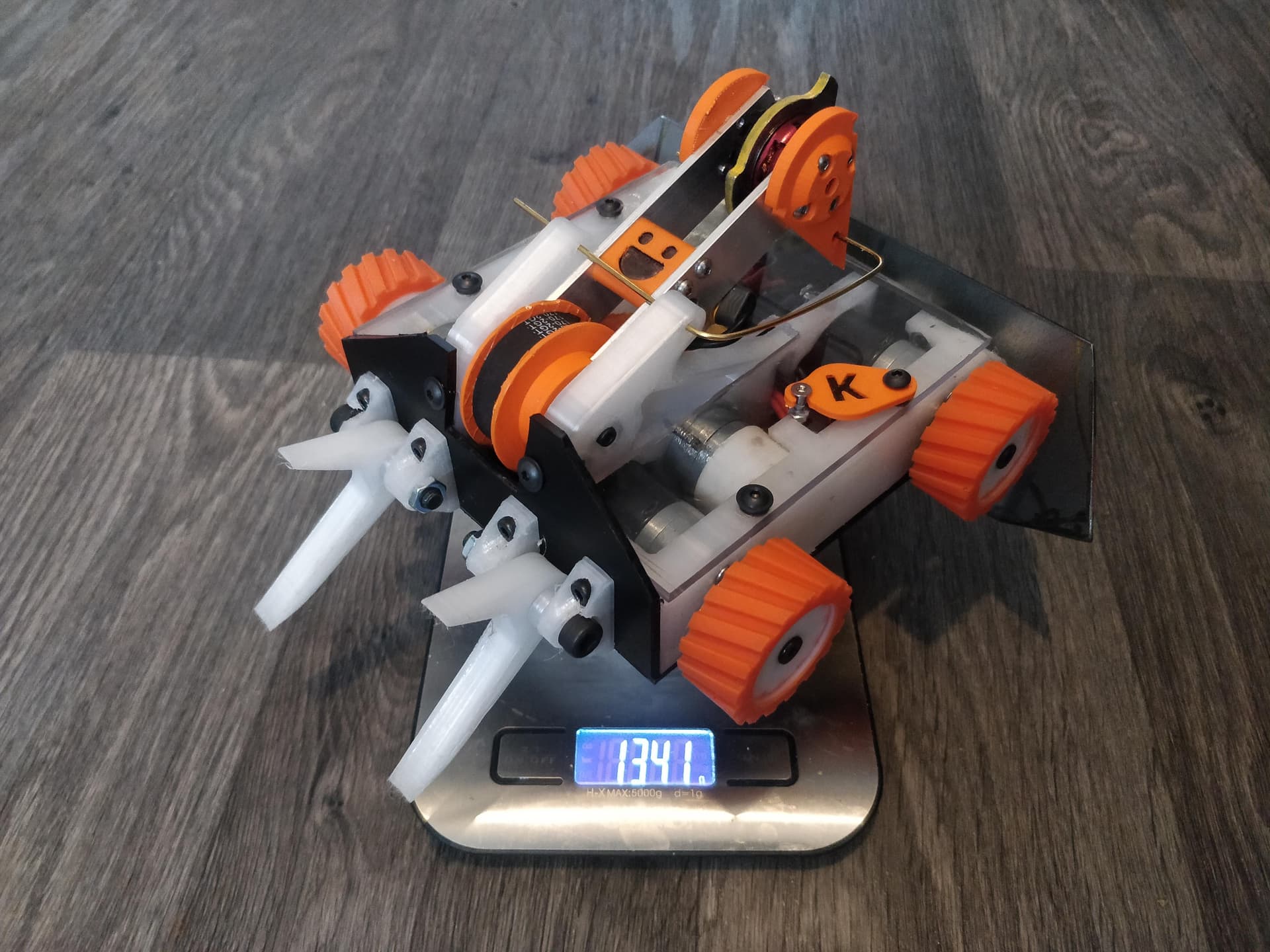
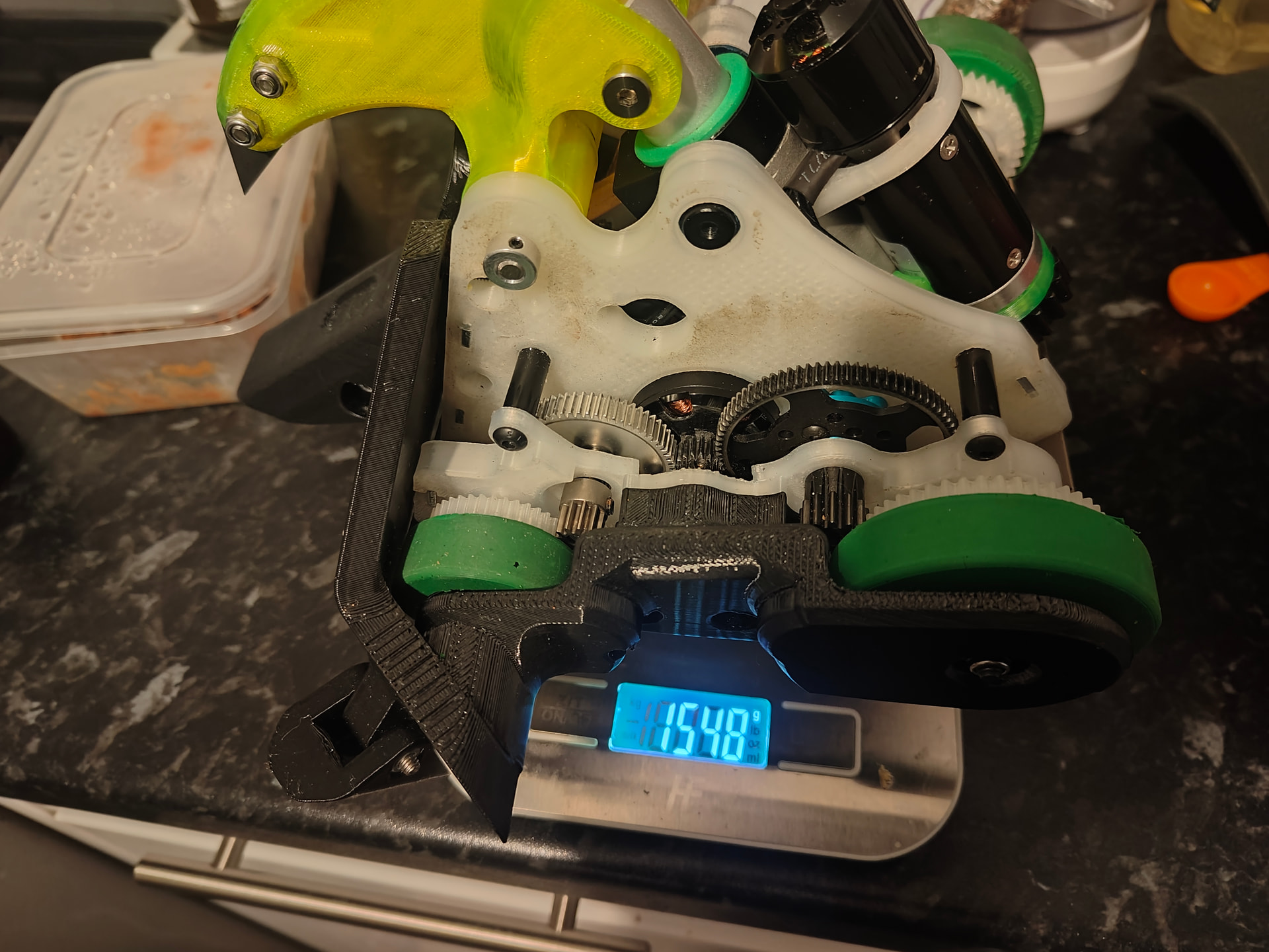
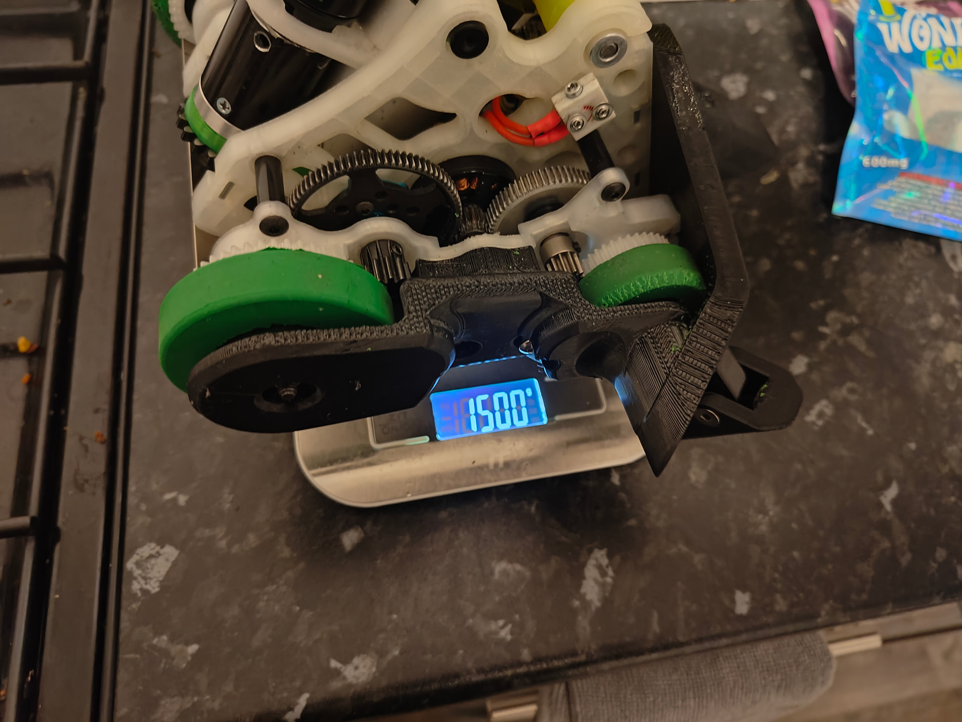
This was the moment I had got everything I wanted to into the robot and made the foolish mistake of plopping it on the scales.
1498g wow! Nice! 2 grams to spare!
What was less nice was I had to fit two lids, one 8mm shaft, a dozen bolts and screws, a weapon ESC and a switch into those two grams. That was going to be difficult.
In all honesty it probably could be done with enough flesh cutting and titanium shafting, component swapping but that all started to look like either an expense, a compromise or an expensive compromise.
Luckily, because I’m awful I already have solved this problem before. I had made several test beds to service an enormous horizontal that had a kilo of spinning mass and so had a lot of the necessary hardware to entertain an adhoc shuffler refit.
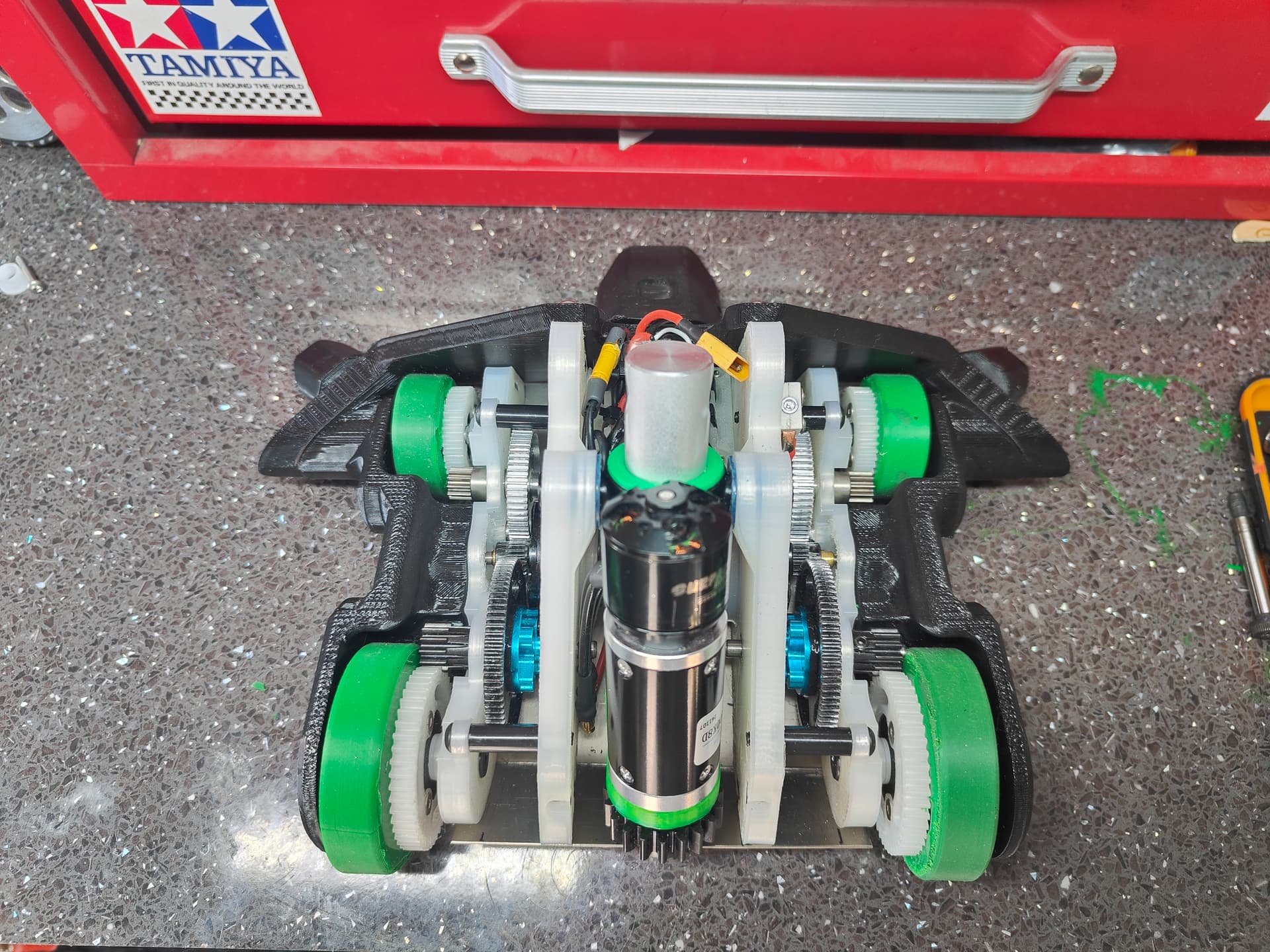
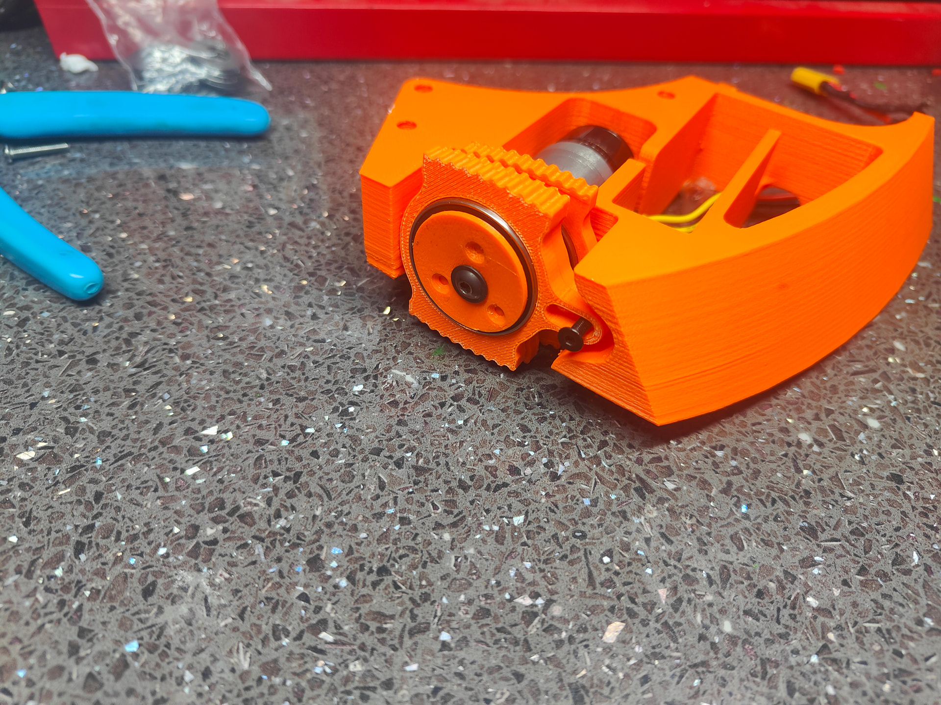
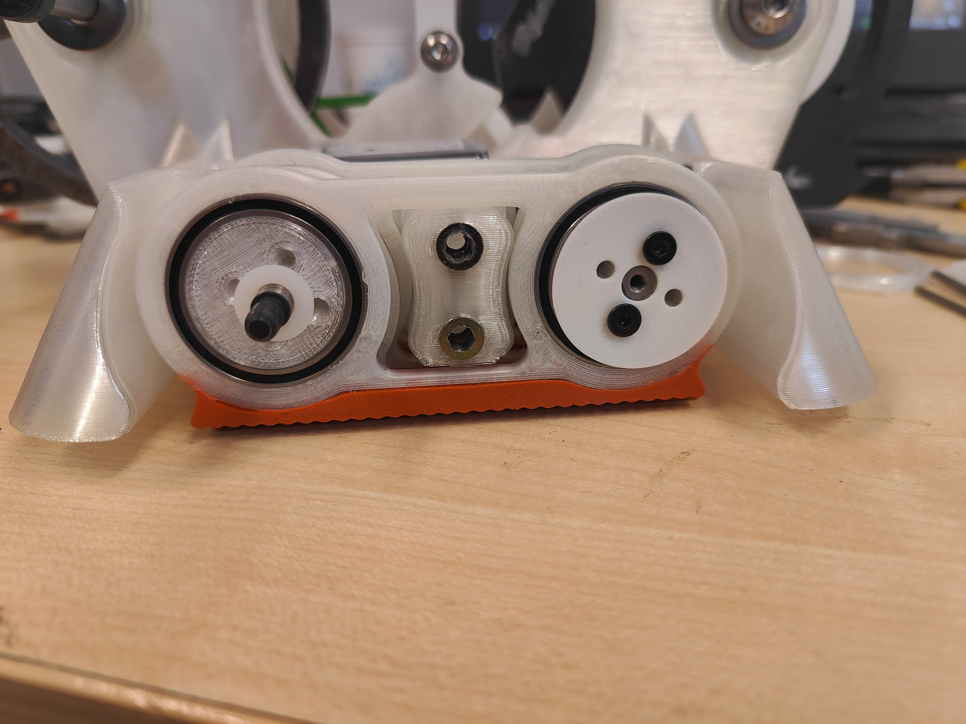
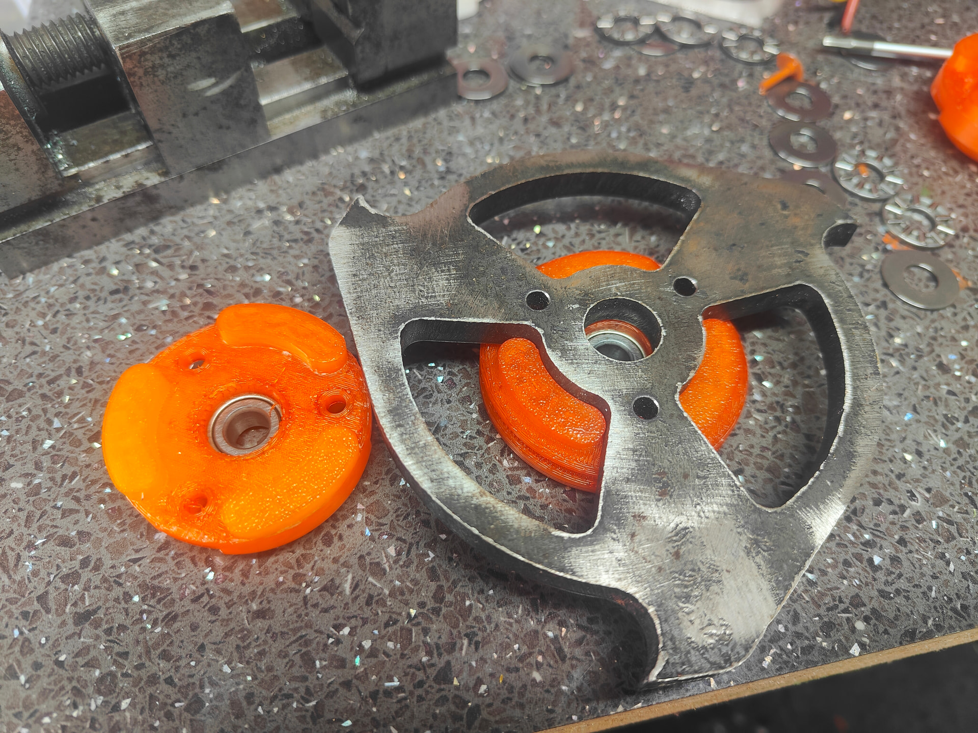
This was a little 3 cam offset leg that was really pretty low profile. There’s something exceptionally pleasing about 120deg spacing on this. Made really simple by the hex hub. I wanted my motion to be as smooth as possible and to properly fill out the space intended for the tracks I could fit 4 cams and 4 legs.
There! You’d almost think I designed it like that. It was a really good fit for the first draft and the leg design didn’t actually change too much from #1
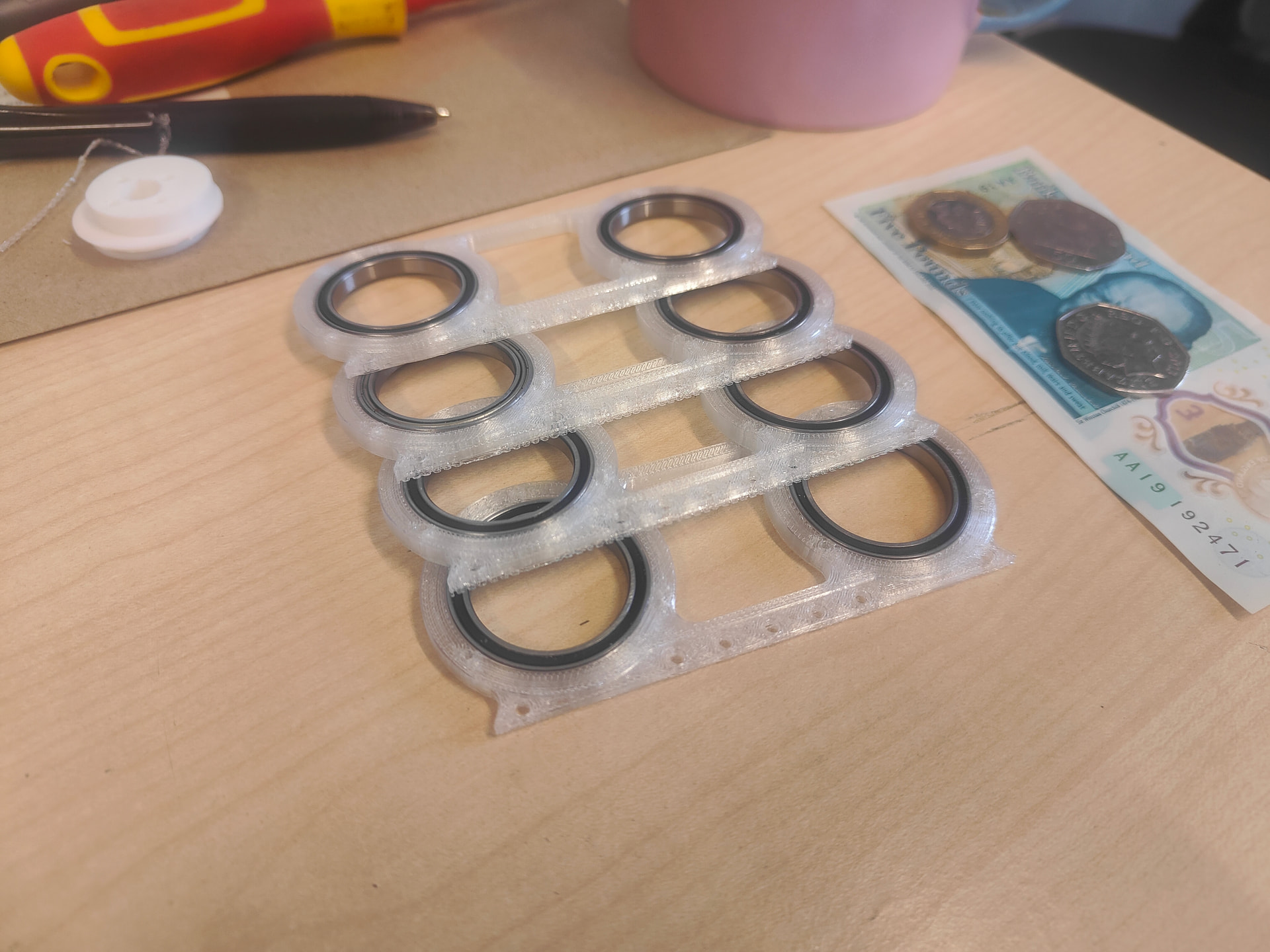
With the PLA trials done I added in my geometry to cast the tread around and hit print! These were done in the same TPU as the chassis and were an abject failure. Way too soft and flexible - they looked the part though. I quickly reprinted them in nylon. The bearings are a really tight fit, but there are also screw holes around the bore with the idea you can use a flanged head as a mechanical retainer.
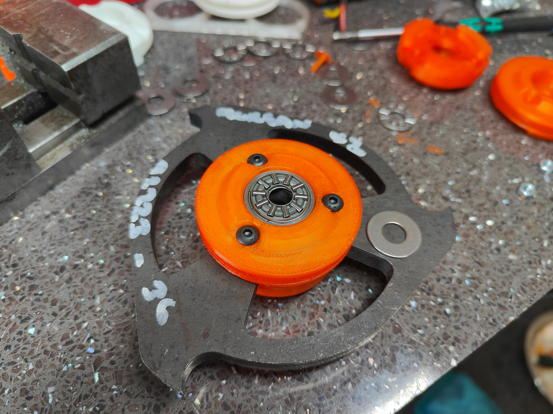
The ‘timing’ of the legs is done with the help of a MARS hub from ranglebox. The 2x offset cams are through bolted together and put at their 90 degree spacing using the hub. The driven cams are just pinned together mirroring the driven ones. The bearings are 25*32*4mm and there’s a lot of them. Gobless AliExpress. The driven cams run on Ranglebox nylon bushings - this works better than expected. I was stopped from using ball bearings by the PCD of any sensible screw pattern. I could use a needle roller but that’s expense that seems to not be completely essential for the moment.
It’s a bit annoying but all 4 cams are unique - with that old style 3cam it was one part replicated. If I wasn’t retrofitting it I think it could go down to 2 or 3 parts.
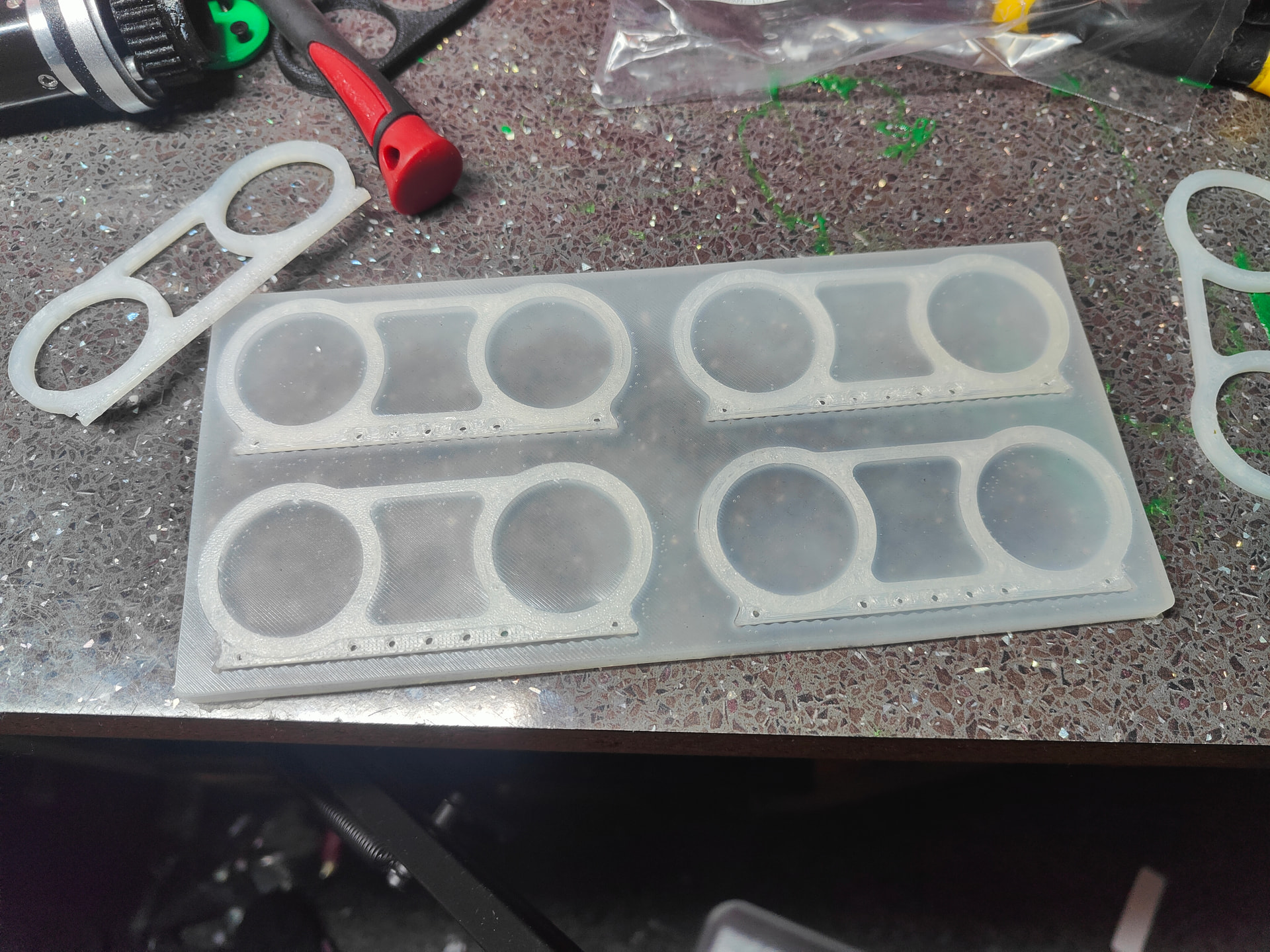
It wouldn’t be a Harry Post without a completely needless slab of silicone. I can’t help it, I just think they’re neat!
I printed a block of the legs with the tread on them and made my silicone negative where I could then slot my legs in and carefully pump them with 50a polyurethane.
This is the smallest and most delicate thing I’ve molded and it’s the most stressful, difficult and wasteful. Because I only really need 2.5g of rubber per foot I don’t technically need that much but I’m making 100% extra just so I can get it into the syringe. You can’t reasonably pour these moulds either. The technique is to gently fill them with a syringe, backfilling them via the through holes in the leg. It’s satisfying watching vibrant orange bloom through the shape but not easy if you have the sausage fingers of a particularly dense neanderthal and the dexterity to match.
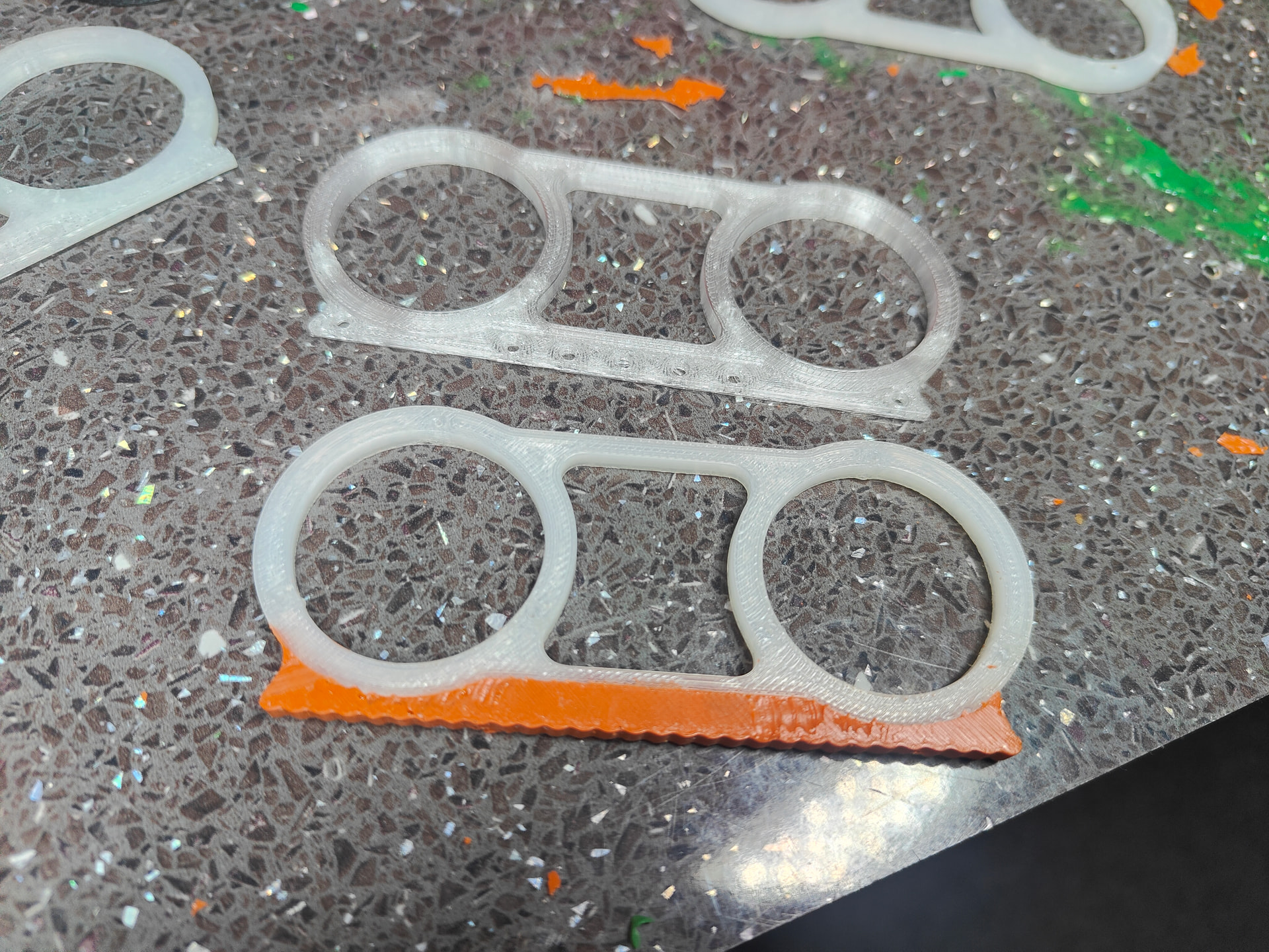
And that brings us to the false ginger moustaches!
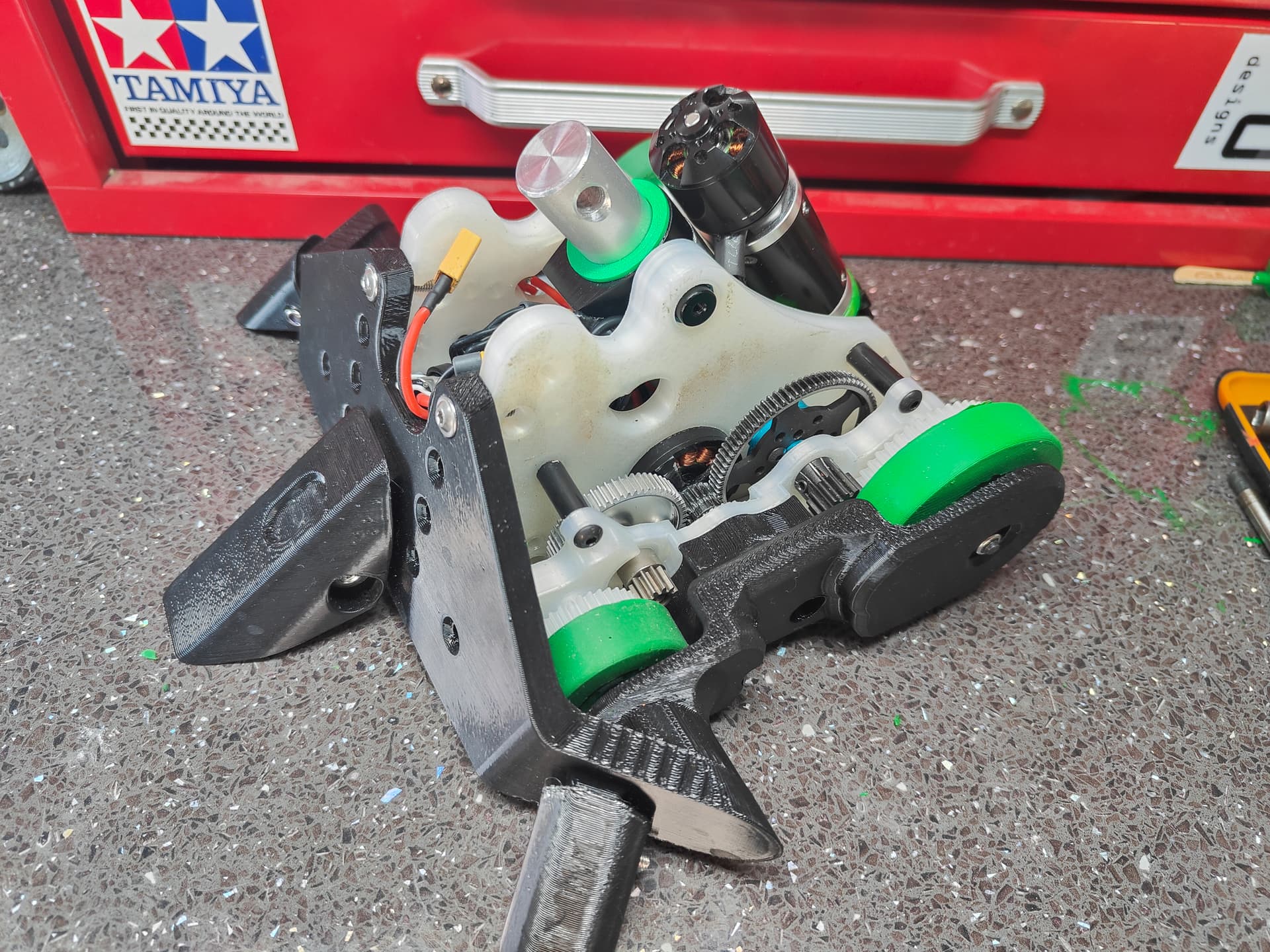
So you can see here now relatively tight the mechanism sits. You may call it an insulting lack of clearance but I say it’s an interesting and effective filling of usable space. The cams have a 2mm ‘stepover’ which lets them clear the inside of the track cutout.
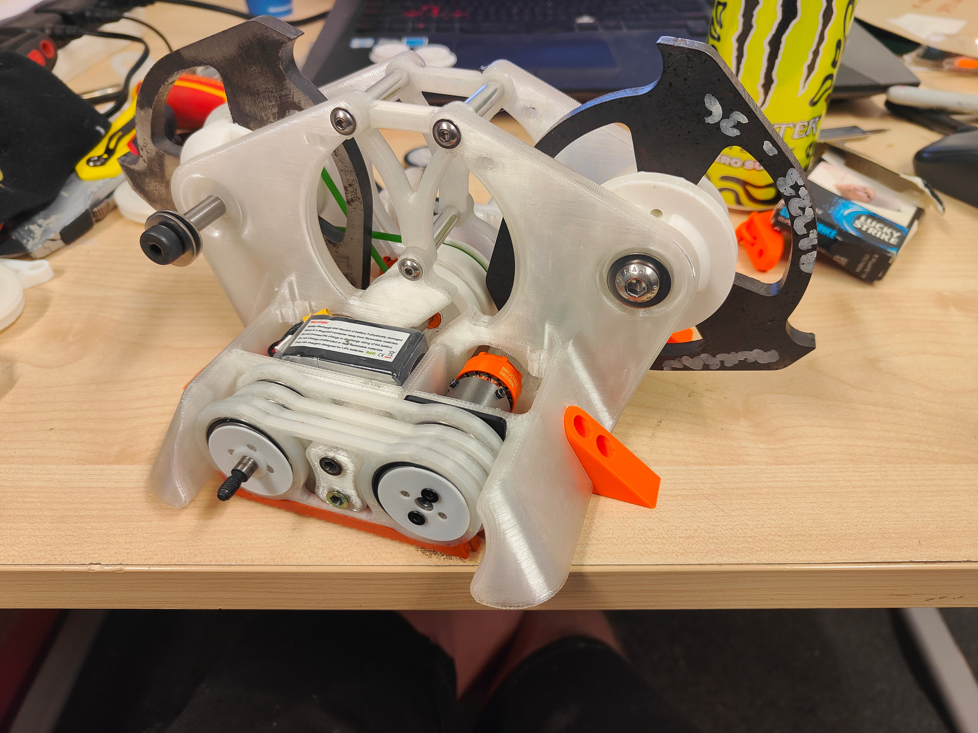
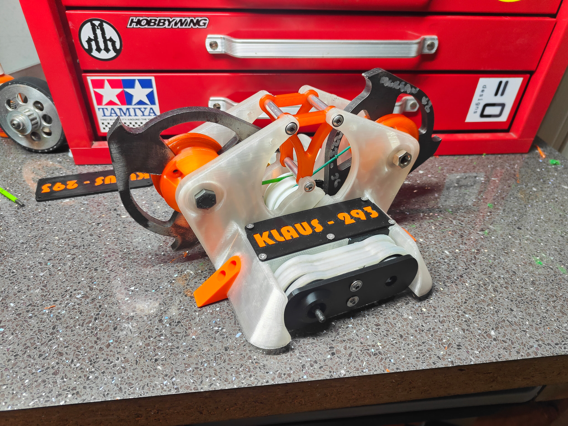
A closer shot of the rest of the robot coming together. It has these TPU forks that are fractionally pressed into the ground by the elasticity of the material so that any frantic jiggling by the locomotion doesn’t pull them off the floor. This also shows the addition of the nylon brace which is there to make the robot look like an old bridge (please, call me Isambard Kingdom Hills) and more importantly stop the flexible nature of TPU from causing immediate and catastrophic damage the second it hits anything.
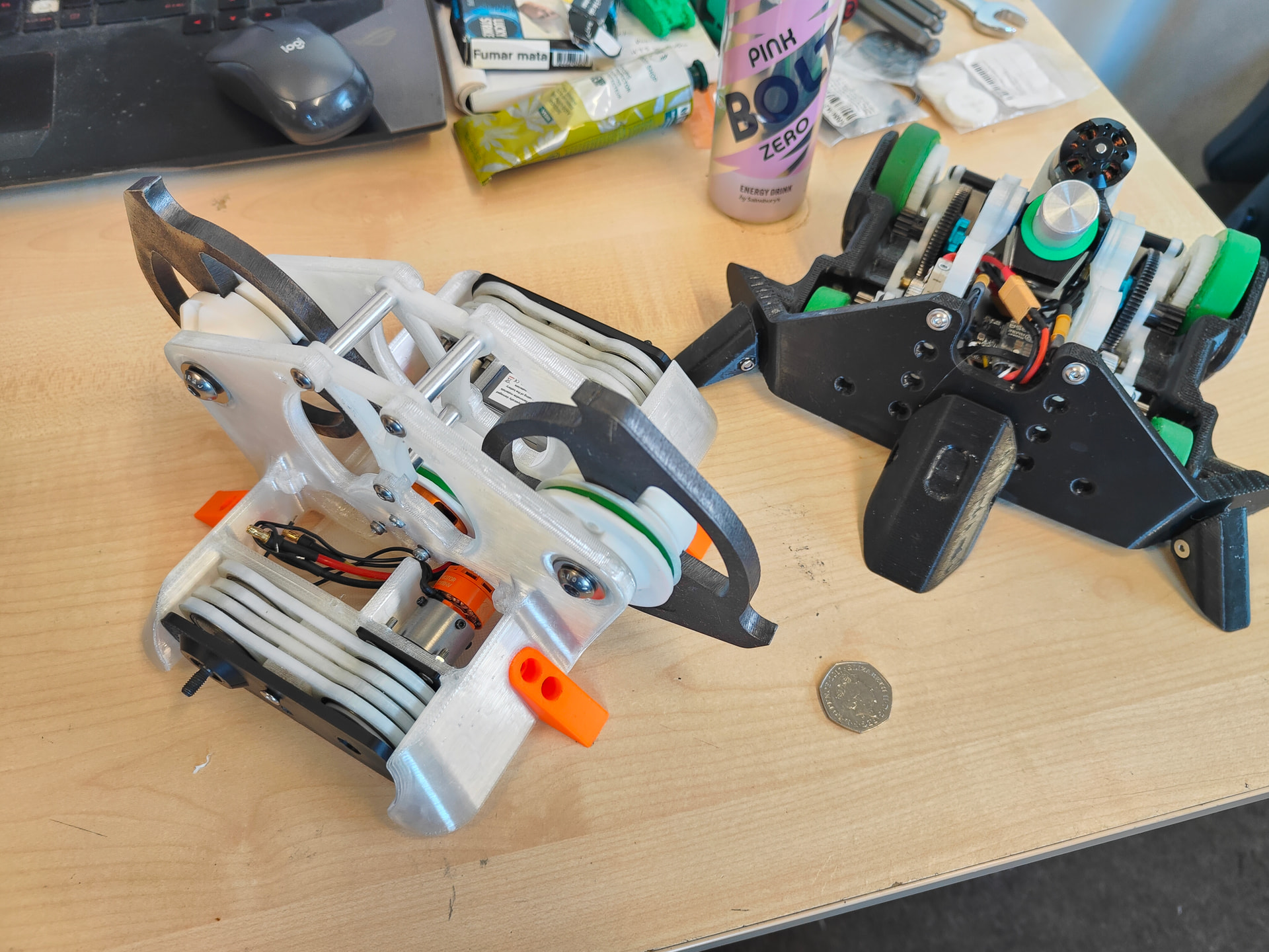
In case you needed some scale for Klaus-293 it’s only slightly larger than Nips, sharing almost exactly the same footprint. Very different and incompatible vibes however.
Again, it wouldn’t be me if there wasn’t an element of dyeing my fingertips a funny colour, alongside some nylon as a byproduct.
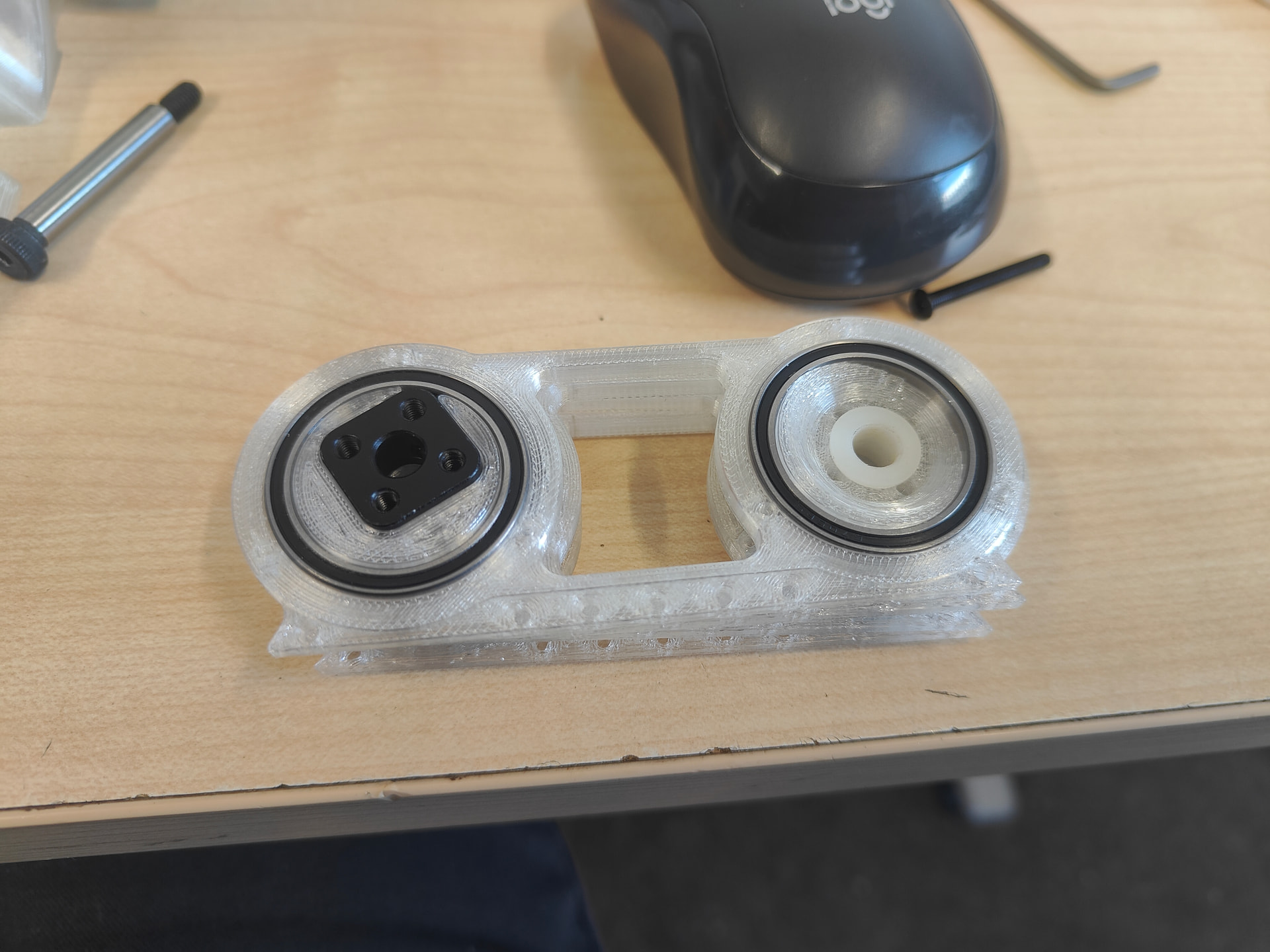
The pulley and hub interlock with the spokes of the disc which means that the bolts (only 3*M4) aren’t taking all the shear load and it really helps from a quick alignment perspective
The assembly isn’t the sexiest or most interesting of affairs truth be told but it’s sort of an attempt at best practices within less than ideal constraints. There are two 8mm bearings, spaced out as far as possible but still having proper thrust bearings. They will run on a shoulder bolt that I can just torque the assembly down and get a really solid install.
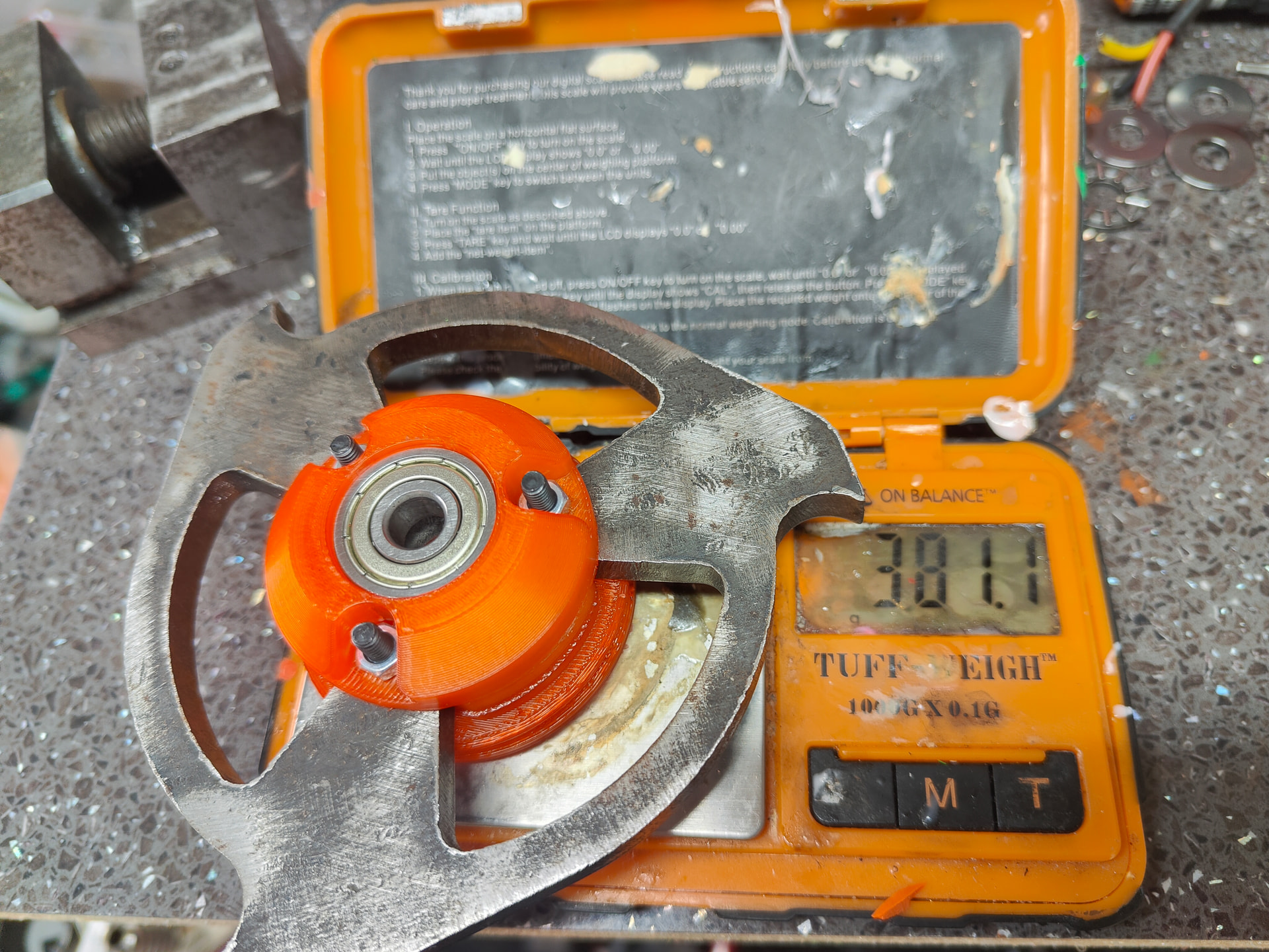
Minus a gram or two for bolts that are the right length and that’s still a chunk of change for a weapon - and I’ve got two of em!
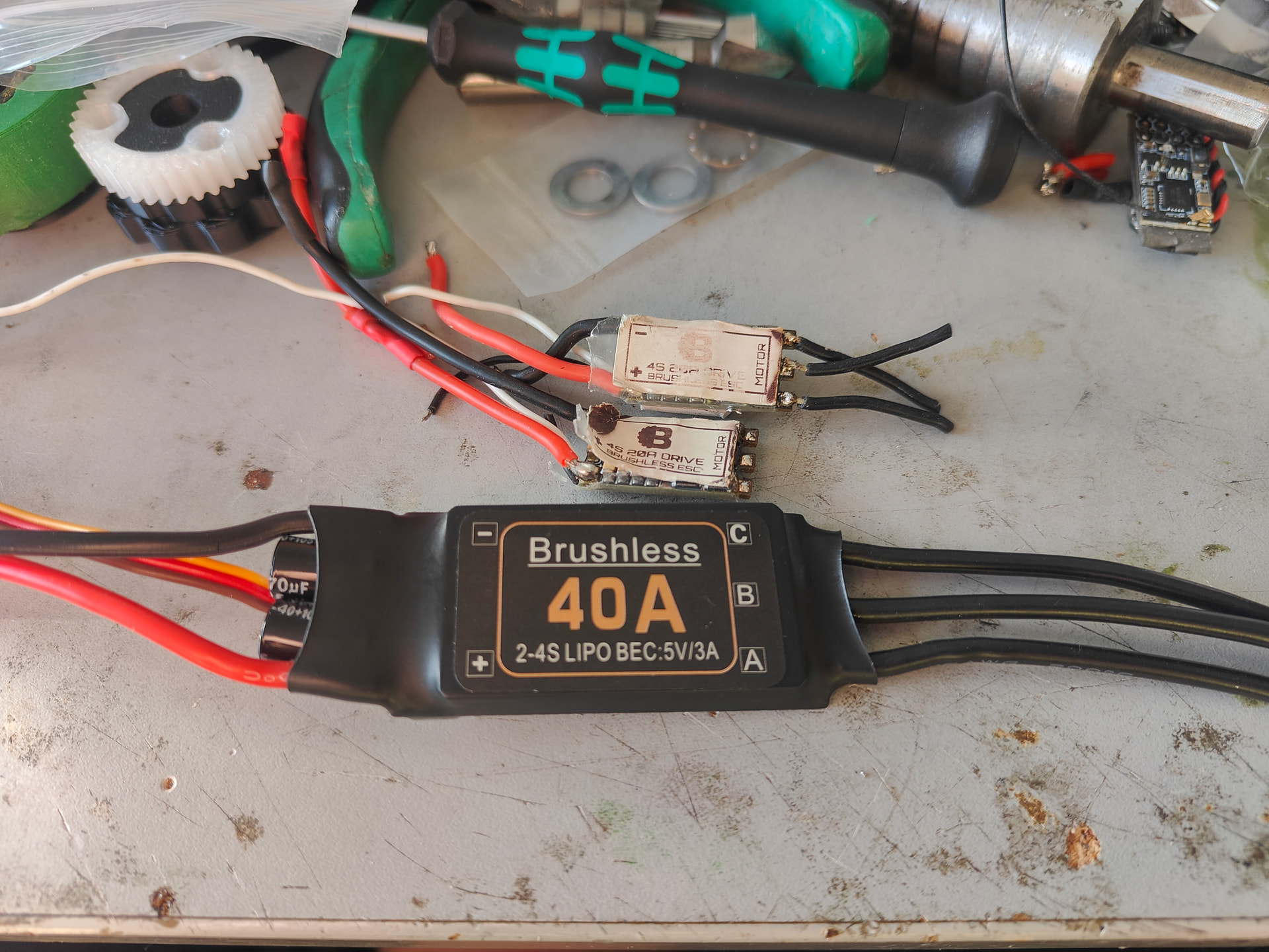
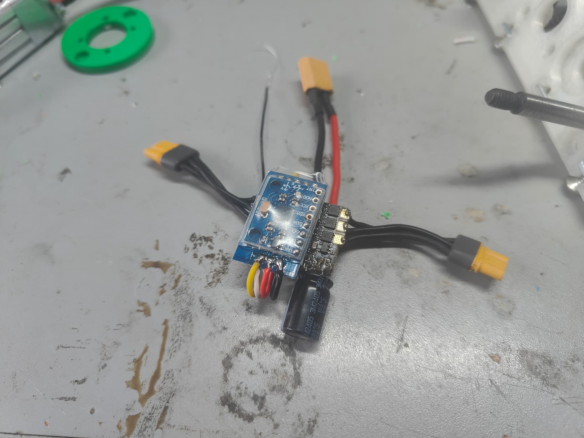
So that’s the guts of this little nugget. Reuse, recycle and so on. Some very well loved BBB brushless escs and a £3 genuine Bottom of the Barrel Borshless (different type of BBB) plane style ESC. Back in the day before drones ruled the skies, phat mosfet spammed plane escs were a completely legitimate way of controlling motors. Too dumb not to work is the theory I’m working on here.
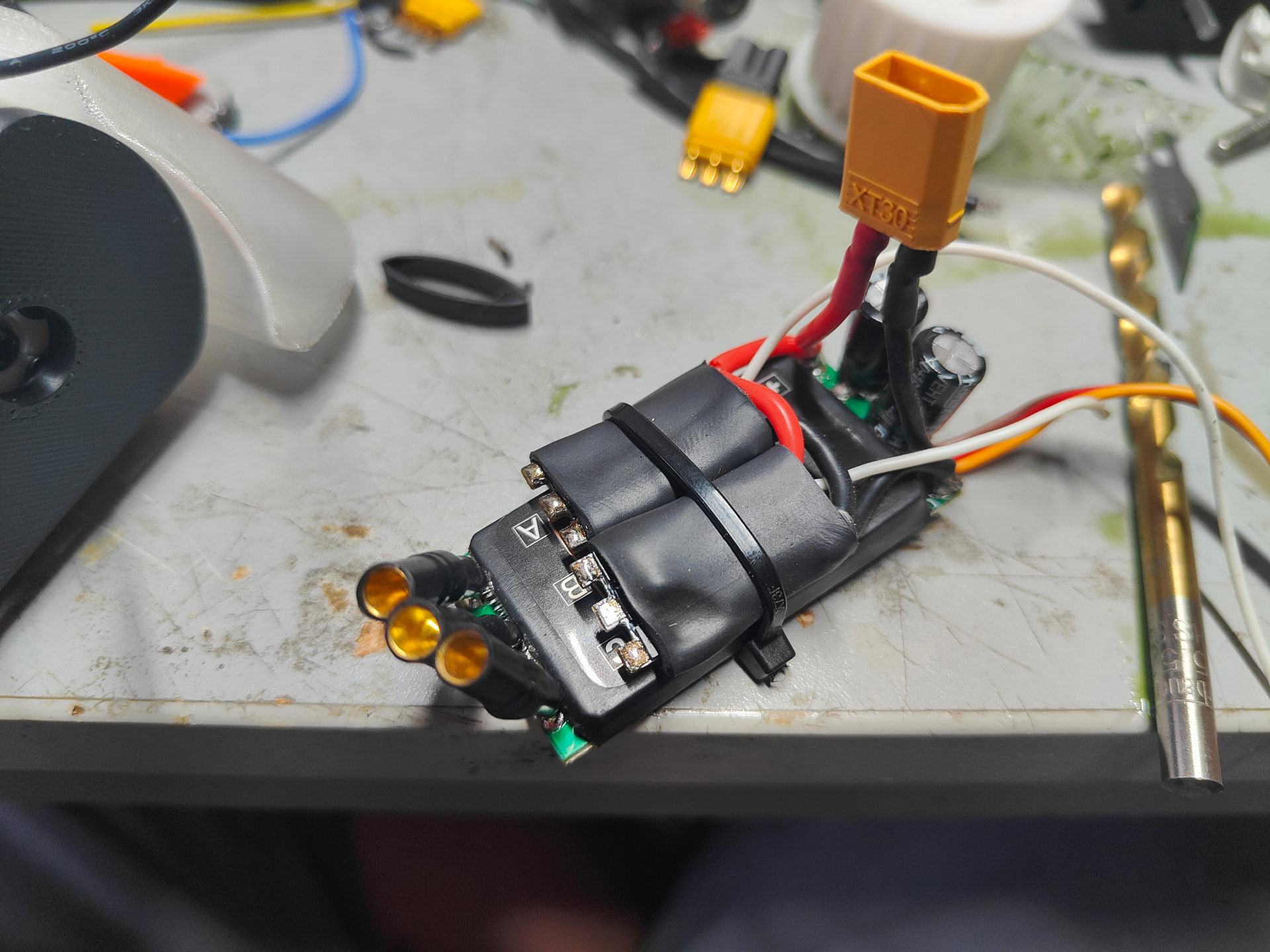
Here it has been chopped and glopped together with a liberal application of heat shrink, zipties and several warcrimes against electrical engineering.
Well, there we have it. Some work still to go on, mostly detail oriented and tightening and testing but it’s all together. Not bad for a little low effort side quest.
As stomach churning as it is to publicly state your own pride in a build I’m genuinely really happy with ole Klumpy here. It was a nice refresher into a lot of old habits and I can still try and trick myself into thinking I have an artistic flair. ( That’s ARTistic, people)
There’s still a lot of weight to play with so I’m guessing I’ll start beefing the lids and the side armour as a start but I’m kind of happy just to let it ride.
Now comes the question what do I actually do with this lump? I am dead set on Hard Nips being the next robot I compete with so it’s sort of going to get relegated to whiteboards which I don’t think is fair for this sort of robot. Already at a mobility disadvantage I feel it could hold it’s own in a 3 way melee but not against anything more serious.
See what the calendar looks like for the year and hope to get it wiggling it’s way out to something!
I’ll leave it on the specs for now and think about it further.
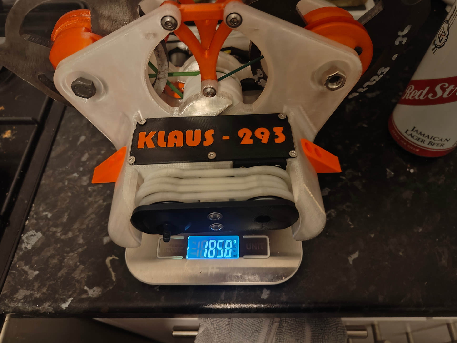
KLAUS-293
Dual vertical spinner with shuffling mechanism weighing ~1860g driven by 2x MARS gearmotors on 4s. Weapon is 770g split over 2x 8mm hardox discs with a 238mph tip speed powered by a generic 3530 brushless. 650mah 4s battery, BBB brushless escs for drive and unknown 40a brushless on weapon. Chassis is a TPU monoblock with nylon and ABS bracing.
P.s. If you can guess where the “293” designation comes from you have the same strange interests as me and I’m glad you’re out there.
7 Likes
Something to do with that one big vert that was in series 6/7 (wow I’m such a comedian) of robot wars?
If it’s called 295 (or 259 possibly), 294 would be a feather and 293 would be a beetle.
Wrong!
Good shout but I have a different sort of brain and forgot 259 was a robot.

It’s named after Bagger 293 which I adore as an engineering marvel. The profile of the spinner bulkheads and the bracing was slightly inspired. If only I could have kept the tracks.
4 Likes
if you had kept the tracks then it wouldn’t be a beetleweight!
A lovely build and a great writeup too Harry. Thanks for taking the time to document it!
To be fair with 2x 4mm discs or a weight conscious 6mm it would have been easy to keep it under 1.5kg
Thanks for the kind words @McMullet !
So I’ve sobered up from the unstoppable rollercoaster of seasonable debauchery that constitutes a British Christmas and New Year and after clearing my inbox and doing some maintenance on the printer I decided to test it out with something Nipsy.
This jaw fits a tiny Hardox insert tooth that is from one of the vestigial Nipsisises that didn’t get completed (the one with the cool folded aluminum jaw!) it’s just TPU which will dampen the squashing somewhat but also will let Hercule Nipoirot get smashed in the face more easily without suffering too much.
Speaking of taking a roundhouse or two, I’m ready to jump back in the ring with my old sparring partner. The Weight Limit. And boy does he not pull his punches. In my heart of hearts I knew I was going over sooner or later but it’s a blessing and a curse to have it come at this point.
48g isn’t impossible by any stretch to cut but reasonably I need to pull closer to a hundo out so I can get some extra trinkets in place to complete the vision.
I have options, making the central bulkheads polypropylene would do it, changing everything from a steel shaft to titanium or even carbon (loving how much RC car there is in robots atm! Who says my beetle can’t also be a TA-02 just assembled differently)
One of the fun aspects is when I’ve already been conscious about weight every individual part is already pretty light! You’re never going to pull 15g out of a 30g part the same as you would a 100g. I’ll be looking to skinny down the actuator gears and potentially the ring gear (though there isn’t as much in it as I hoped)
Dropping a stage would do it immediately - losing a lot of crush but gaining grab and getting me a potentially neater assembly. Tossing up if a smaller motor might also be advantageous too. Quad stuff is smaller and angrier bit often has the price tag to match and 4mm shaft might be tricky.
4 Likes
That children, is what we call a '"Lie”.
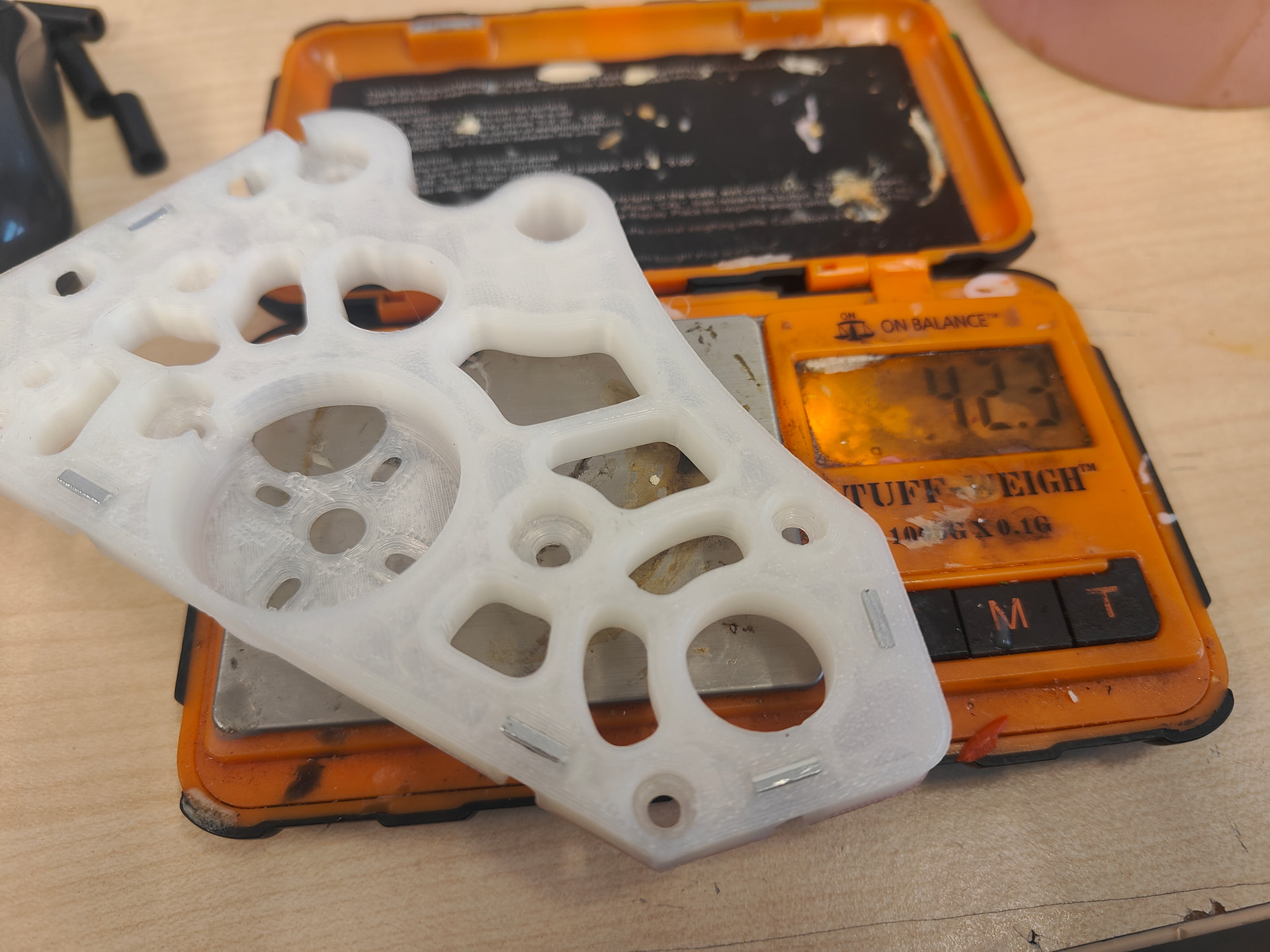
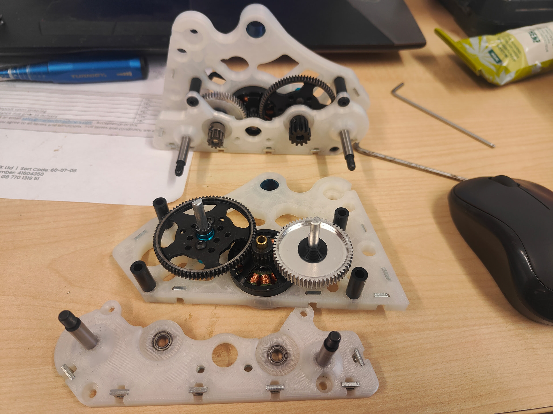
So I cut weight for my central bulkheads by a third and was able to ramp up the wall count so it’s potentially stronger too. The turning for Diminishing Returns was about 5 miles back so I’m just carrying on regardless. I quite like the skeletal effect, though it doesn’t have my usual (lack of) panache.
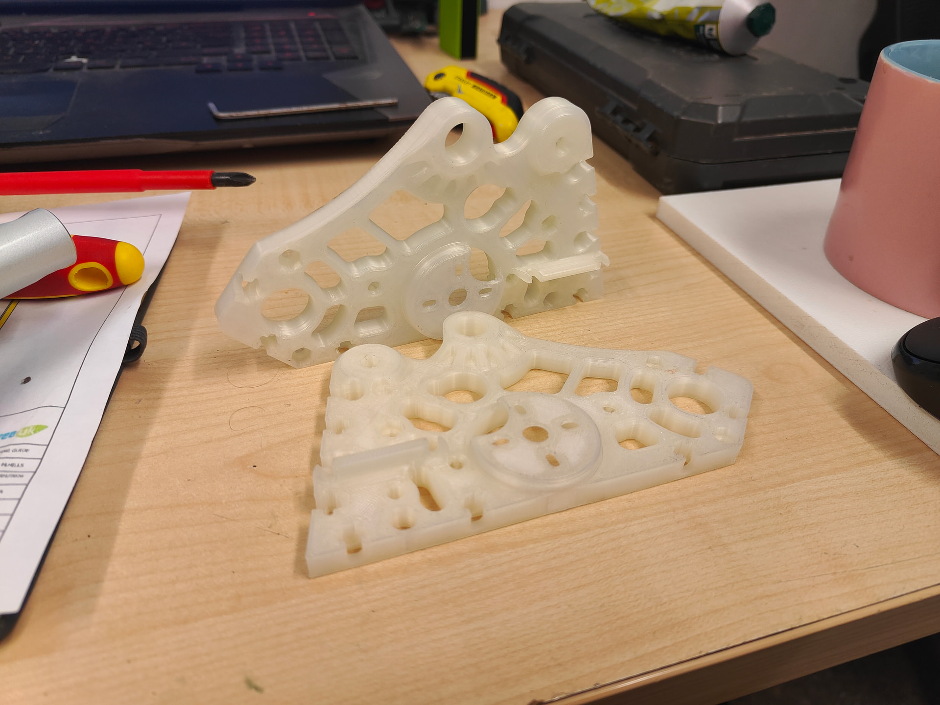
Spiffy, I’ll get them populated with fixings and such shortly. I’m actually reprinting these now with some tweaks as these are a bit too spindly (wrong infill style, less walls than I really want) but I just ran out of Nylon. Amazon to the rescue so I should have more tomorrow.
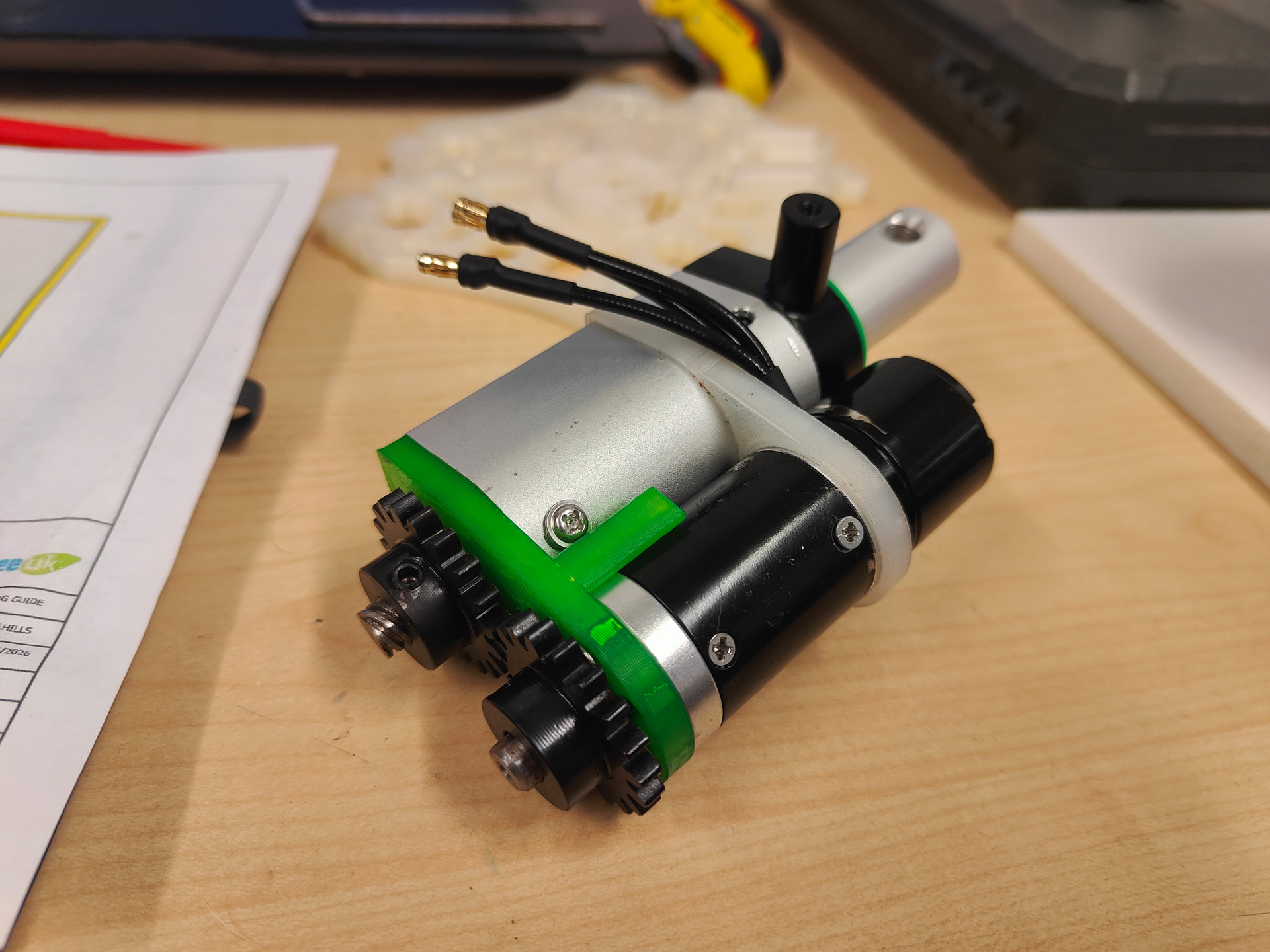
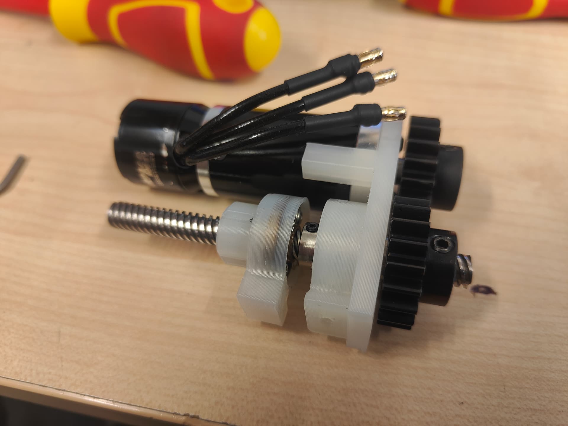
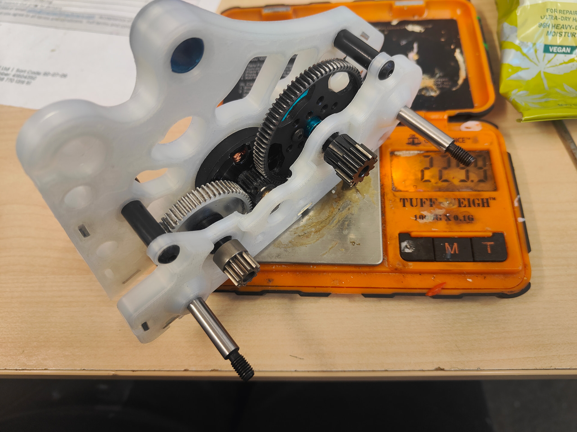
I washed the actuator on hot and it shrank! I basically actioned all the little ideas I thought about before. Gears have been narrowed down and I chopped a stage out of the gearbox. Criminal and I hate myself but it was probably best done now as it’ll make the difference down the line. Painful but sacrifices had to be made. This has taken all of the potential “crush” out of the robot but it’ll get it done and that’s what really matters.
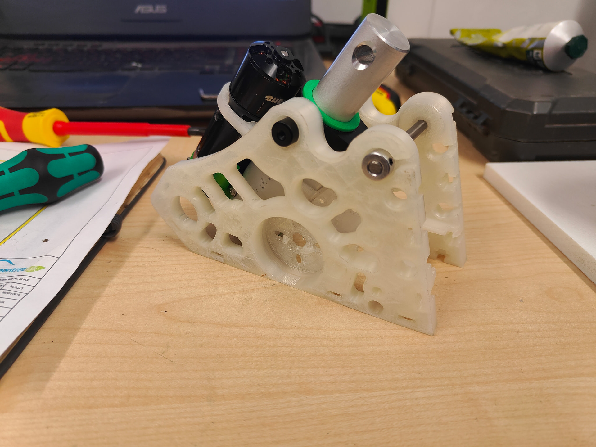
If all sits a bit neater and I think it looks a bit cooler as it stands. The steel bolt shaft has been replaced with titanium and shaft collars which sit in a little pocket.
I have some polished aluminum shafting (oo er) coming soon so I can ditch the last of the dirty, heavy steel and replace it with something less than half the weight. Gotta grab those grams somewhere!
4 Likes
The turning for Diminishing Returns was about 5 miles back
love that ![]()
new uprights look very cool too almost want them printed from something glow in the dark for a spooky feel
1 Like
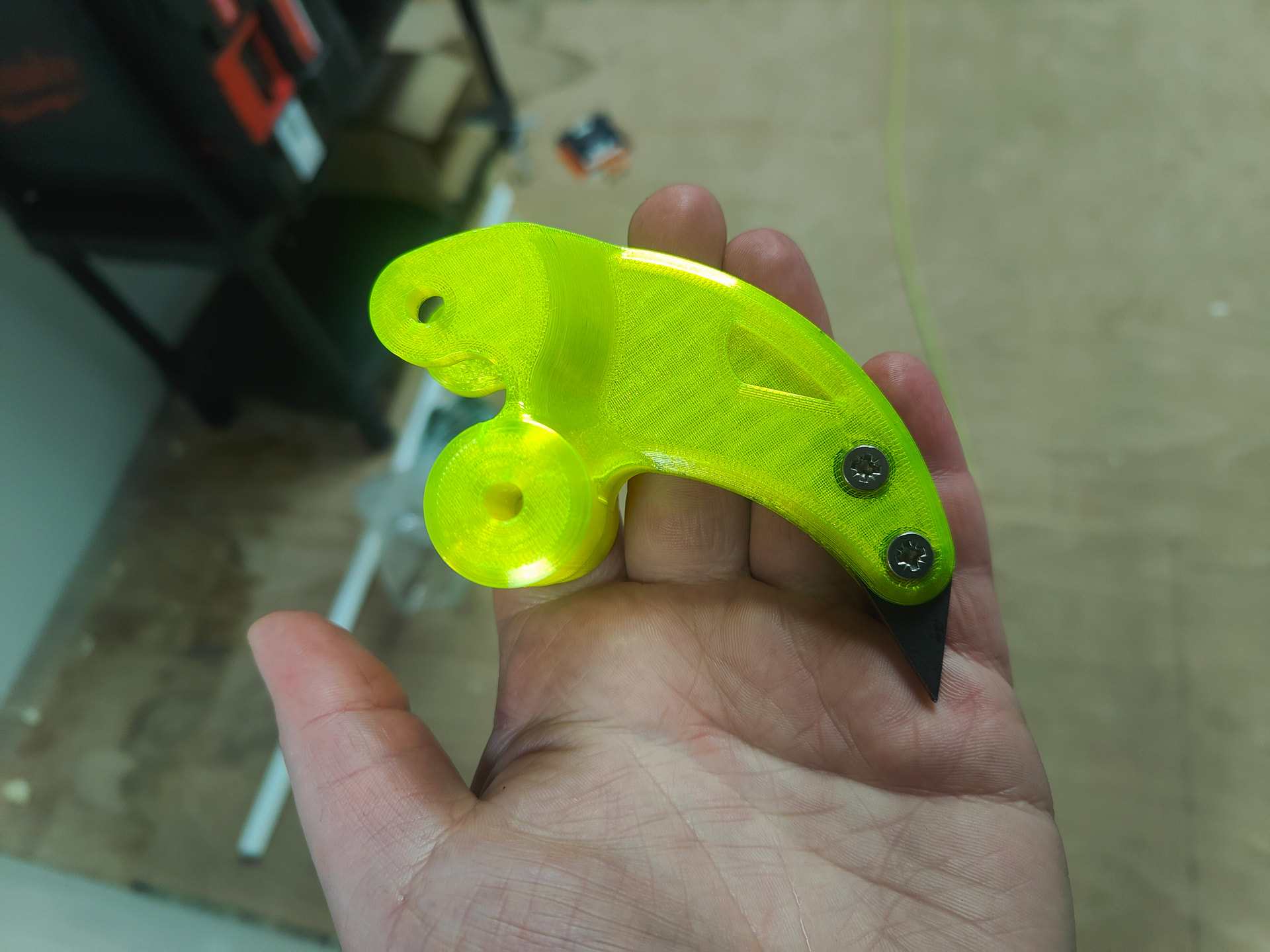
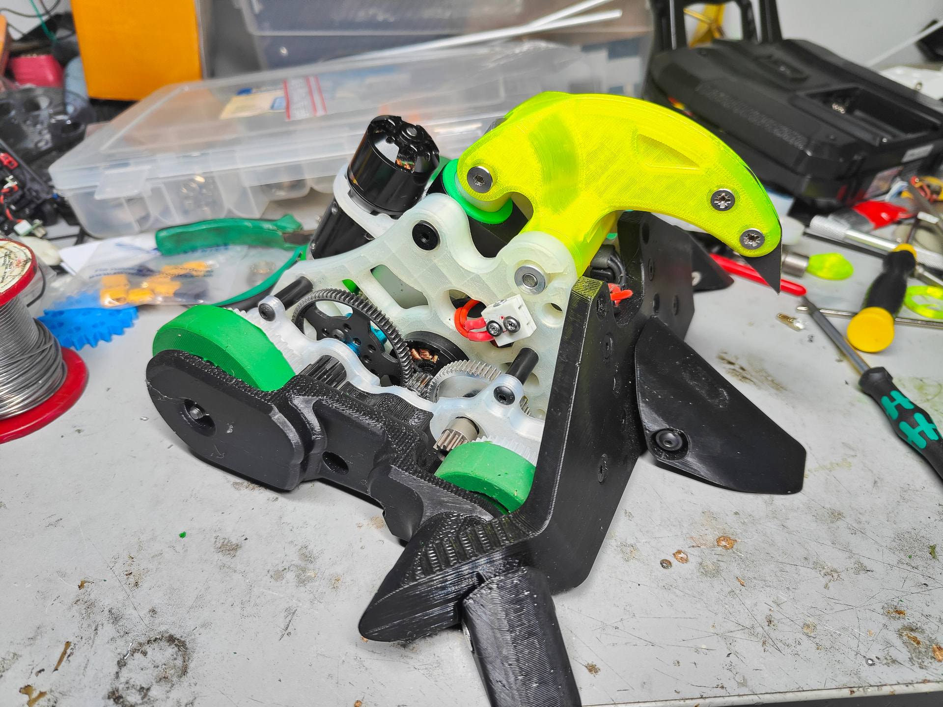
Aha yeah the nylon was a little infected by the very neon yellow TPU I have been using for other projects like this absurd nugget:
ANYWAY let’s not get undiagnosed adult ADHD get in the way of a good time, and what better time is there than the Hardest Nips in town.
I finally put a massive niggle to bed in the lack of constraints in the drivetrain. Everything is pin driven save the pinions which are grub screws but axial retention is lacking. A big enough knock would let the spur gears wibble forward enough that the drive pin would be centrifugally jettisoned and I would be left dead in the water spinning the gears on their shafts. These are just ABS plugs that space everything to the right distance.
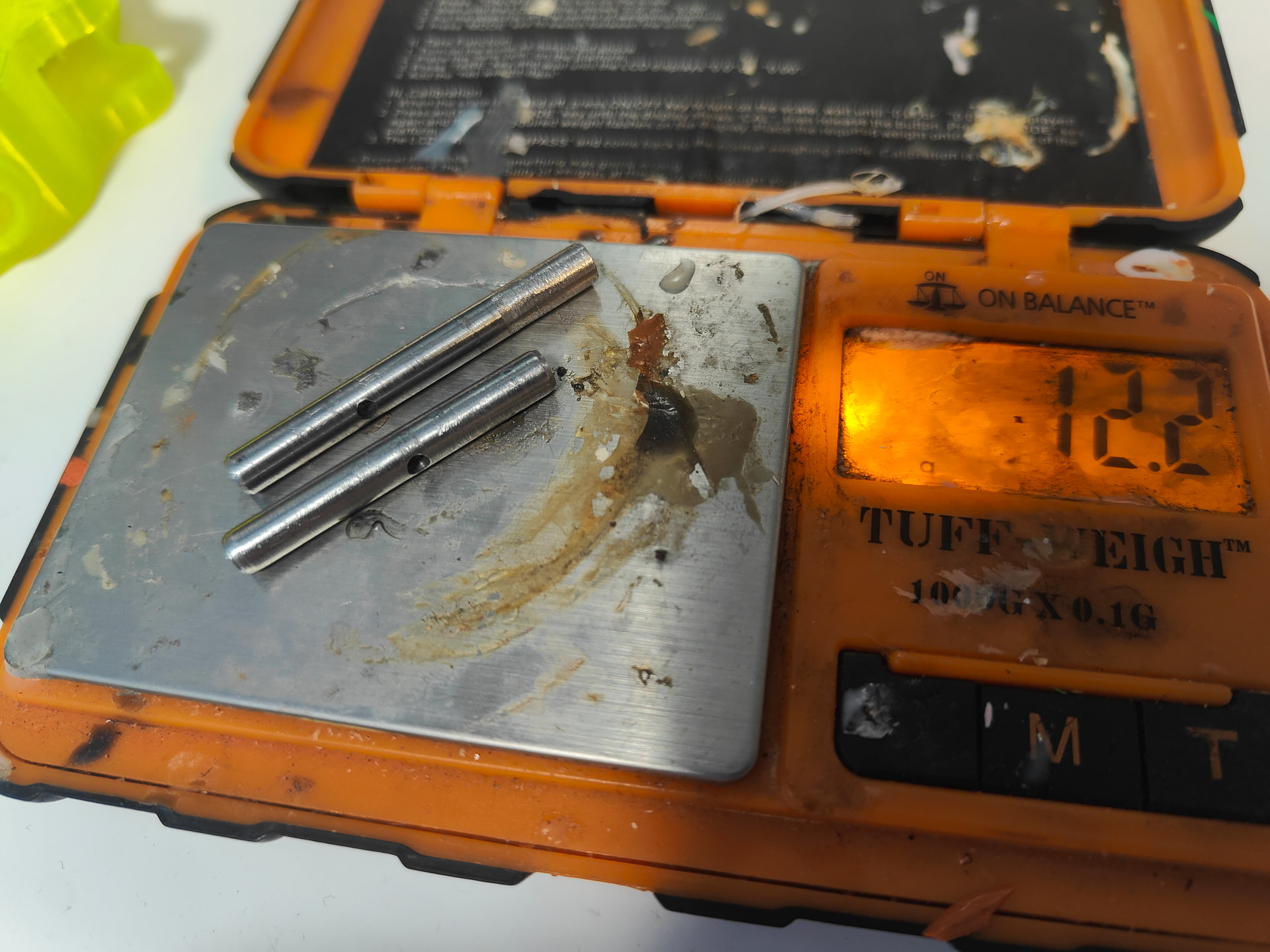
I have gone for Aluminium in the end as I found some polished 6082 rod which is good enough to wibble through my bearings. I have the material and I have the jigs but haven’t yet cut and drilled them so I’m still rocking the steel driveshafts. The 4 old ones weigh 36g which the new ones are calculated to be 11g
I also figured out my transmitter settings as Inpost lost my old faithful i6 so I’m having to use my GT5 pistol grip.

It will take a little getting used to but it’s functionally there. I’m missing the higher ratio in the gearbox but I can’t fault the sacrifice. Perfect might be the enemy of Good, but Good Enough is a drinking buddy of Completed On Time.
The jaw is a design version behind so it sits lopsided but I’m still not convinced by the material and shape. It’s far too compliant and the TPU is just deflecting like I worried it would. It’s also heavy - so it’s a candidate for material reassignment. I’m not convinced nylon is tough enough to take a haymaker on the chin but it might be going that way. HDPE is also in the mix with some printed shenanigans.
I mean - a week’s worth of effort for 48g. It’s not horrible? It gives me hope that I can get all that I want inside the limit. Every little helps.
My main areas are the TPU wraparound armour but that’s mostly a wall/infill tweak. Shafts as I said before will net me close to 20g. Beak could be a area of saving but I’m not overly hopeful. I need to find about 50 more grams, though a healthy 20g to spare is probably prudent.
2 Likes
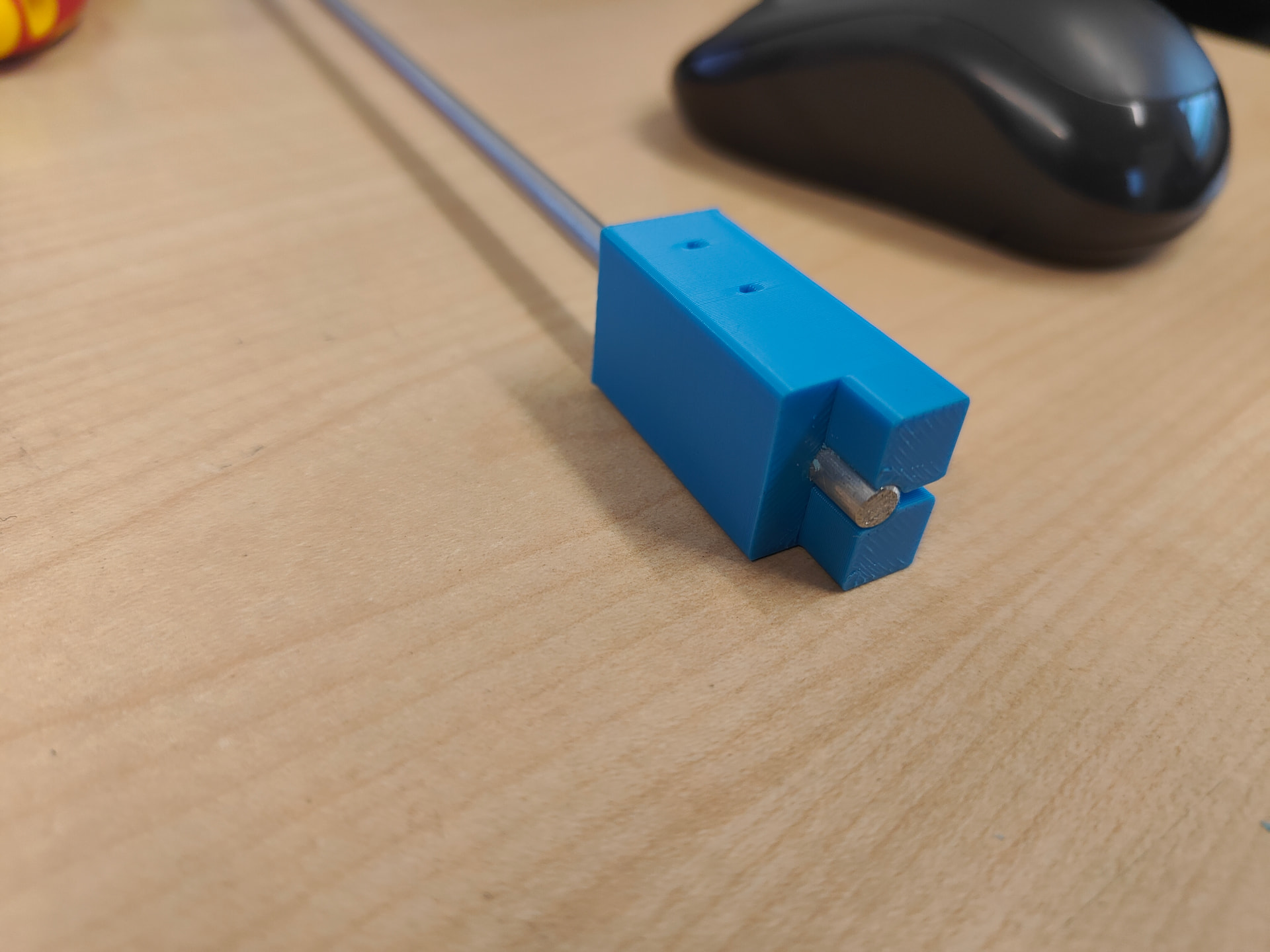
Printed myself a little widget (a dohicky, even) to make my driveshafts with minimum effort. The two holes let you drill the drive pin positions, both front and rear and the cut out at the front lets you put a flat on it. Then just chop to length and debur.
Mere minutes later I had some little stub shafts - this was almost too easy, might have to keep this in mind for future builds.
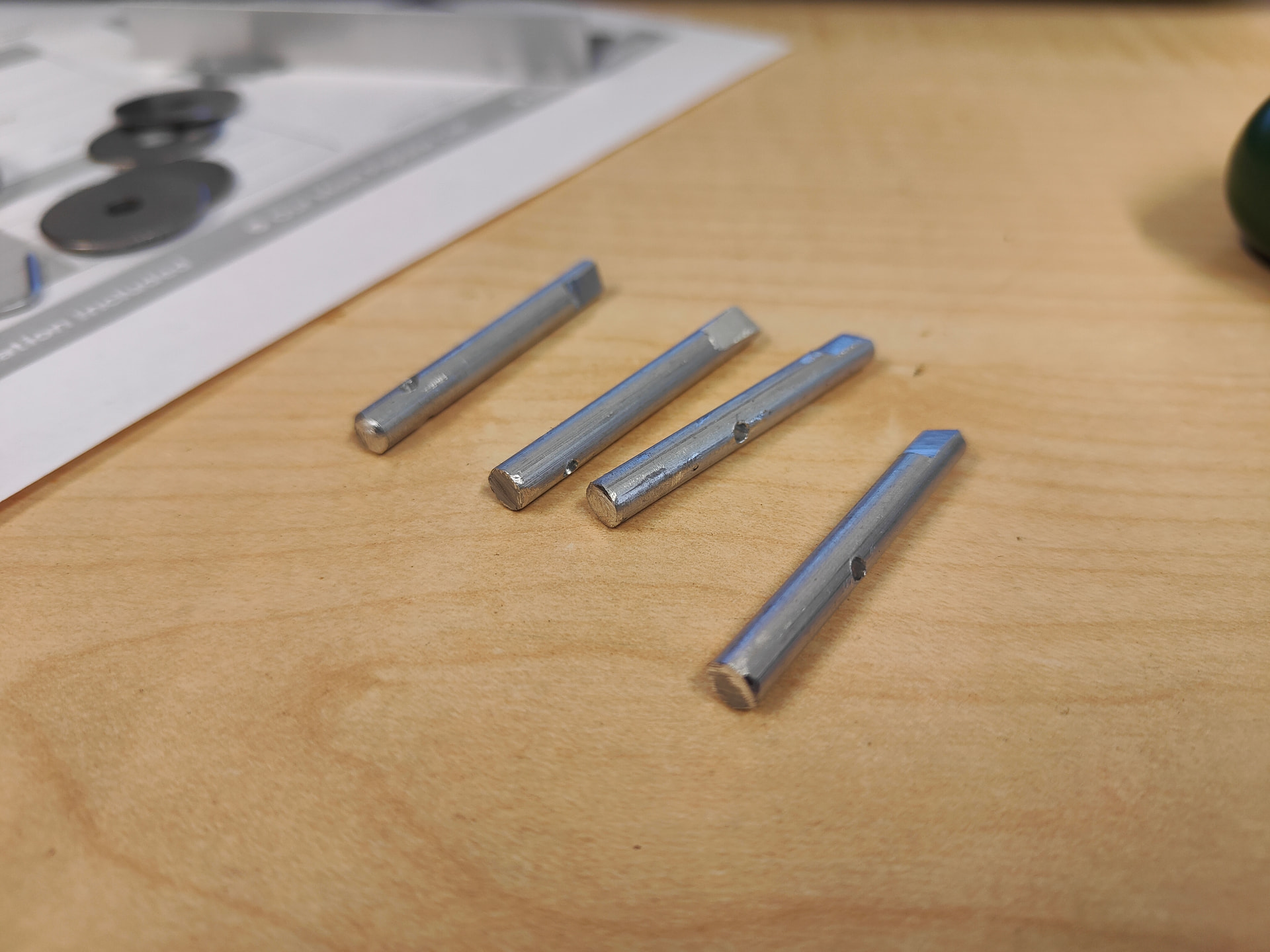
Comparison for the old shafts
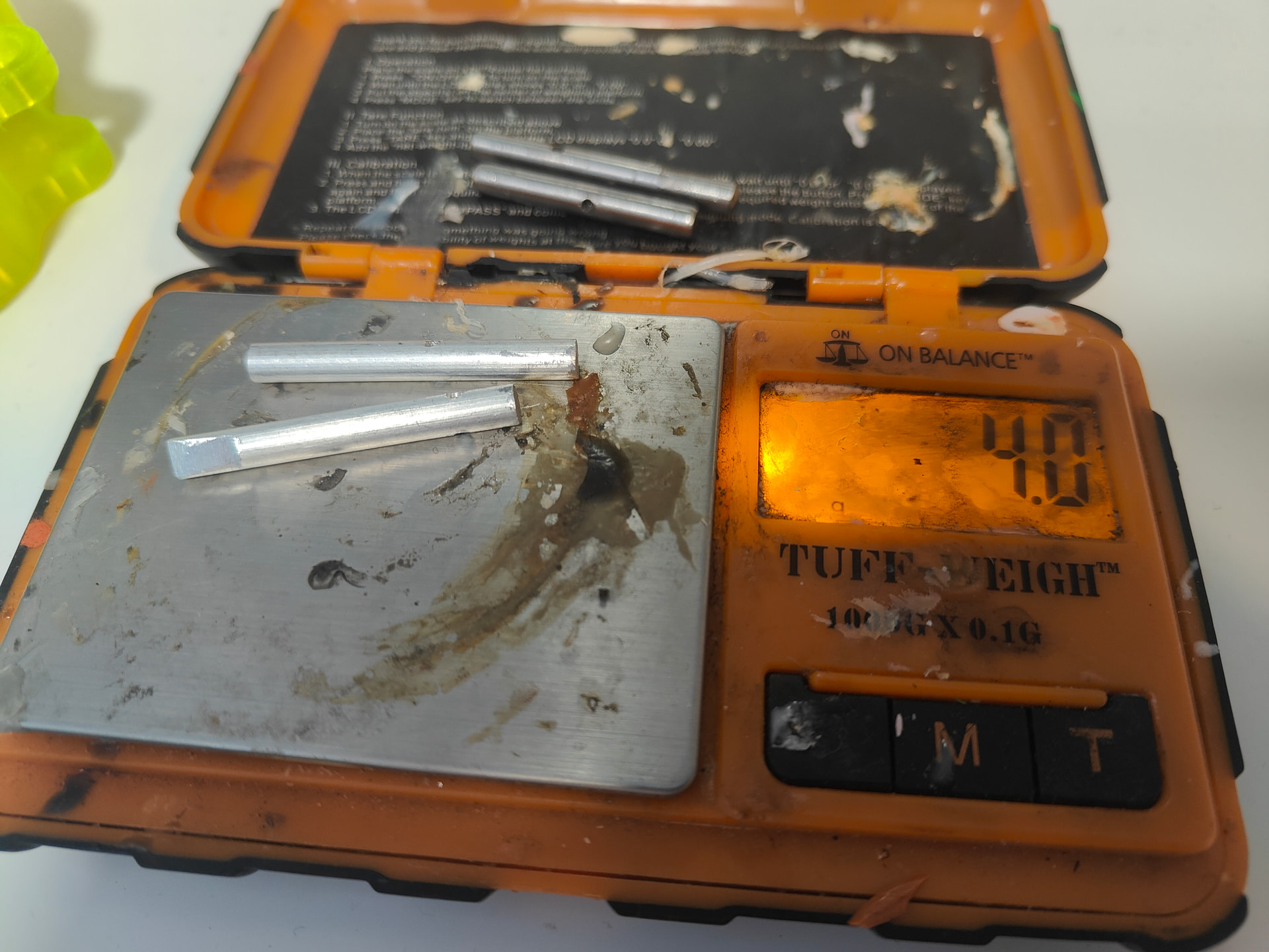
And the new - lovely saving there. Hopefully they’ll be strong enough! I wouldn’t chance them in a direct drive shaft but for my use case I might skate without wonkification.
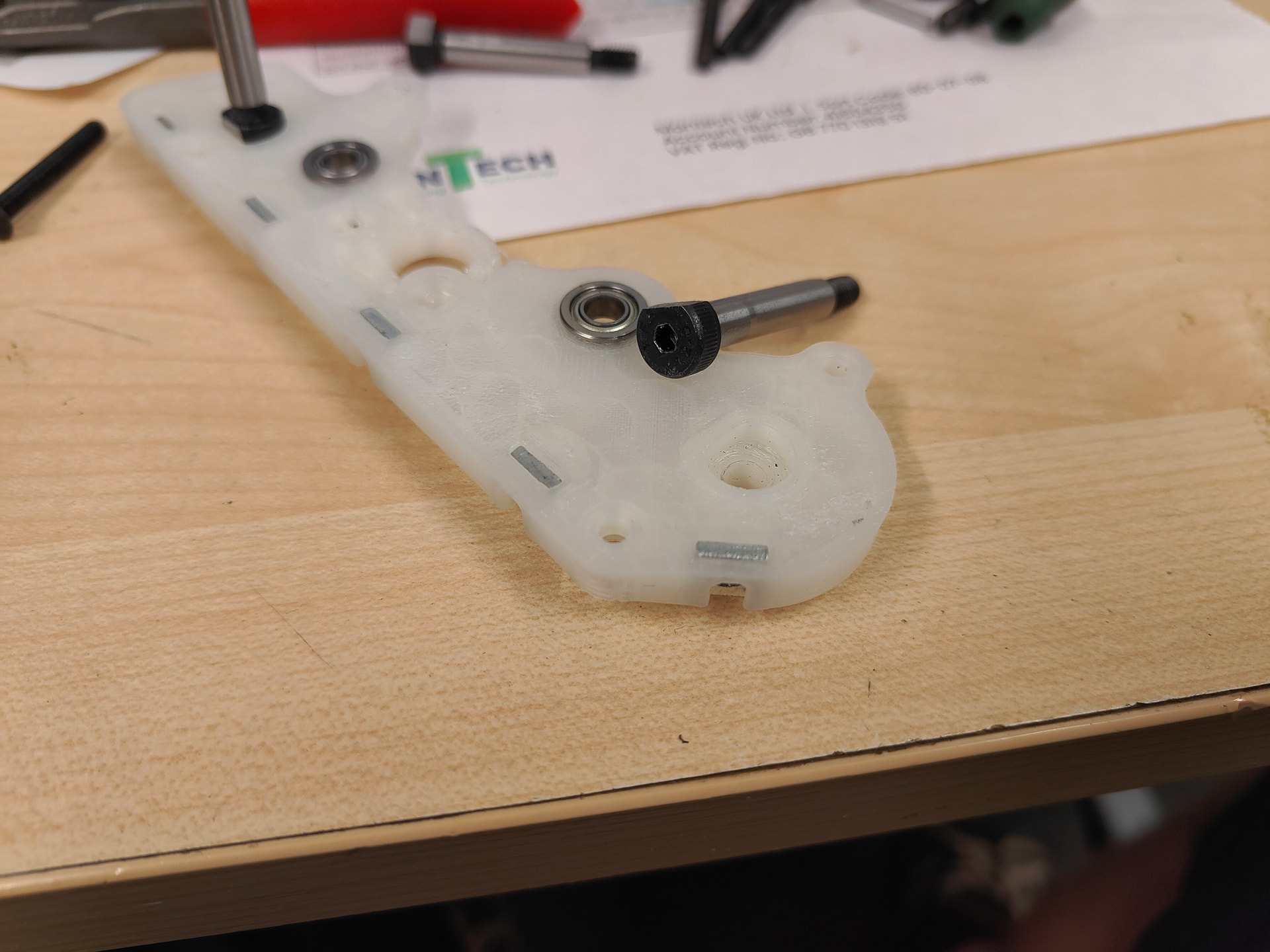
I did some quality of life updates on my drive bulkheads, mostly little geometry tweaking and clearance enbiggening. The main change was small but really mighty. I made the counterbore for the shoulderbolts a ‘D’ profile and filed a corresponding flat on the bolt itself. This just prevents any unwanted rotation and means I don’t have to wrestle an allen key in there to tighten or loosen the wheel nuts.
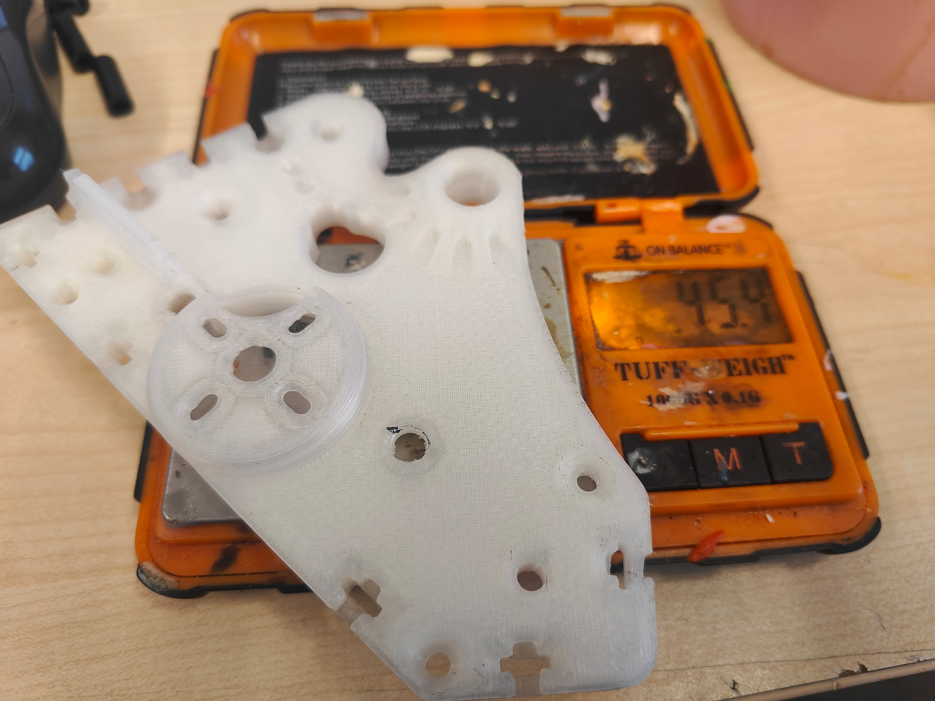
Another excersise in tedium with some before and after skinification.
On the face of it, not a dramatic saving but that panel has all the captive nuts jammed in it and has a much greater wall count. It’s stiffer, stronger and fractionally lighter.
It was then assembly time and I could gop all my bits back together. They are quite a cool little assembly even if it’s not really the best way to approach this sort of robot.
Weight monster strikes again and thus is about 30 grams over what I really want it to be but it’s very workable. One of these things where there’s a lot of effort and quirky solutions to problems that wouldn’t exist if I just used a normal transmission. Hand on heart it would probably be better with just a 22mm brushed setup. Less funny perhaps but better overall.
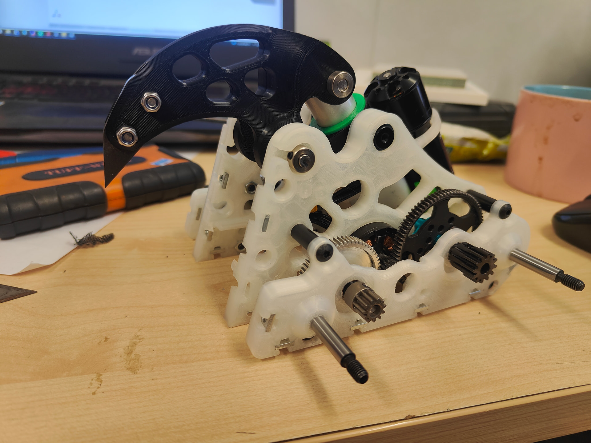
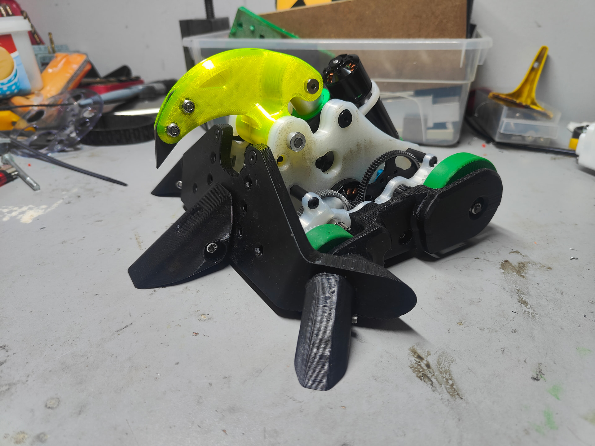
Doing away with the floppy nipper I have changed out for a harder material with some skeletised geometry to get some real stiffness back. This here was a PLA test while the CF nylon dried. I think I’ll have to but the bullet and treat them as consumables because I can’t really find a balance of something that will let me be light enough while also taking an out of plane hit.
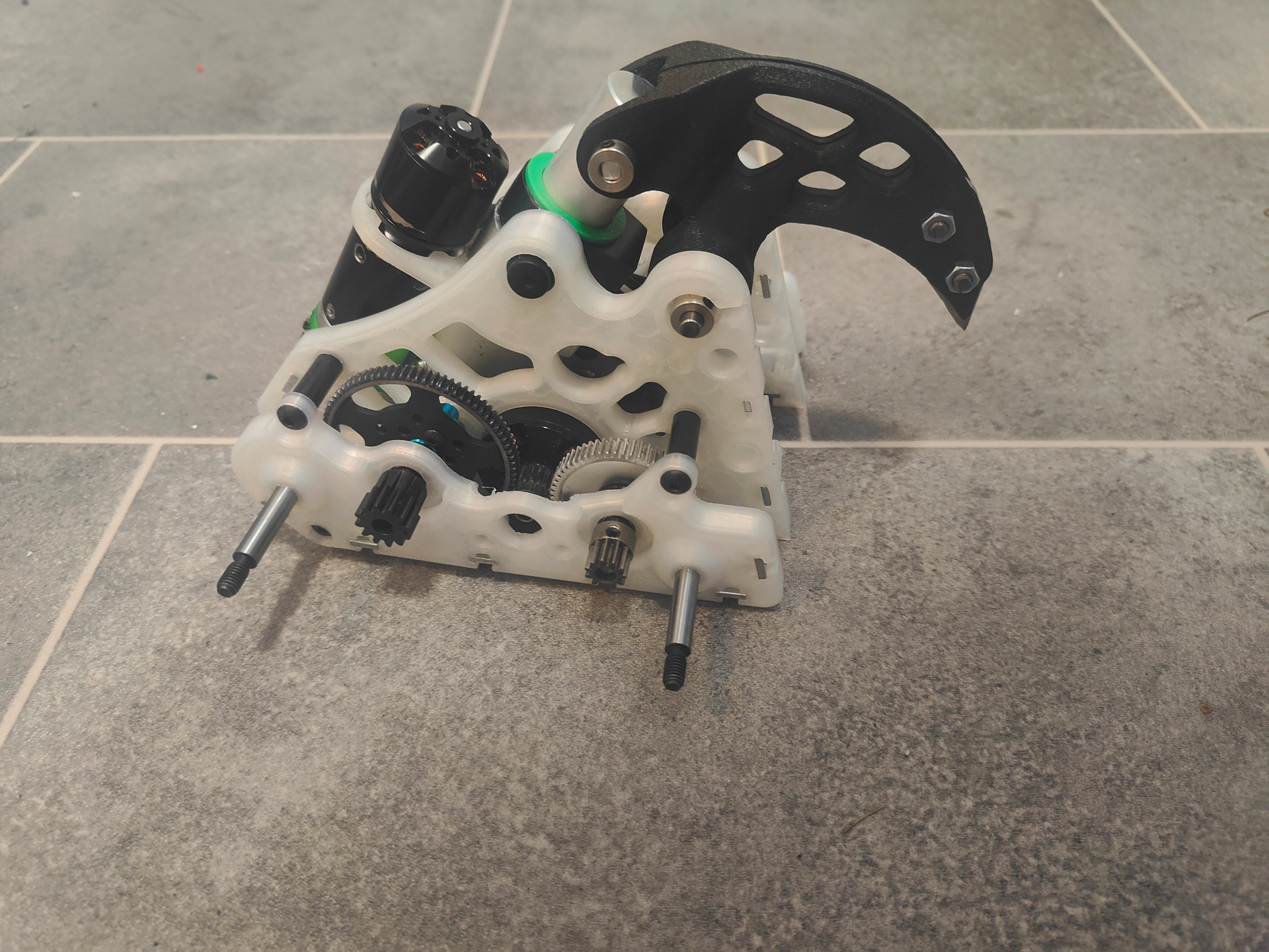
Another shot but this time with the CF jaw. It is phenomenally stiff in the crushing direction and while I have tried to put a bending moment on it with my uncalibrated hands I do feel like it’s going to fail with a hammer blown or human strength.

Now this isn’t particularly impressive on the face of it but I’m now getting a bit of confidence in the scale of this grabbing lark. Soft TPU nibbling and top plate terrorism might actually mean nips has something to do in fights. I seriously lament having to cut reduction in the actuator now but c’est la vie
Excellent news though, I am on the right track! The heaviest single chassis component is now the TPU armour which has had no fiddling and adjusting just yet.
7 Likes
Work of art honestly. The D-ground shoulder bolt heads and corresponding holes is inspired
Kind words Dr Stranglove. Kind words indeed from a titan of Artisto-engineering industry.
Much like dogs take after their owners, robots often end up mimicking their builders. In this case, Fat And Sad. I pressed on with the weight reduction crusade and annexed several key territories - namely the armour.
The geometry was slimmed down and I fiddled with the settings, leaving massive walls and almost no infill. It doesn’t feel as solid but it’s more protected than the last version.
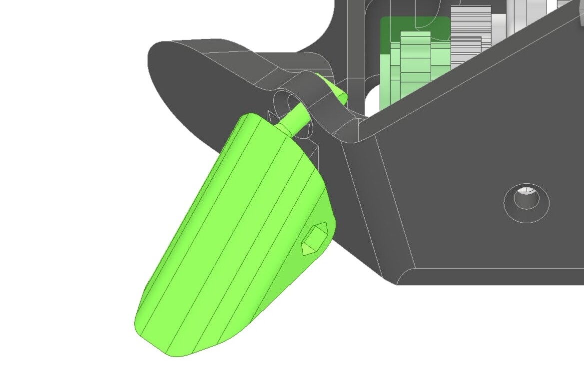
So why am I showing you this little wedgelet? Well eagle eyed readers will have noticed a tiny devastating flaw. Namely when it crushes or when it gets lifted up the wedgelets effortlessly dangle and fold underneath the bot. This doesn’t beach it but it could - if I was unable to reverse etc.
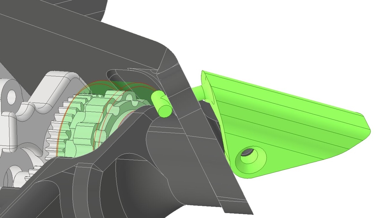
These have the same pivot as before but with the magic compliance of TPU, some ambitious geometry and An Hole I have my own travel stopper.
Same basic premise as these stationery things that people with real jobs in offices who make spreadsheets and smalltalk use. They get folded and jammed through the hole then their wider shape bars then from passing back through. These are on the side flappers and a more hardcore version on the front wedge.
It works better than it has any right to - potentially something like this could be a print-in-place job if I was one of those smart guys with motivation and purpose. Unfortunately I’m a me so I just made it fit by jabbing at it really hard with a pen. My engineering prowess is yet to find a ceiling.

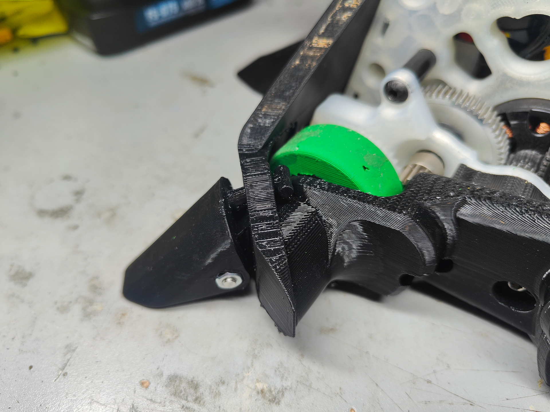
What a beautiful sight. That would bring a tear to my eye if I wasn’t hardened by the nihilistic indifference of modern life. I am going to spend my new found weight based riches on a back pannel to gently cup the actuator and adding in an LED. I’m potentially going to holesaw a clearance hole in the base because I’m getting some rubbing from the spur gear on full retract.
I’m close. So jolly ruddy close.
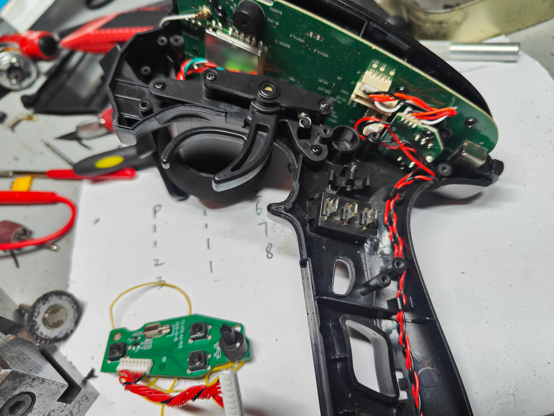
Because I was in danger of finishing a project on time I decided to start mucking around with my only working transmitter and committing electrical hate crimes and brain surgery. I wasn’t a huge fan of how the weapon channel has to be set up on that little toggle.
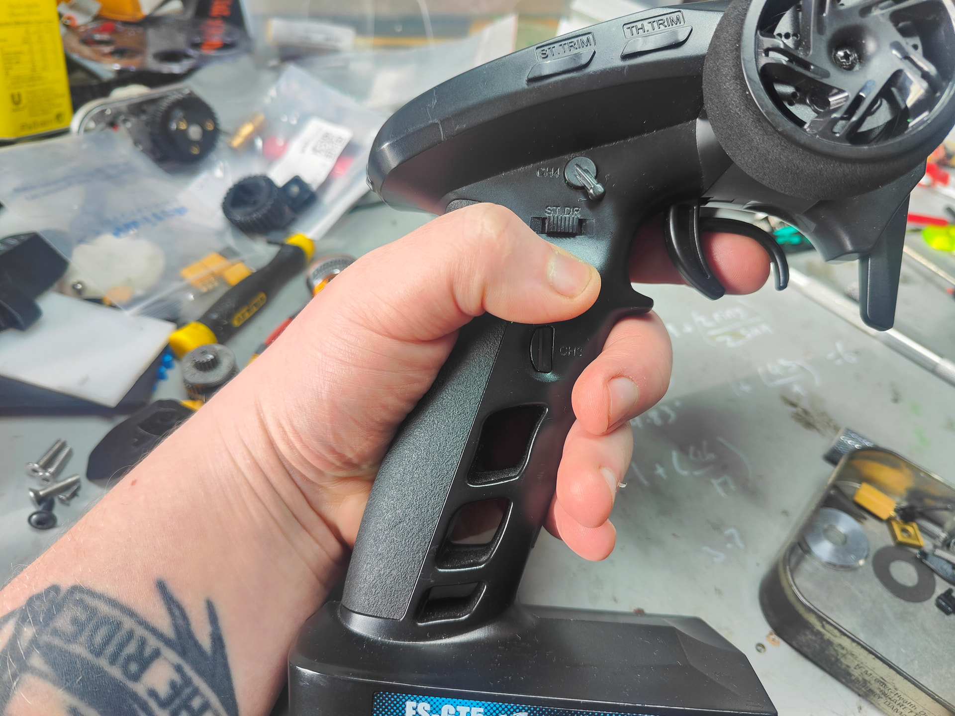
As demonstrated here I have small hands and thick stubby fingers that trigger thoughts of smashed pink richmond sausages. I wanted a 3 position rocker somewhere my mangled excuse for a thumb could reach. I held it and noted where I wanted a switch to go.
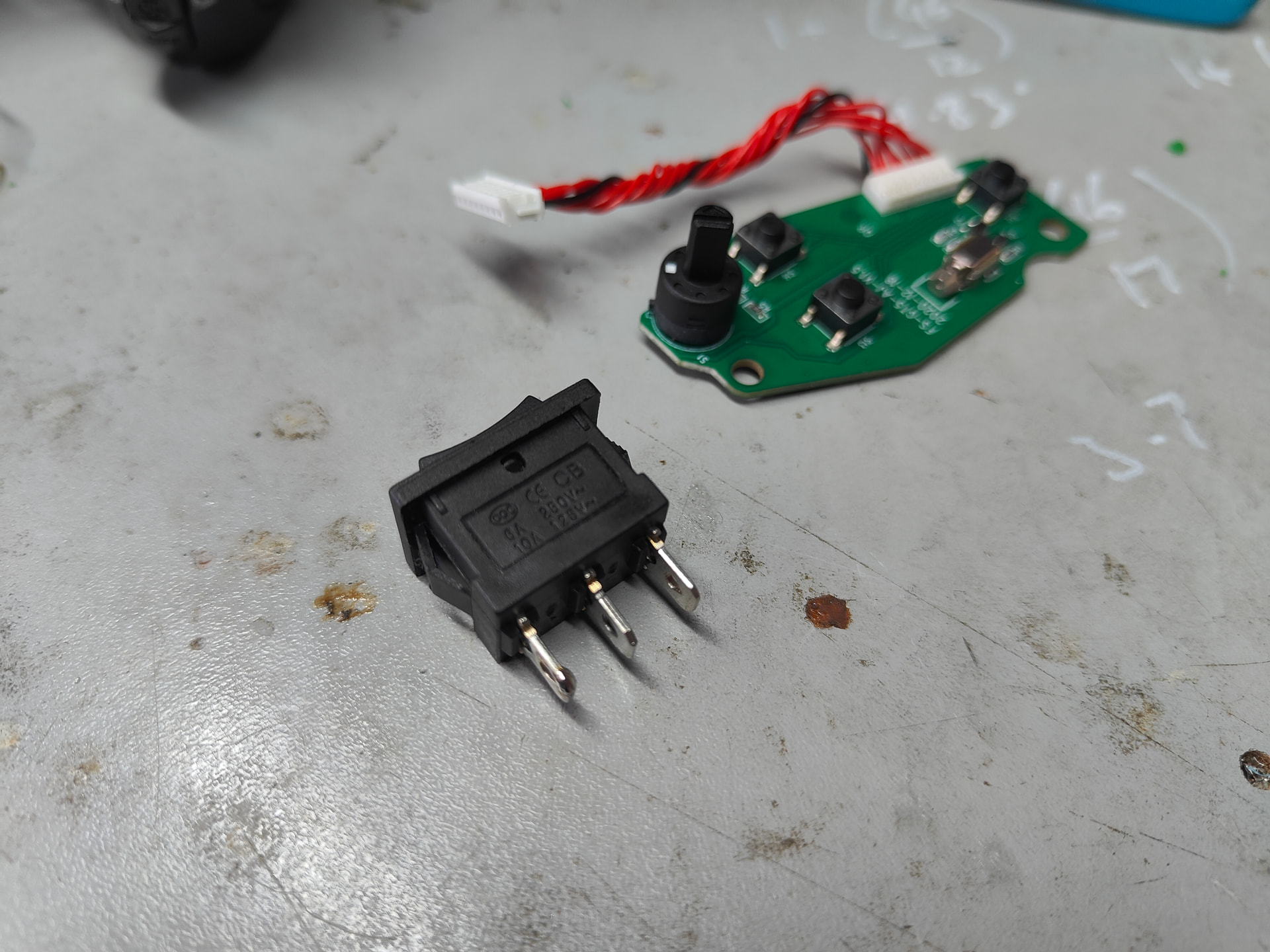
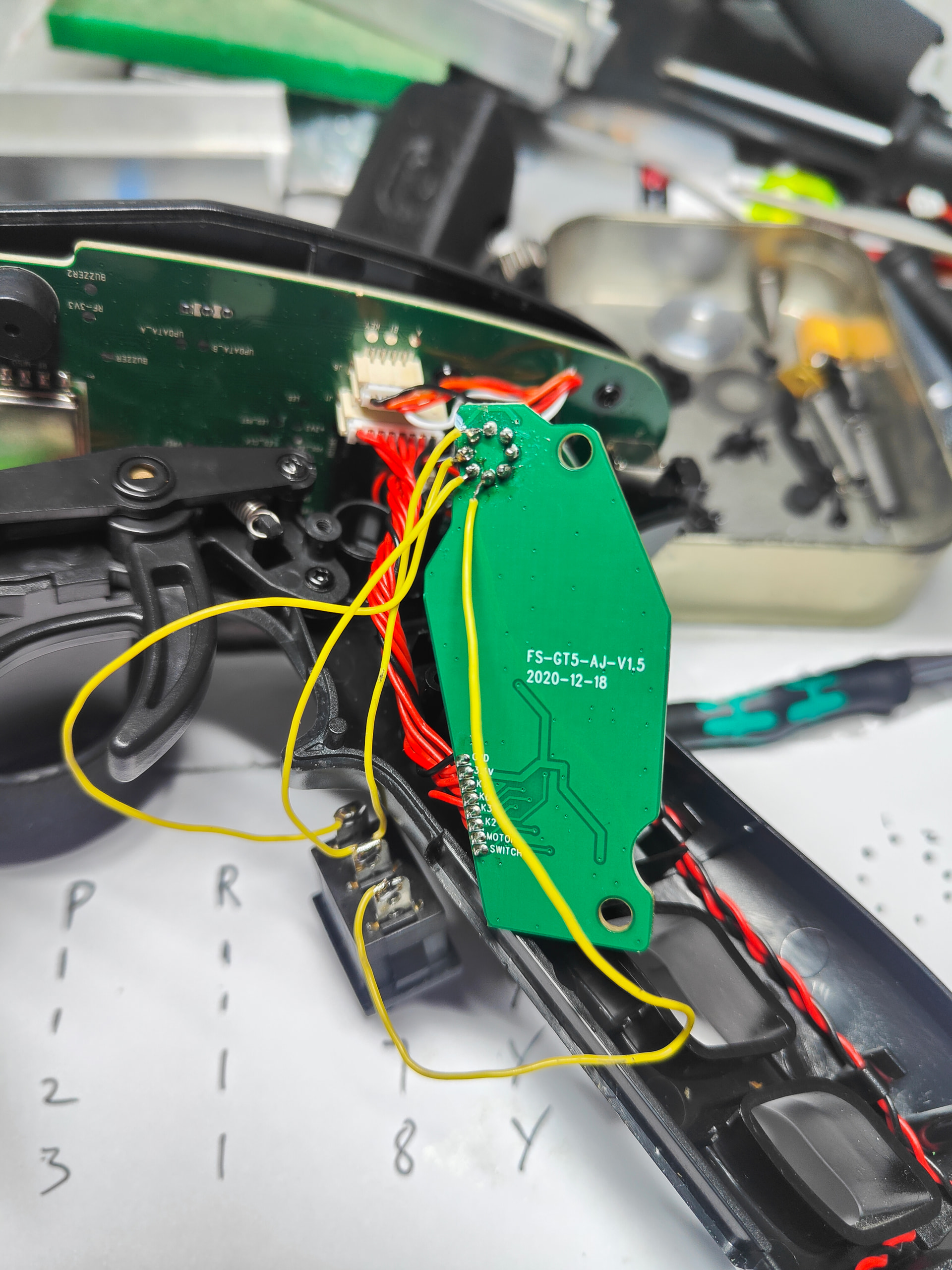
So there’s the main board with it’s strange 8 pin 3 position rotary switch and the ROCKER I wanted to MOD in. Naturally there was conflict - though Yeovil rather than Brighton.
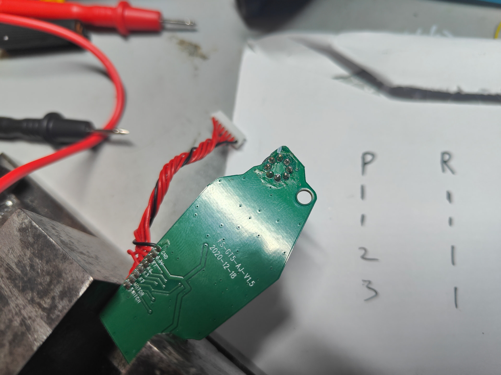
I didn’t have a clue how to jump in the switch but in massive break with tradition I actually found help on Reddit and was able to find switch positions stabbing about with a multimeter
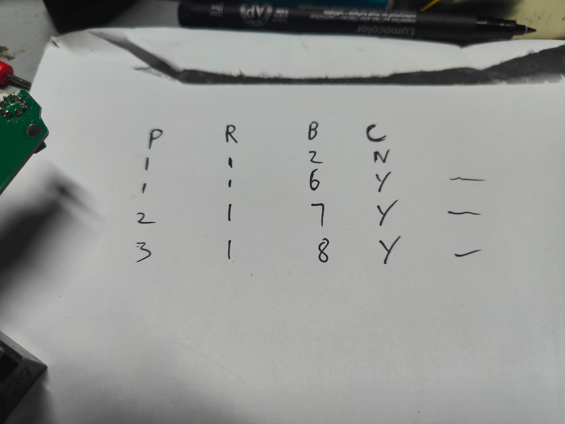
Pin “1” and “7” was my “off” with the rotary switch in the 2nd centre position with 6 and 8 being arbitrary “on” positions. Luckily I didn’t have to be too careful with directions as reversing in TX software is a breeze.
Cut and filed myself out a square slot in the transmitter grip and then hooked it all back up.
I left the wires long as there is the potential for future fiddling and just tucked them in suitable nooks and crannies.
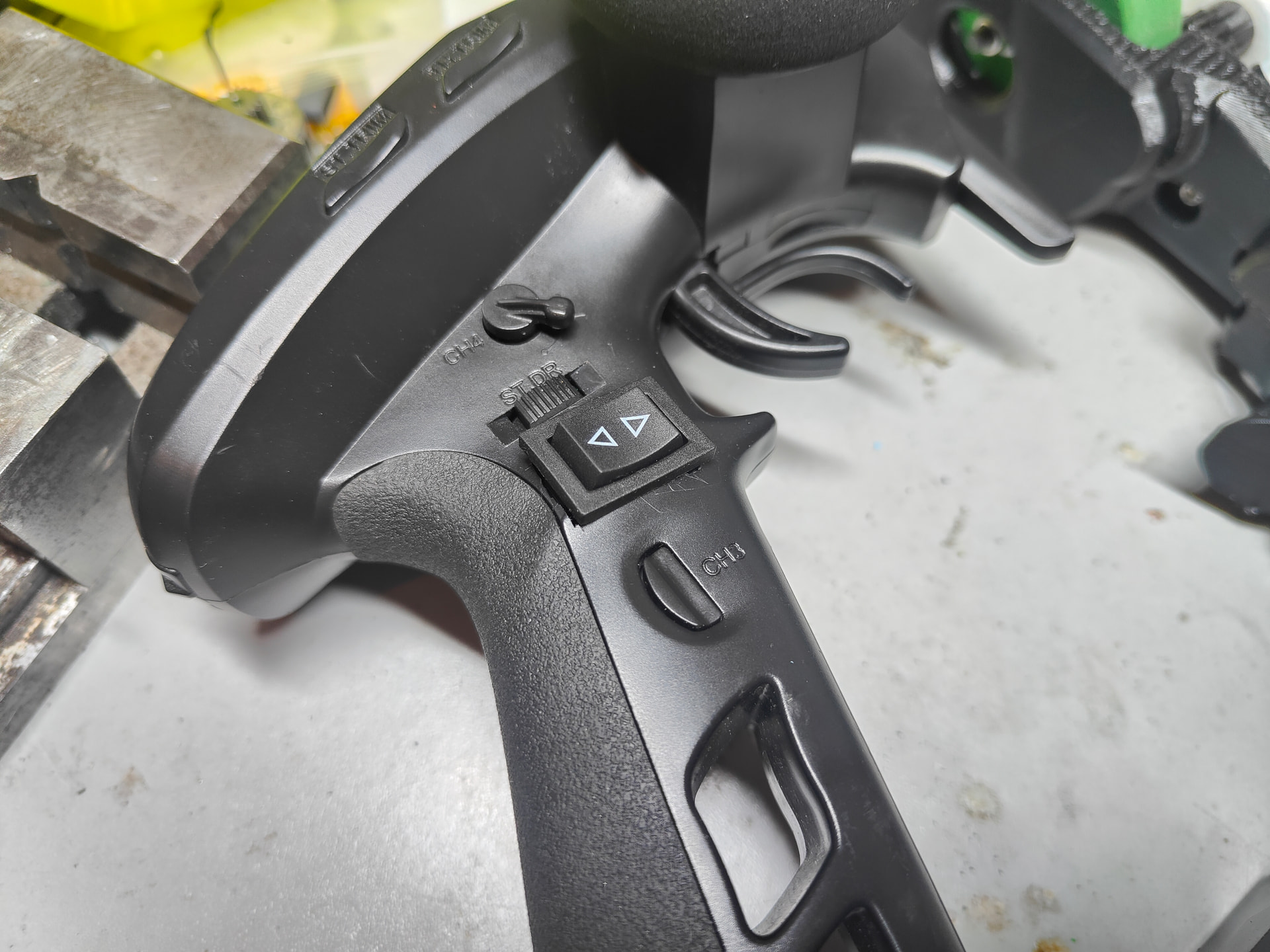
A little our of place due to the curvature of the transmitter and the squarifics of the switch but an odd marriage is often a happy one. It’s very functional and way more comfortable if nothing else.

Works rather well I’d say!
4 Likes