I’m running Mod1 gears on all my bots, and Lego are also Mod1!
they’re definately printable on a 0.5mm Nozzle but I think you’d struggle to go smaller.
Some of us crazy people also use ABS for it’s weight savings, it’a also cheap and relatively tough, but you don’t want to sniff the fumes when printing, and it needs a high temperature print bed.
Hi All,
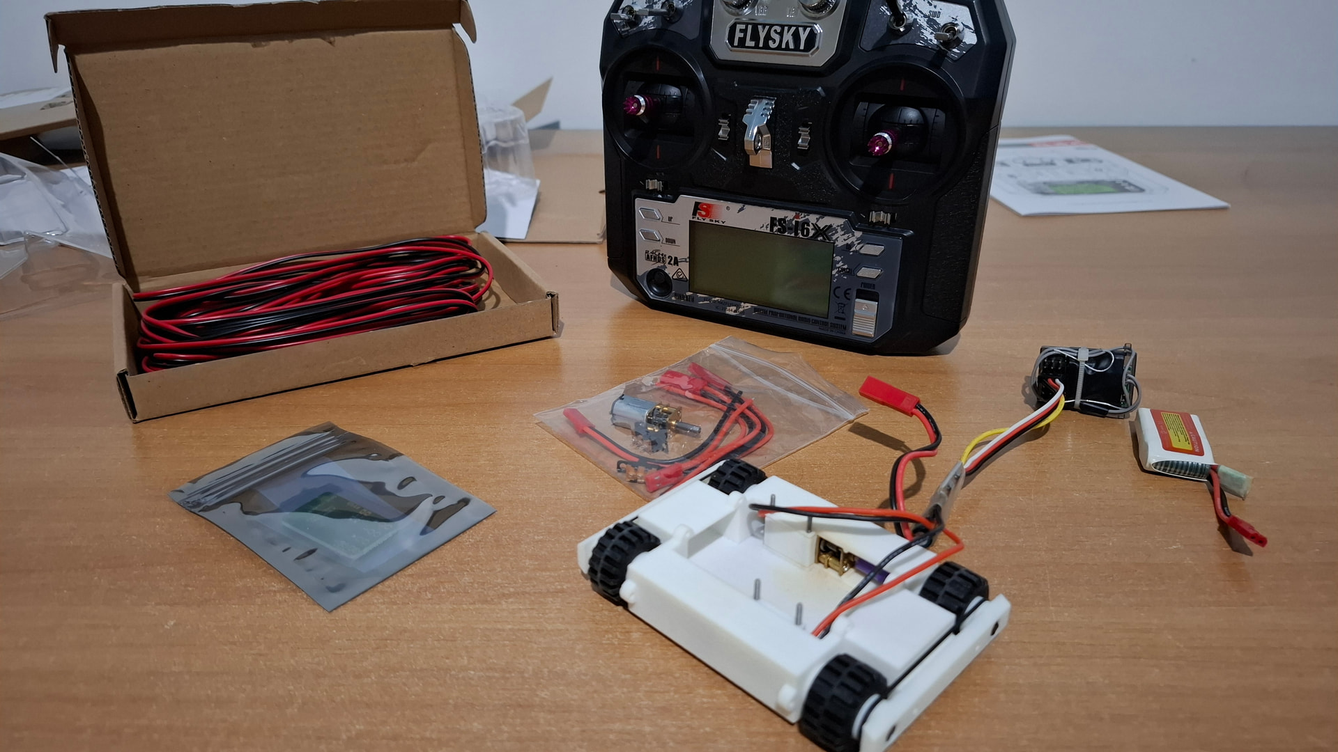
If anyone remembers the original Hydrant, it was a crusher that competed at AWS 62.
The new one follows the same formula: Claw + 4WD + Angled Wedge.
I expect that on almost 100% of uses, the weapon motor will stall and the amps will ramp up. The Malenki Nano says it has 1.8A Max Current.
Electronics is my weakest subject. Does this mean that the Malenki Nano is protected if the motor stalls? The stall current of the motor could be higher. I intend to drive smart and only apply full power if I see there’s a chance of a penetration, but I am worried about frying the speed controller.
Thanks in advance!
provide an image? (both versions)
Taking a look at the malenki schematic it uses TI DRV8837 motor driver ICs. They have built in protection that shuts down the output if it draws more than 1.9A, or if the temperature of the IC exceeds 150C. Because of this the malenki should be safe, but since most N10/N20 motors have a stall current of around 1A you could possibly kill a motor by leaving it powered on and stalled.
Thank you for the guidance. I feel reassured that my design will work, at least for a while.
The new version is still a work in progress, and I don’t really want to turn this into a build diary. Although I will be sure to provide images of the finished product. The original:
Hi All,
I bought a cheap as chips 30rpm gear motor from China.
These are the so called specifications:
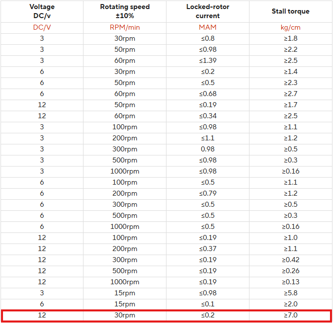
I don’t trust the specs.
Assuming they are accurate, my maths says:
7kg/cm @ 12V = 4.2kg/cm @ 7.2V
Additional leverage due to gearing 1:3.
4.2kg/cm * 3 = 12.6kg/cm
Crusher tip @ 75mm distance from axis of rotation.
12.6kg/cm / 7.5cm = 1.68kg === 16.5 N
Could someone please tell me if this makes sense?
I think a problem with the previous version of Hydrant was that the gearing involved a worm gear, possibly losing 50% efficiency, so it didn’t live up to it’s billed potential.
Steven
sounds right but mind that the 30rpm one are the 298:1 n20 that loves to self destruct when stall, you better use some lower reduction ones and try to increase the 1:3 stage reduction where you can use bigger module gears to hold the power
it also depends if you want a good grabber or a crusher, less than 20N tip force sounds more like a grabber, for a pure crusher i would aim around 100N minimum and 500N could do good damage (and danger)
Point taken.
I’ve got a couple of motor options so hopefully I can find a good balance.
I suppose all crushers are grabbers, but not all grabbers are crushers.
Hi all,
I’m looking for some advice regarding two battery options for my Hydrant build.
I currently have:
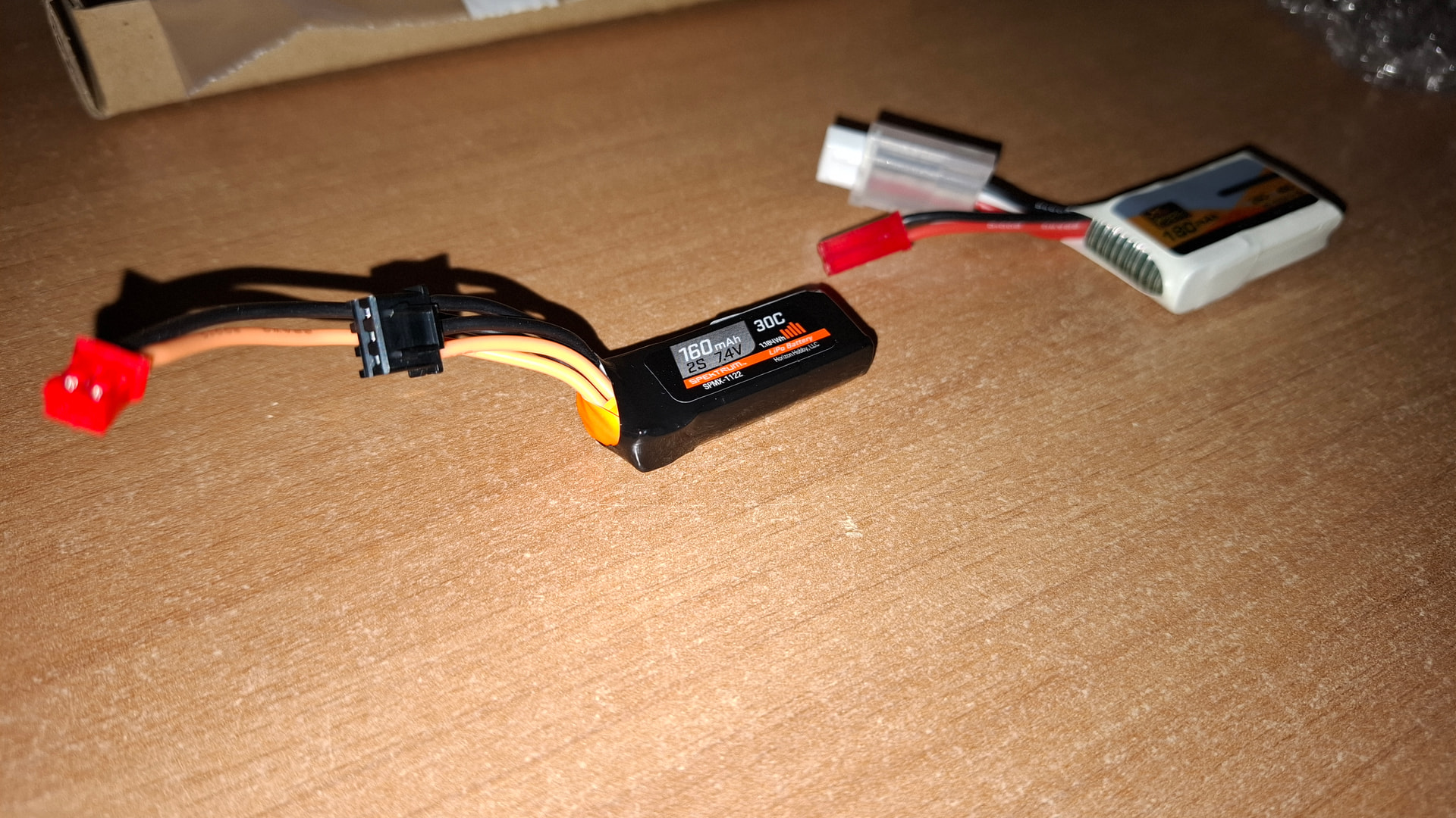
180mAh battery (right) - fitted with a standard JST connector and an additional connector that I’m not familiar with.
160mAh battery (left) - fitted with a JST-PH connector and another connector that I’m also unsure about.
My goal is to:
Replace the JST-PH connector on the 160mAh battery with a standard JST connector, so it’s compatible with BBB connectors.
Either safely insulate or completely remove the secondary connector on the batteries, as I have no use for it and it takes up unnecessary space.
Could someone advise on:
- The correct connector type and components I would need?
- The safest and neatest technique for carrying out the swap?
- Recommended methods for insulating or terminating the unused connector?
- (If possible) links to suitable connectors or insulating plugs?
Thanks in advance for your help.
Steven
On the left you’ve got a JST-XH balance plug and (I think) a JST-PH power connector. I can’t tell what the balance plug is on the right, but it’s probably another JST-XH. The power connector on the right is a JST-RCY.
When you say “replace the JST-PH with a standard JST connector”, do you mean replace it with a JST-RCY? It sounds like you also want to remove the balance connectors entirely, which is a really bad idea - if the cells go out of balance you’re likely to over-discharge one and then over-charge the other, which is how you speedrun a pit table lipo fire.
Instead, if you’re short on space I’d recommend removing the power connectors and instead using the balance connectors for power. I assemble my own batteries from bare cells, and I just use a single JST-XH with the shortest wires possible on all my batteries:
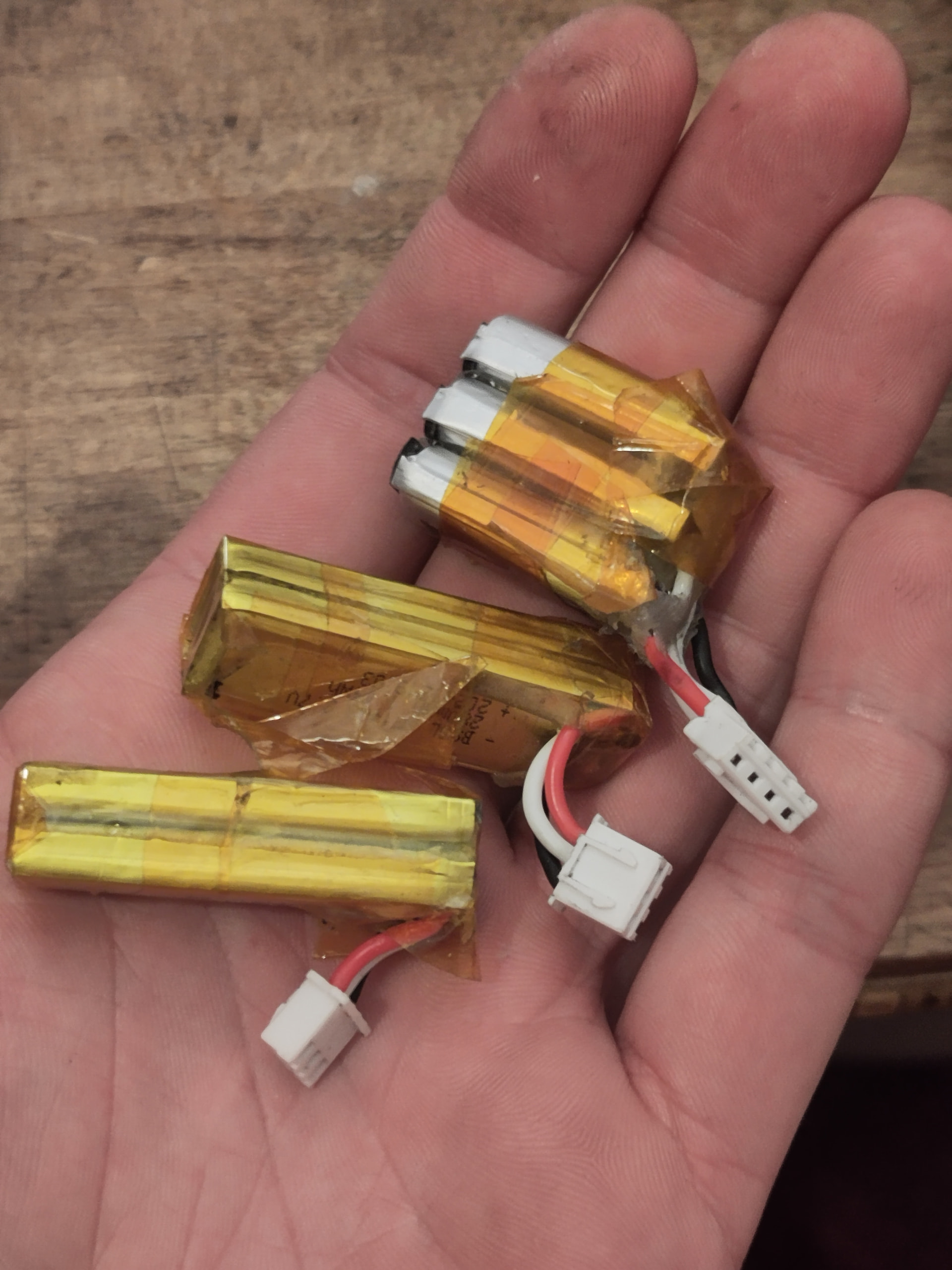
While it’s a bit bulkier than the RCY you can still balance charge, and although the JST-XH is only rated to 3A I’ve pulled 10A through mine with very little voltage drop and absolutely no melting.
To terminate the main power wires I would cut one wire down to about 10-15mm length, and then use either some glue-lined heatshrink or a blob of superglue and some regular heatshrink to cover the end of the wire. Repeat with the other wire, then you can tape the wires against the pack with kapton tape (preferable) or electrical tape (gross and sticky but acceptable).
I hope I got the right end of the stick there, and I hope my reply was helpful! I’ve built a good few custom batteries (mostly from discarded vapes I find in gutters and hedges) and only one or two have gone out the window trailing smoke.
Also, always good to see another antweight crusher!
Thank you for responding. This is about getting the electronics right of course! I know I’m not experienced.
Hi All,
Apologies for another question, but I’m looking ahead to Hydrant v3 (possibly a year or more from now) and want to think through a potential performance improvement.
I’ve identified a motor/gearbox combo for the claw that appears stronger and provides more torque. Ideally, I’d like to implement this without needing to 3D print all the parts again, so I’m focusing on a redesign of the chassis to accommodate it.
The challenge is that the motor/gearbox can only fit in one orientation. To maintain proper alignment with the current external LEGO-based gears, the mesh point would need to be 4 mm away. However, at this position, there is a 0.25 mm interference with another piece of existing geometry. Ideally, I would like at least 0.1 mm clearance there.
If I offset the motor/gearbox by 0.35 mm (0.1 mm + 0.25 mm) — i.e., 4.35 mm from the mesh point — the gears would start to lose proper mesh. Given that LEGO gears have a large tooth addenda, I’m wondering if scaling the gear by roughly (0.35 / 4 × 100) % would resolve the interference without causing mesh issues.
Is this feasible, or would it introduce significant problems? Alternatively, I could consider machining the gearbox casing to create the necessary clearance.
Any advice or thoughts would be greatly appreciated.
All the best,
Steven
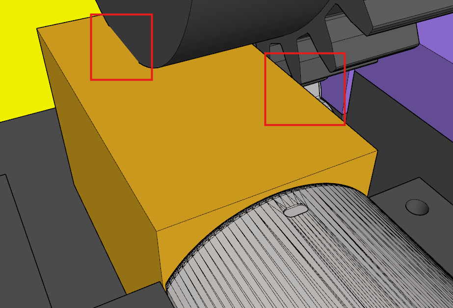
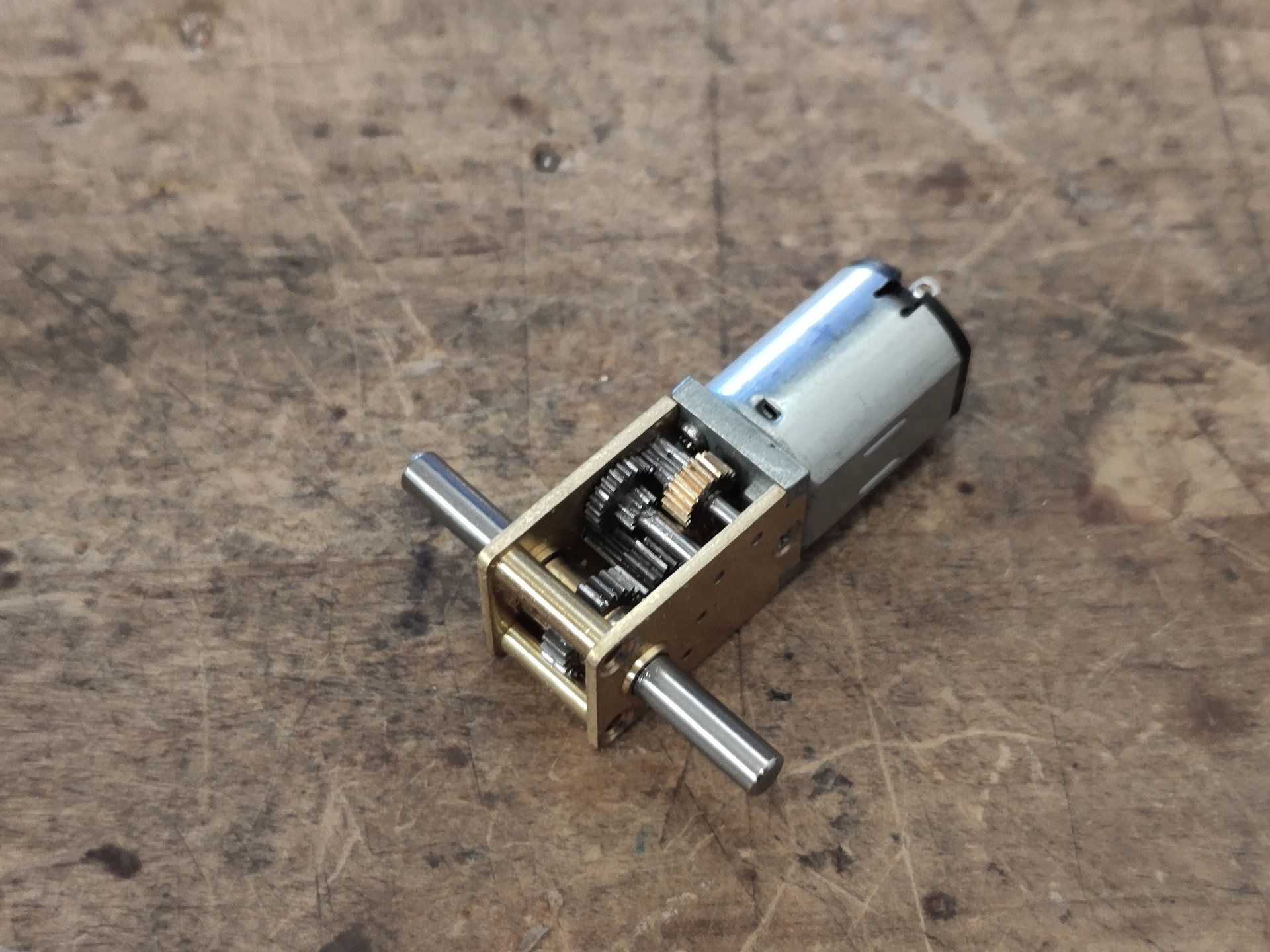
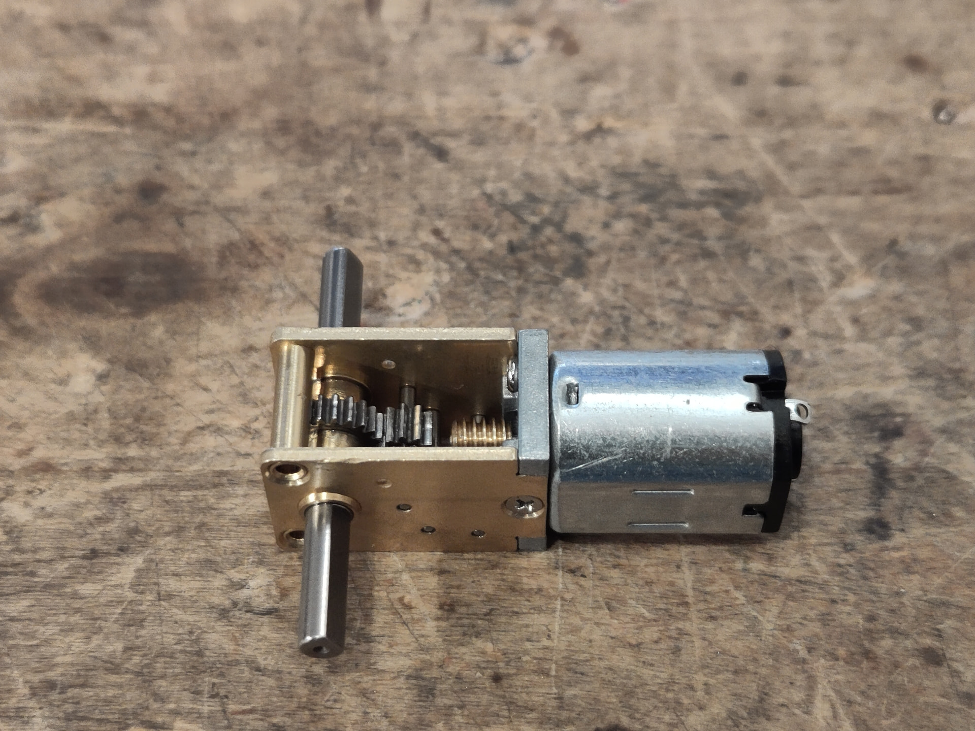
Is that one of these little N20 right angle jobbers? At least on the one in my junk box it looks to me like there’s plenty of space to file the housing down for clearance. Otherwise I would probably just tweak the ratios slightly - it might be easier to add a tooth and maintain the module rather than scale the whole gear.
Thank you for the high quality picture and advice. That’s exactly what I wanted to hear!
1 Like
Hi all,
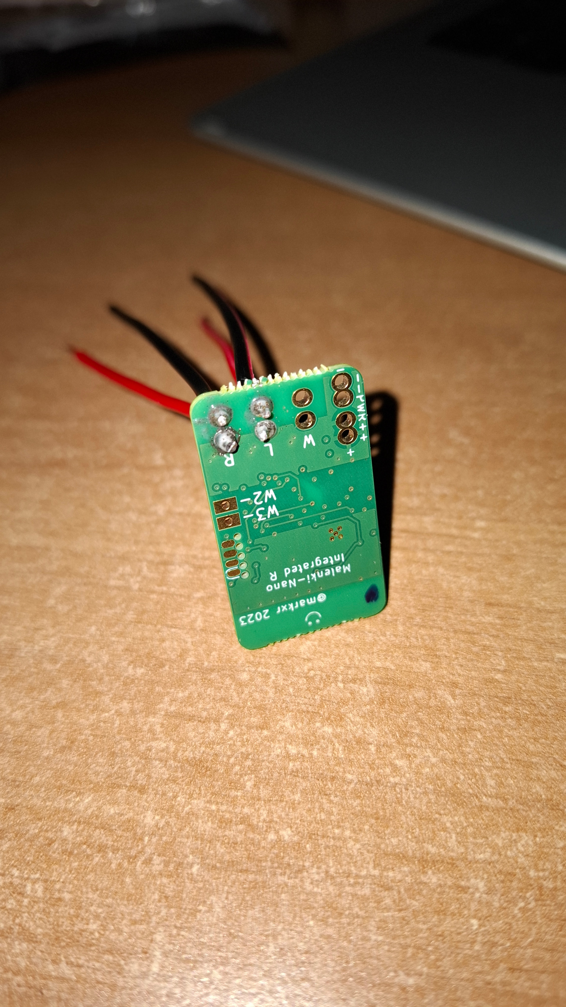
Could someone please rate the soldering job on this malenki nano? Do I need to redo it?
I have a medical condition which makes my hands shake.
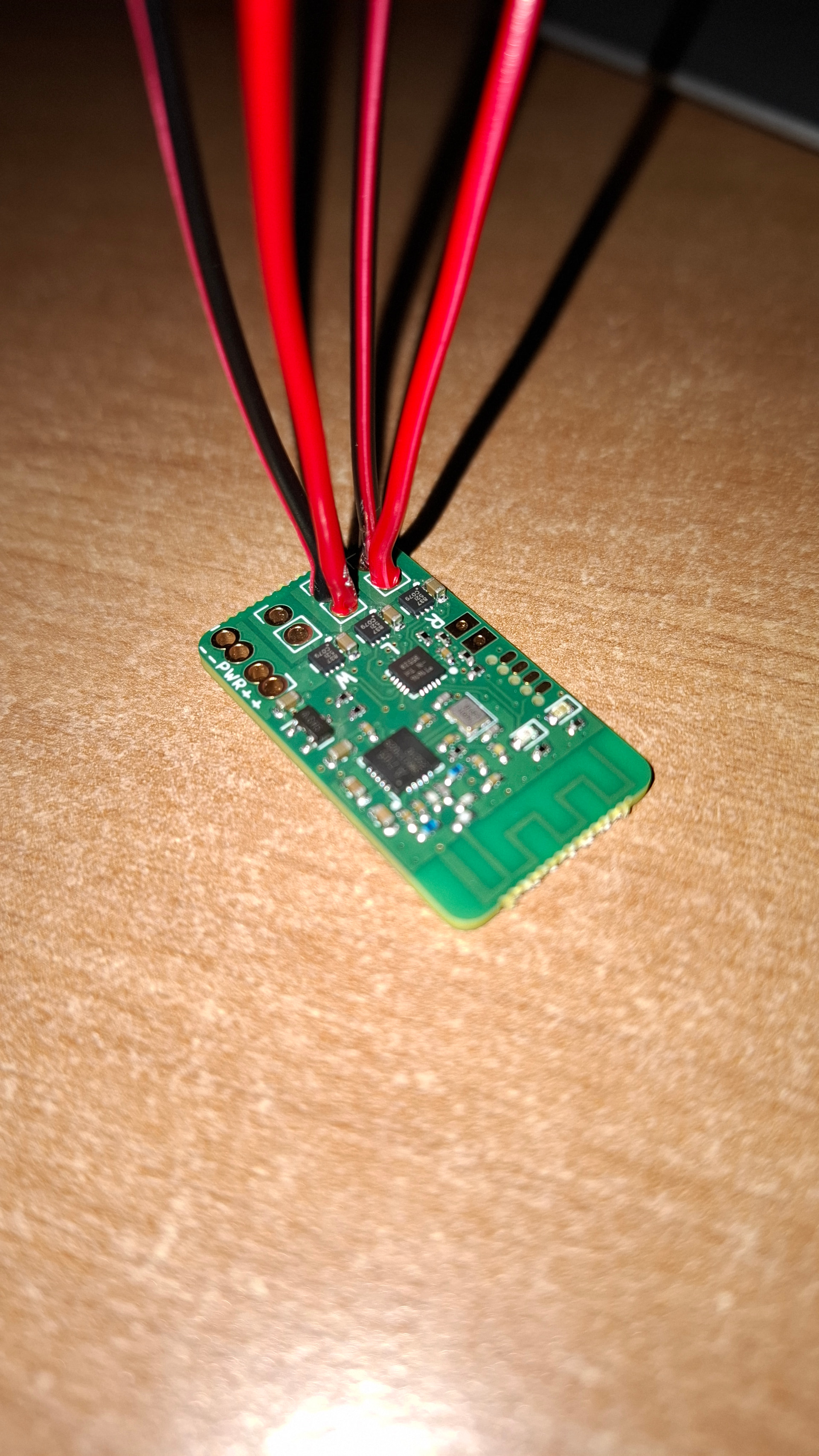
Thanks in advance,
Steven
The joints do look a little suspect. They should be smooth and shiny. Before you start, make sure the tip of your iron is clean. There are special sponges for this or you can use a wire wool type tip cleaner. At a push, a bit of damp kitchen towel will do the job. Apply a little fresh solder to the iron before you start. It is best to tin the wires by melting the solder into the wires first before inserting into the hole (assuming they will fit). Place the soldering iron so it heats the wire and the board together. Apply the solder to the joint then remove the solder and iron as soon as the solder starts to flow. With a small board it is a good idea to have something to hold it in place, so you are not chasing it around the bench. Old fashioned tin-lead solder is easier to use than the modern stuff.
Thank you very much. That’s very helpful! I don’t have much tooling, but I can certainly improve my technique and clean the soldering iron.