A while back I was thinking about a better way to gear down the lifter in the FW version of Perillelogram, without faffing around with all the bits that go into a hypocycloidal gear. I have also been playing around with supposed “robots” at work that are just these lame arm things, but this brought me back to thinking about Harmonic Drives™, or more generically (but less aestheically), strain wave gears.
I have watched a few videos about 3D printing these in the past, and they all seemed to fall over because they rely on flexibility, which 3D printed filaments suck at. Cycloidal always wins. Except…
[record scratch]
…3D printed filaments don’t suck at flexibility if they’re TPU. Which most robot builders use a lot, even for gears and such, so I decided this was worth a try.
Although the initial thought was sparked by the need for better lifter gearing, I actually felt a more pressing application was the drive for Captain Kathryn Chainway. Originally she ran drill motors at 4s, for a 4wd slightly-undwerweight feather, resulting in a burned out motor roughly every other fight. Upgrading to 37T 550 RC car motors improved this to about a motor per event (5 fights, give or take), but this is still short of an optimal level of reliability and at least in part due to me driving more cautiously. So, I needed more drive power, but I didn’t really want more motors, and wasn’t emotionally ready to go brushless, which meant just BIG BRUSHED. But! This still needs BIG PLANETARY GEARBOX to slow down, which means WEIGHTY. Perhaps 3D printed strain wave gears were the answer…?
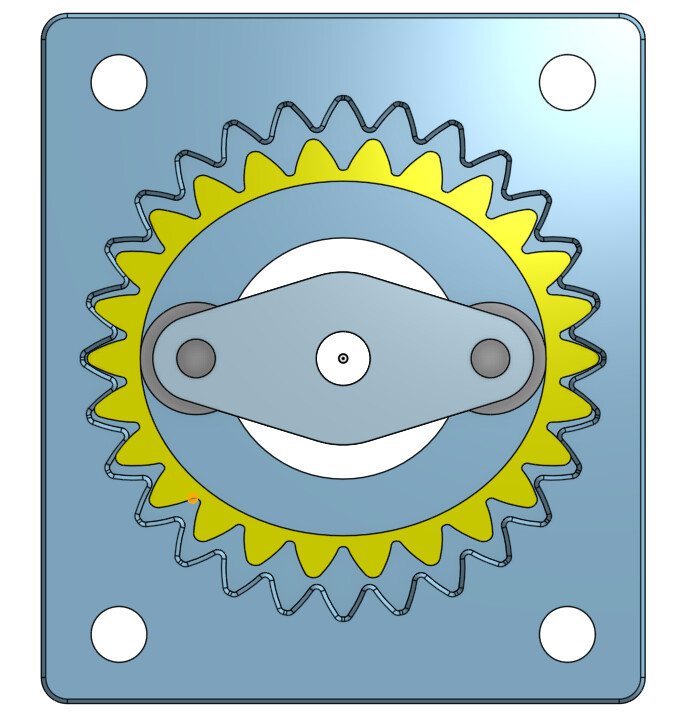
I started out designing a test model, just to play around with, and sized to fit in Captain Chainway. The basic idea with a strain wave is to have an rigid, fixed outer ring gear, with a flexible inner gear that is the same tooth profile but has slightly fewer teeth (left). You then distort the inner gear to mesh with the outer gear (right).
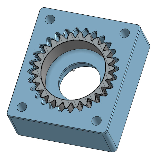
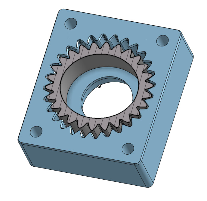
The clever part (one of the clever parts) is adding a “wave generator”, which then moves the point(s) of contact around. This causes the flexible gear to rotate in the opposite direction, at a rate that is slower than the wave generator in proportion to the difference in the number of teeth, dibided by the number of teeth on the inner gear (BREATHE). In this case, I have tried mod 2mm, with 28T outer and 26T inner, giving 13:1
The next clever(ish) part is getting the teeth to mesh in a reasonable way while they’re squishing and stretching all over the place. The tooth profile is thus pretty non-standard, with a 30° pressure angle and very rounded ends. Otherwise, the teeth interfere as they flex away from each other.
To get the squishy-rotation somewhere useful, you need a section of material that gradually transitions from elliptical flexing to circular. This was my attempt at that:
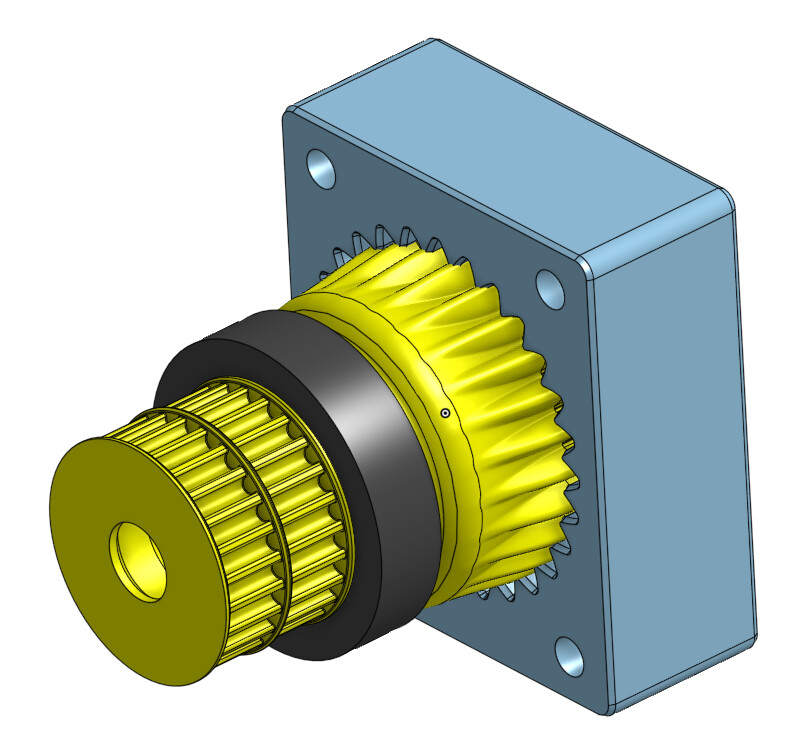
You can see I’m getting carried away here and designing pulleys and such onto this. There is also space for a big outer bearing (40mm bore) and potentially a smaller 19mm OD one inside.
The final part to add is the wave generator itself, the thing that makes the whole thing flex:
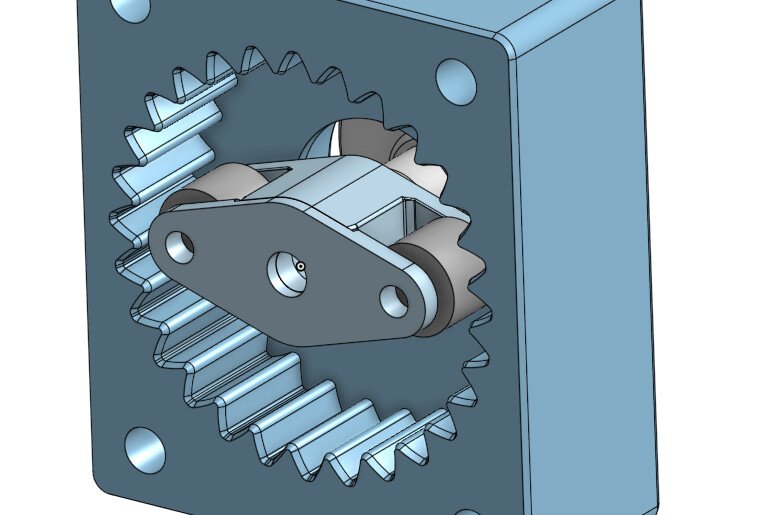
Some pre-existing 4mm bearings make contact with the inside of the flexible gear.
Time to HIT PRINT:
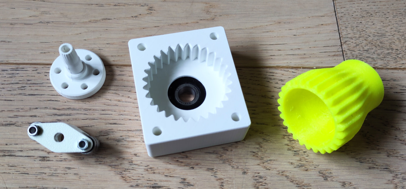

Note presence of a) roundy-roundy and b) less roundy-roundy in the other direction
This just about worked, buut was very stiff. I wasn’t sure if this was because the print was crappy (I just got a new printer, woooo, but hadn’t quite got the hang of the Orca interface and forgot to turn on the wall-avoiding thing so it was full of bogies) or there was still some interference.
I printed out some test pieces with better quality and extra clearance inside and out. The original geometry was fine with tidier inside surfaces:

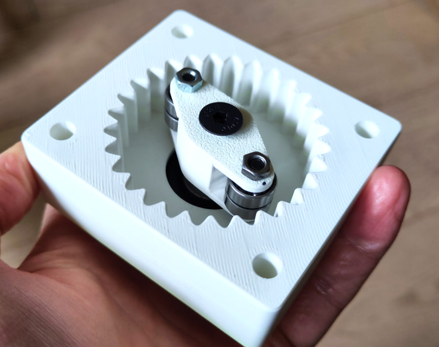
So I printed a whole test piece out:

It works! Provisional evil laughter.
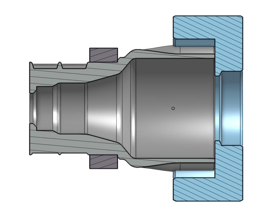
What’s (retrospectively) unsurprising is that there is still quite a bit of taper, i.e., a difference in circularity, through the thickness of the engaged parts here. This means thatt the pressure from the wave generator is applied over a small area, and that the teeth are not engaged through the full thickness. There are two ways to fix this, that I can see…
- Make the flexing part longer (axially) and/or the preferably not flexing bit shorter.
- Change the cross section along the axis of the inner/outer parts so that they fit together nicely when in position.
Currently leaning towards option 2, with a soupçon of option 1, but currently trying to get ready for BEVs next weekend and I’'ve just dropped an important bolt on the floor and lost it so hopefully more updates in a couple of weeks, but right now g2g, must find bolt. TTFN.