Harry's Beetles

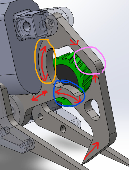
Right so that’s on the docket for ML-T34. Almost certainly will have one on the retract but I’m not sure getting an end stop on the forward swing is entirely possible or appropriate with things the way they are. When I design an axe from the ground up that will absolutely be a consideration from day dot.

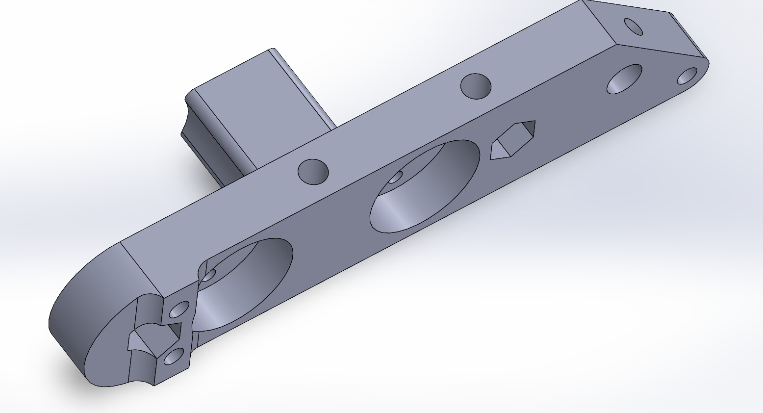
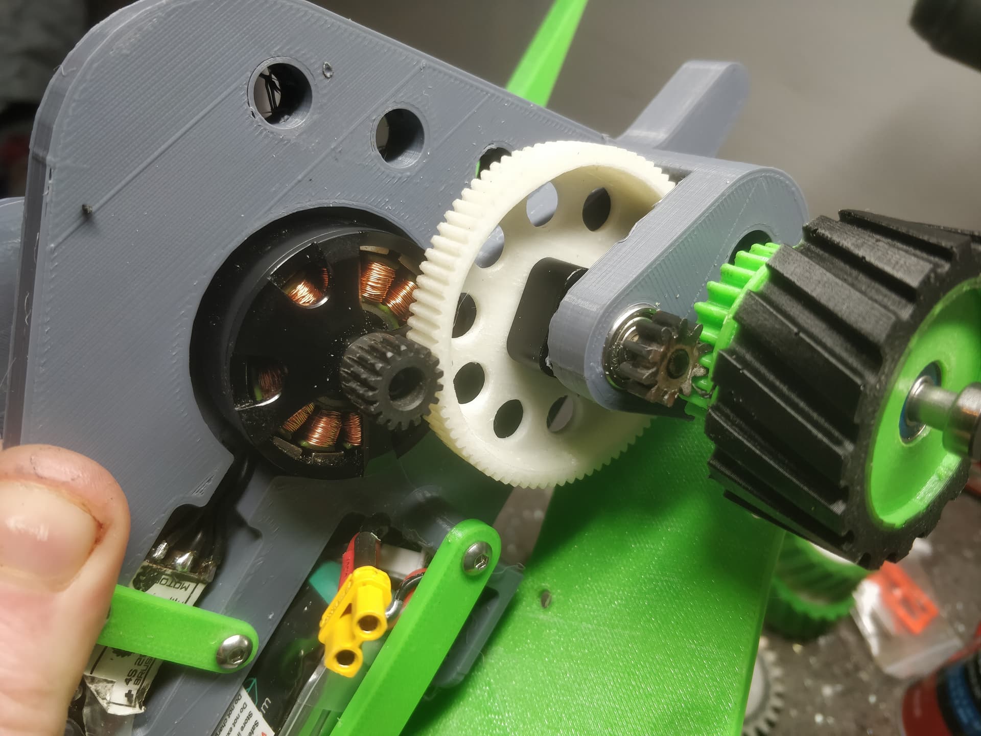
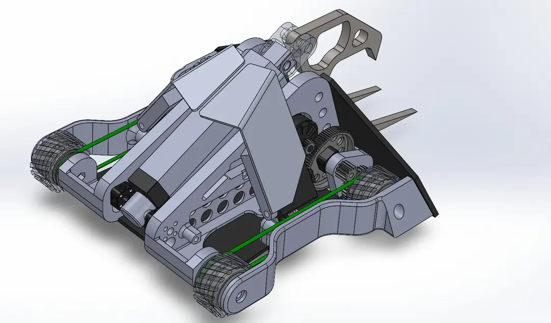
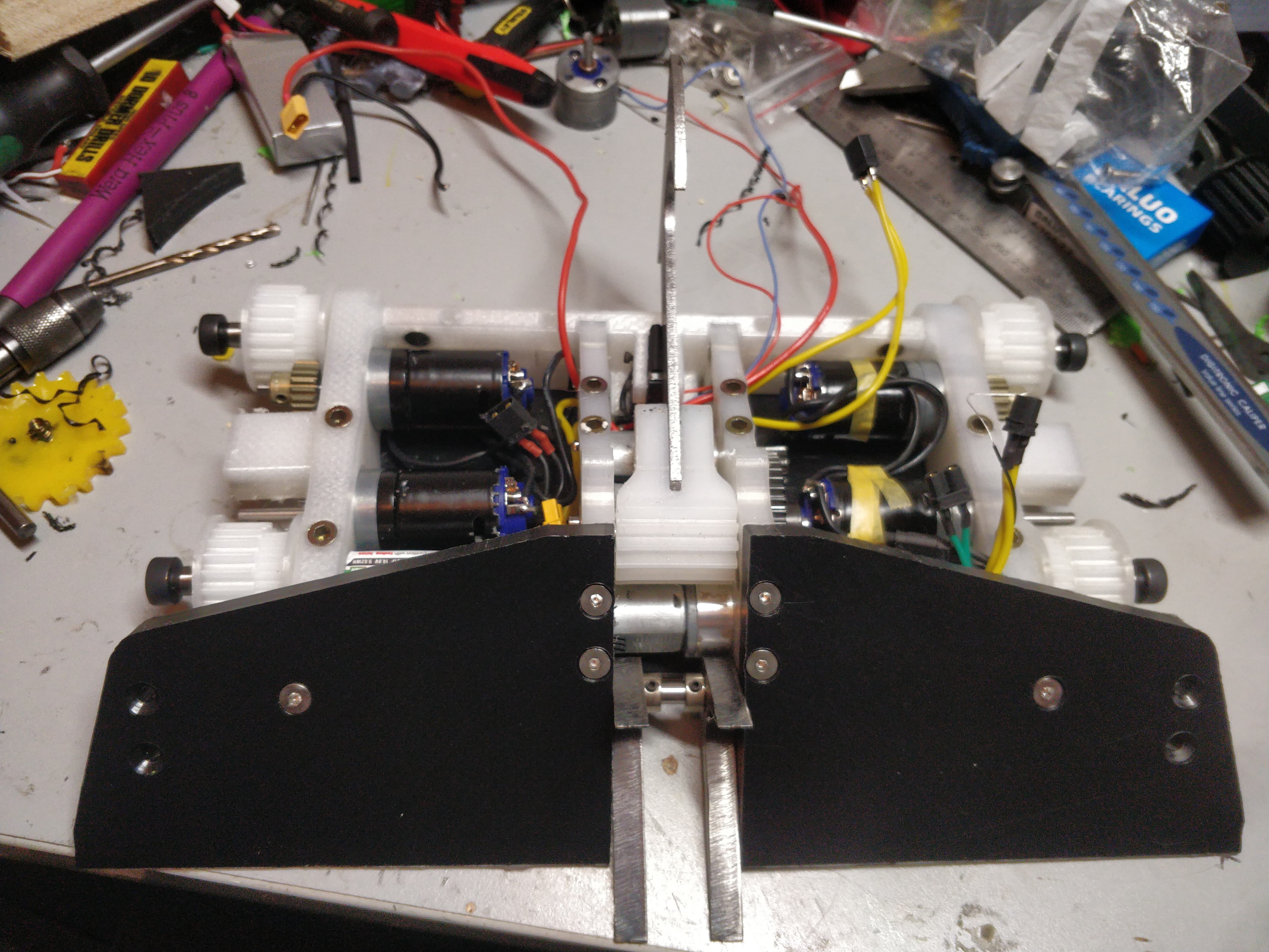
I have another bulkhead to reprint as I had to tweak things slightly to push the width out by a further 6mm so one of the drive motors just clears the boss on the 40t motor spur gear. You may revel in the frighteningly banal nature of the CAD model.

Over Christmas and new years I am going to try and get some more tracks printed, cast and a get a robot driving and chopping with the best of them. From there the aim is going to be to buy the battery I’ve had my eye on and start making templates for HDPE armour.

I put robot stuff loosely to the side for a week as I was in Amsterdam for an end of year jolly. Relevant to this is it ended on a bit of a bum note being stuck for an extra 6-7 hours in Schiphol airport due to reports of Extreme Gustiness. This gave me unfiltered access to several bars, a lot of coffee and Time To Kill.

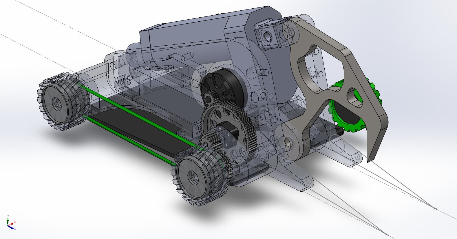
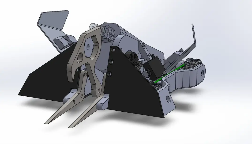
Here is the end result of rattling around in my head unimpeded. It is also a rare glimpse into just how the sausage is made with my awful design discipline. I tend to rack up a bunch of solid blobs into an assembly then just go hard and fast sketching and scribbling all up on them. Morphing them on the fly to get the shape right. I’m always really milquetoast with my designs as they tend to just be boxes dressed up with an angle or two. I am trying to make this a departure from that - semi successful.

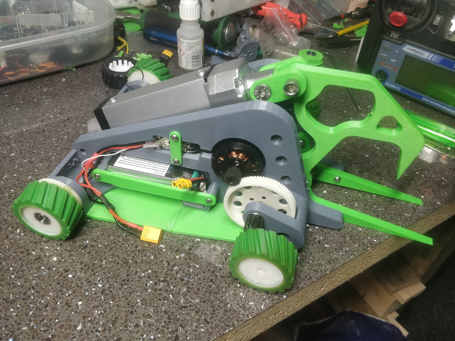
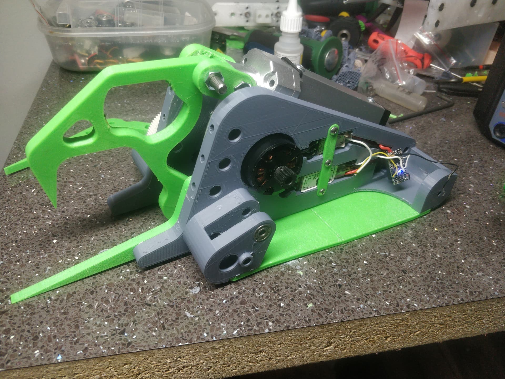
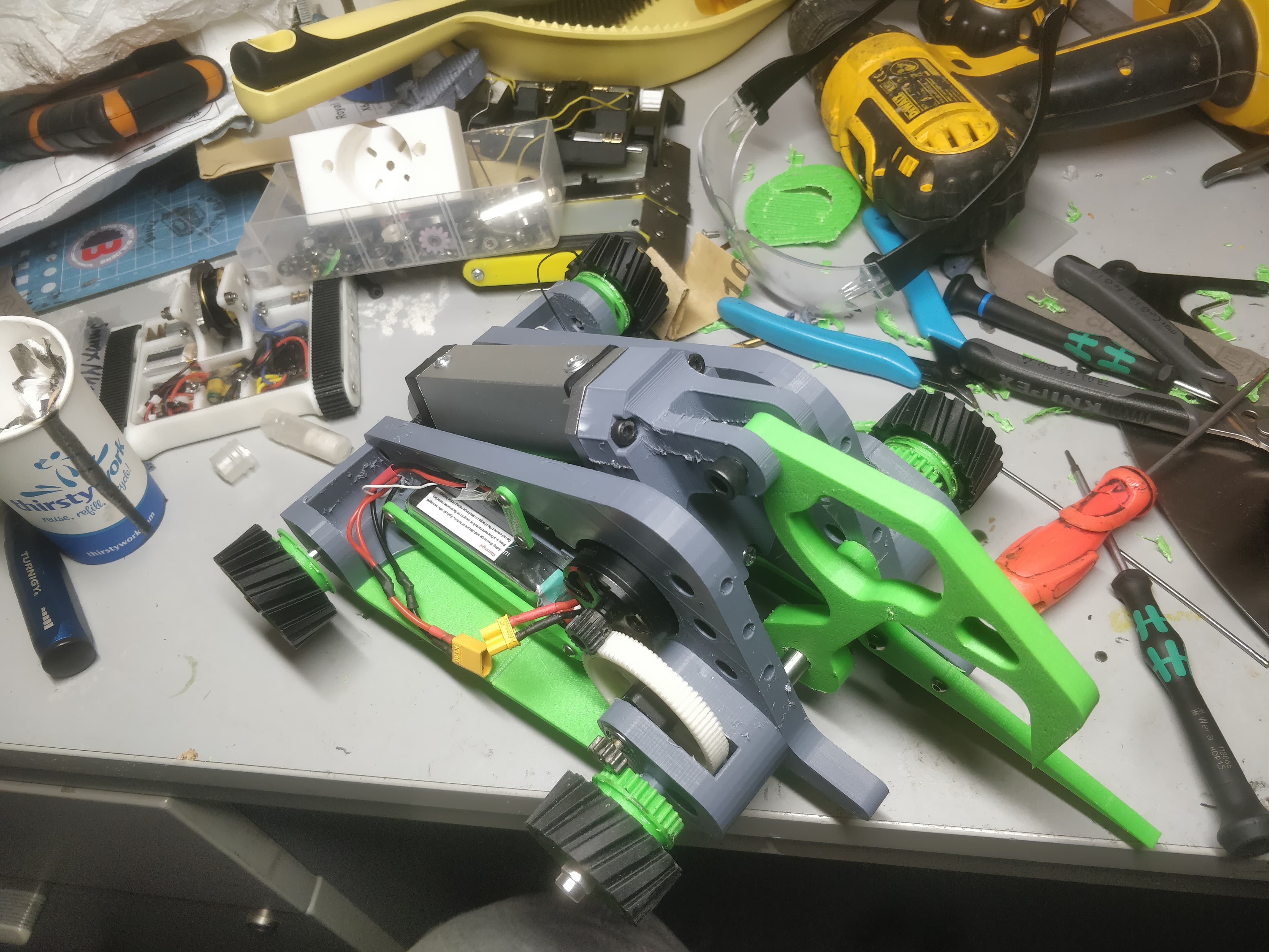
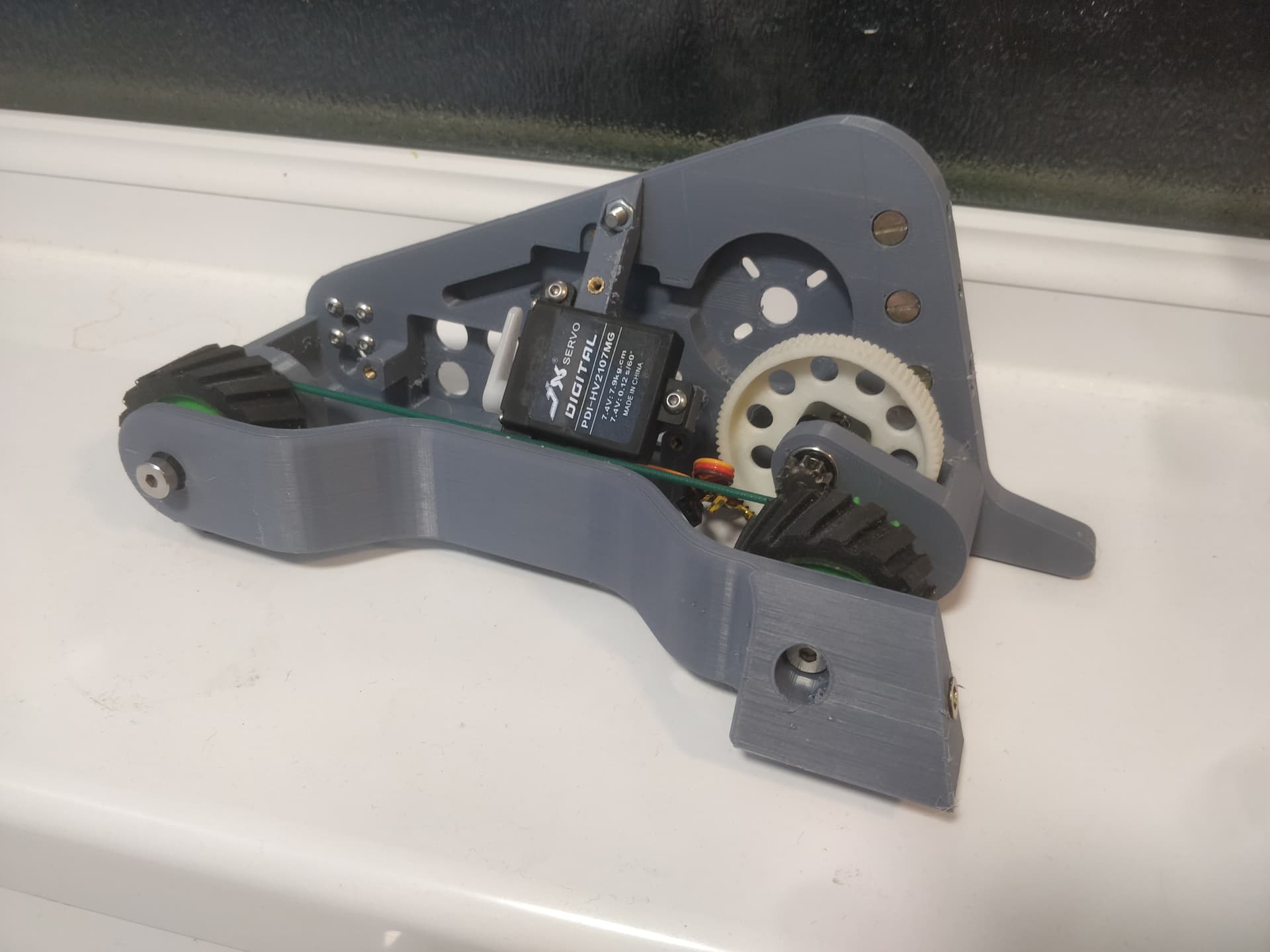
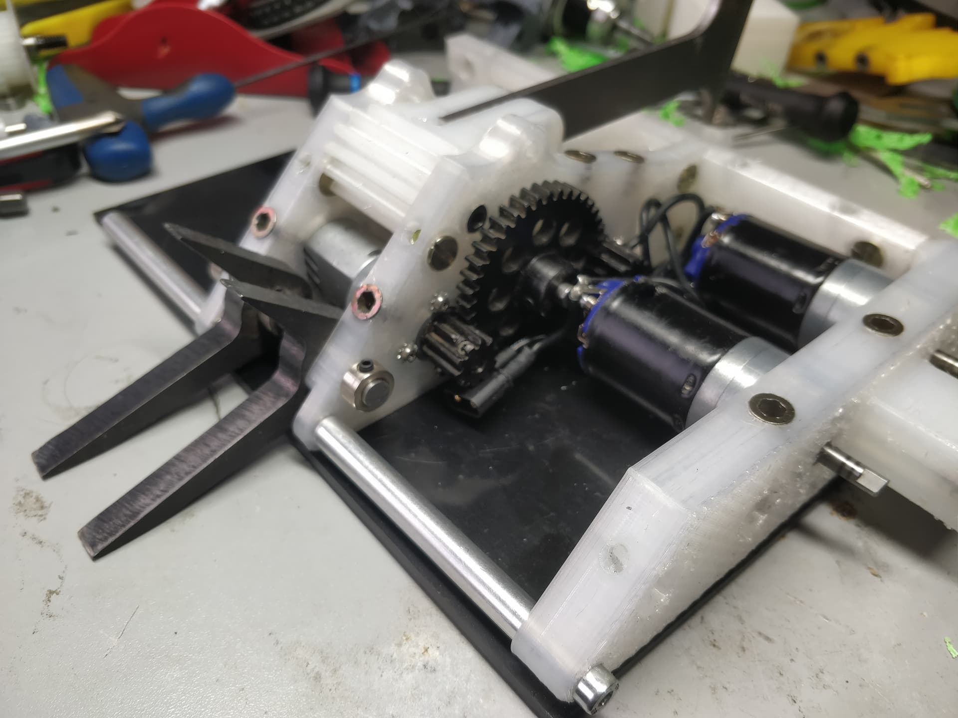
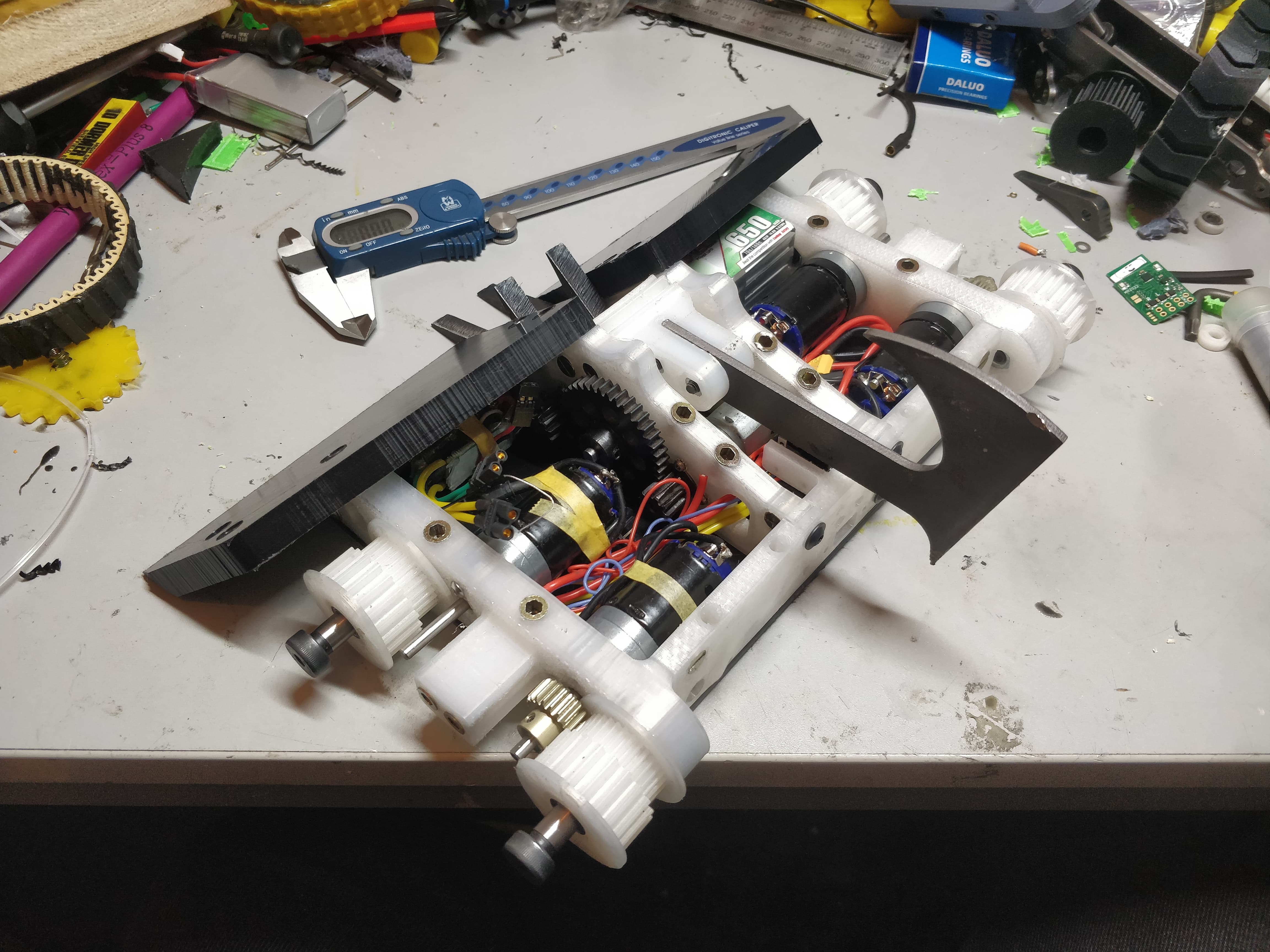
Still a bit of a parts bin special as I am going to try and use up as many parts as possible. This is reusing gears, bolts, bearings and batteries and BBB drive escs from MotherLoaders while also making use of those low kv 35mm outrunners and Klaus wheel moulds. The chassis as it stands is 3 parts, two printed bulkheads and a carbon fibre baseplate.

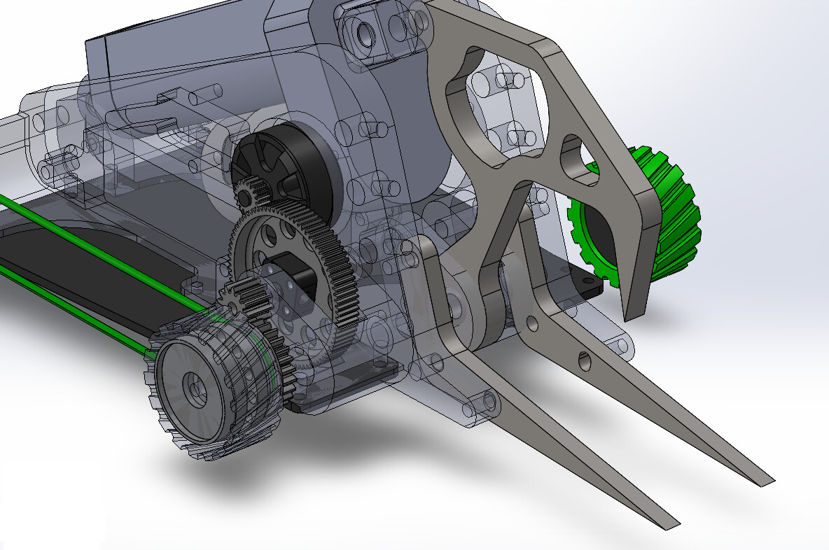
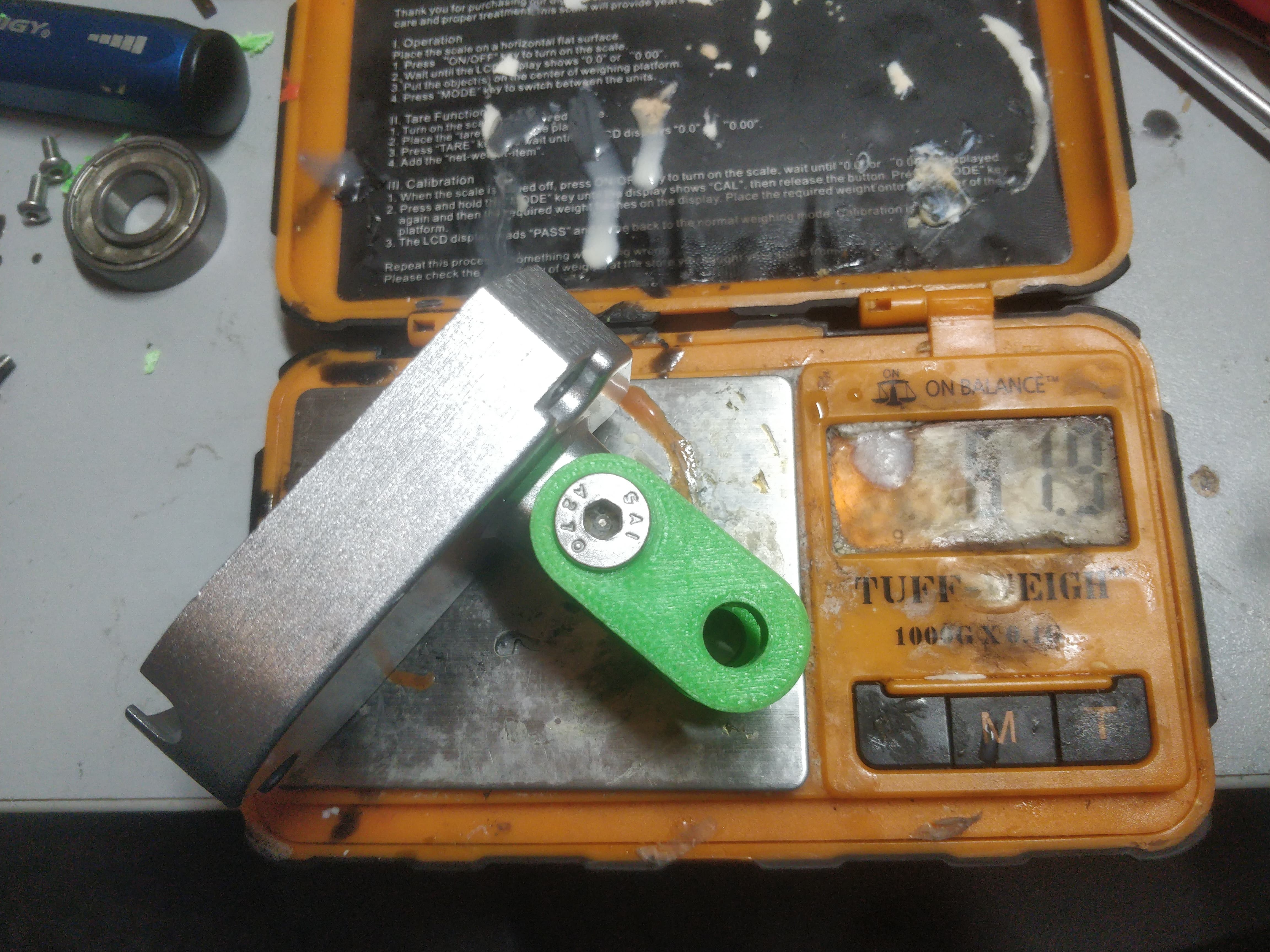
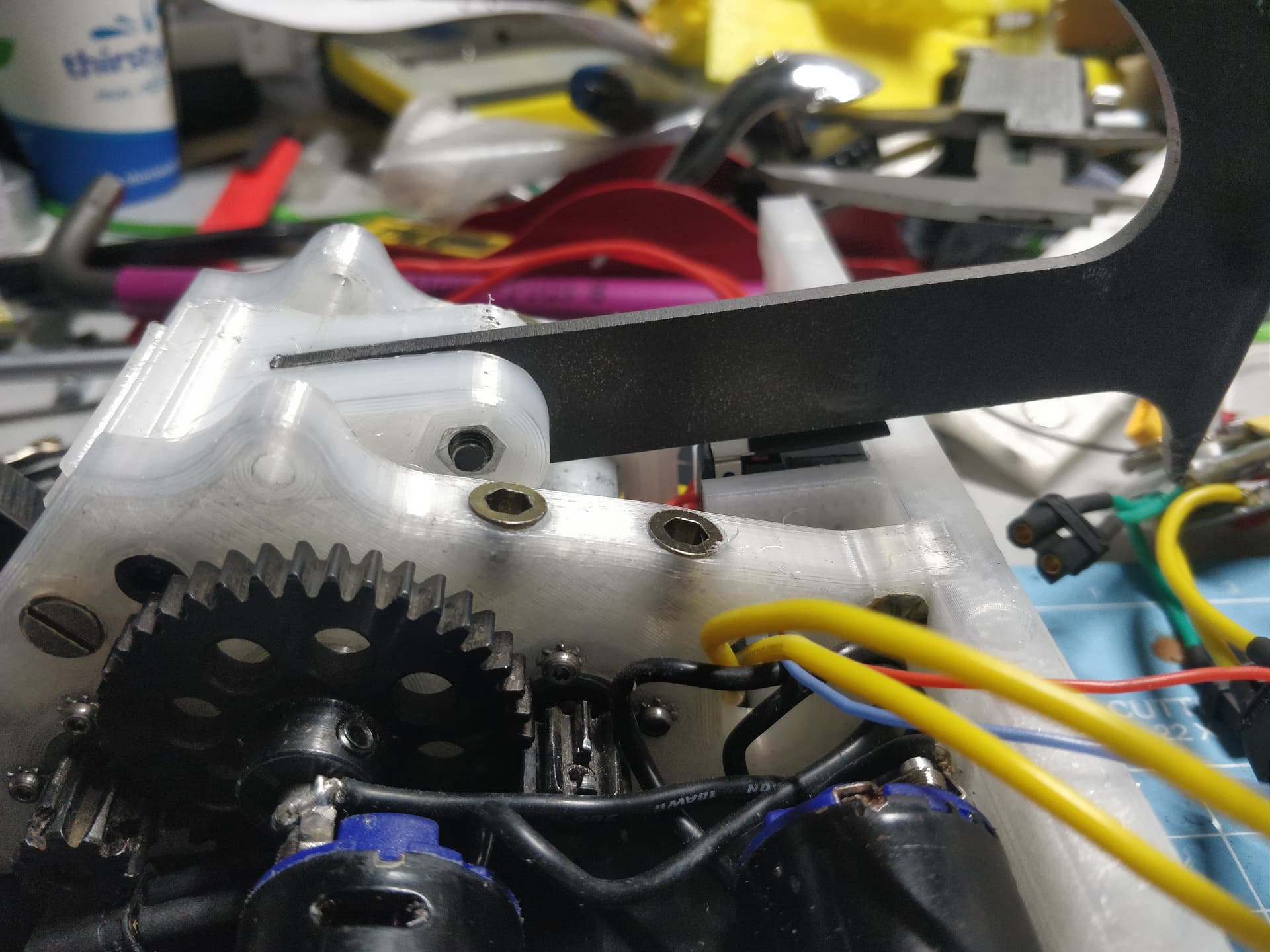
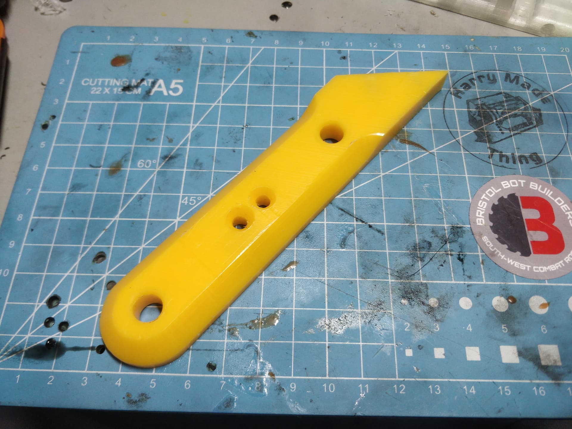
The main feature of this robot is obviously the crushing beak which is driven from a FW sized linear actuator. I junked the stock motor and replaced it with a 55 turn 540 motor which will be run off of 4s and will hate every moment of it. This and the beak as it stands are about 910g so I have about 500g with which to Draw The Rest Of The Owl. This is a monumental challenge but one I’m excited to take on.

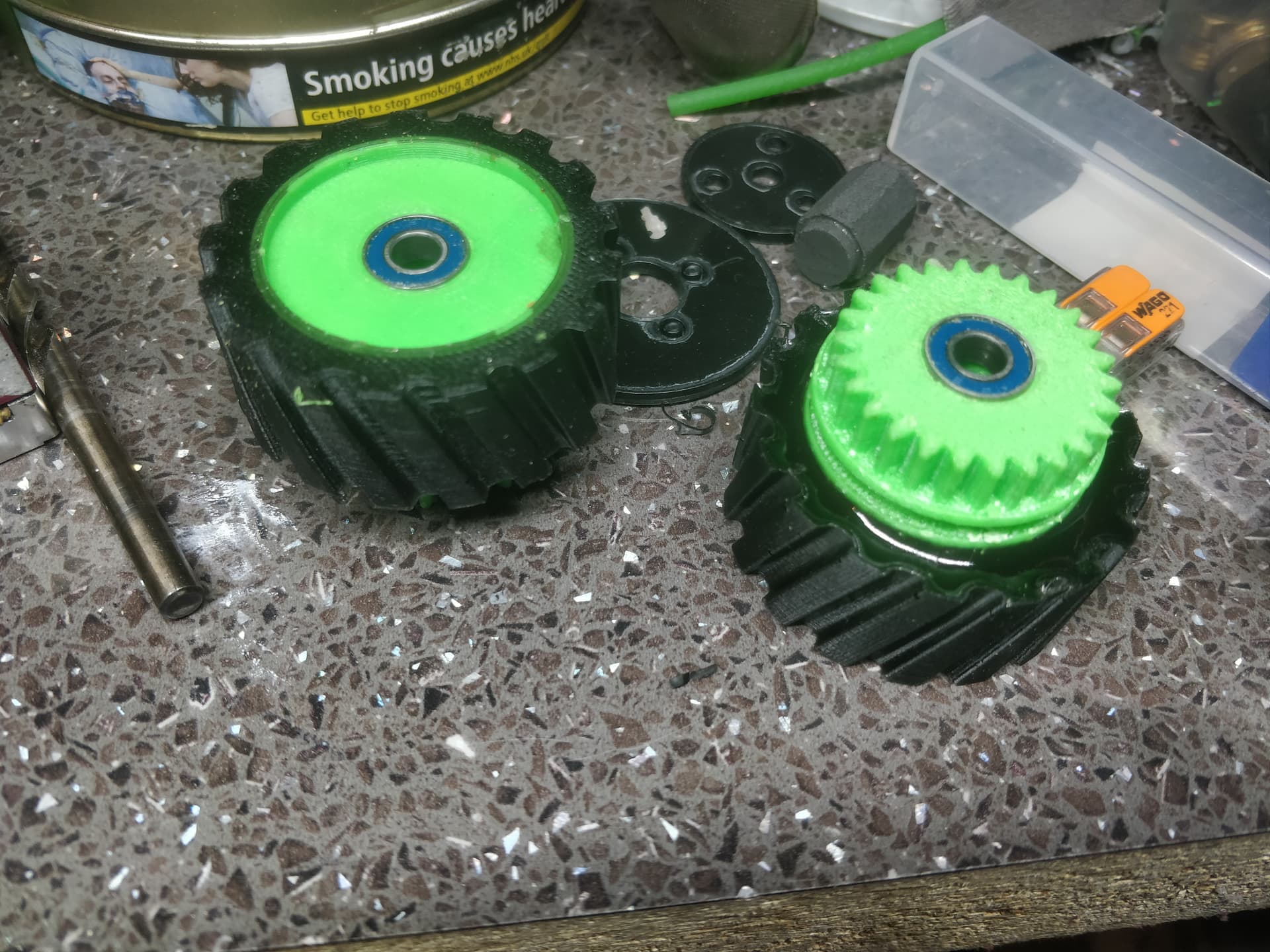
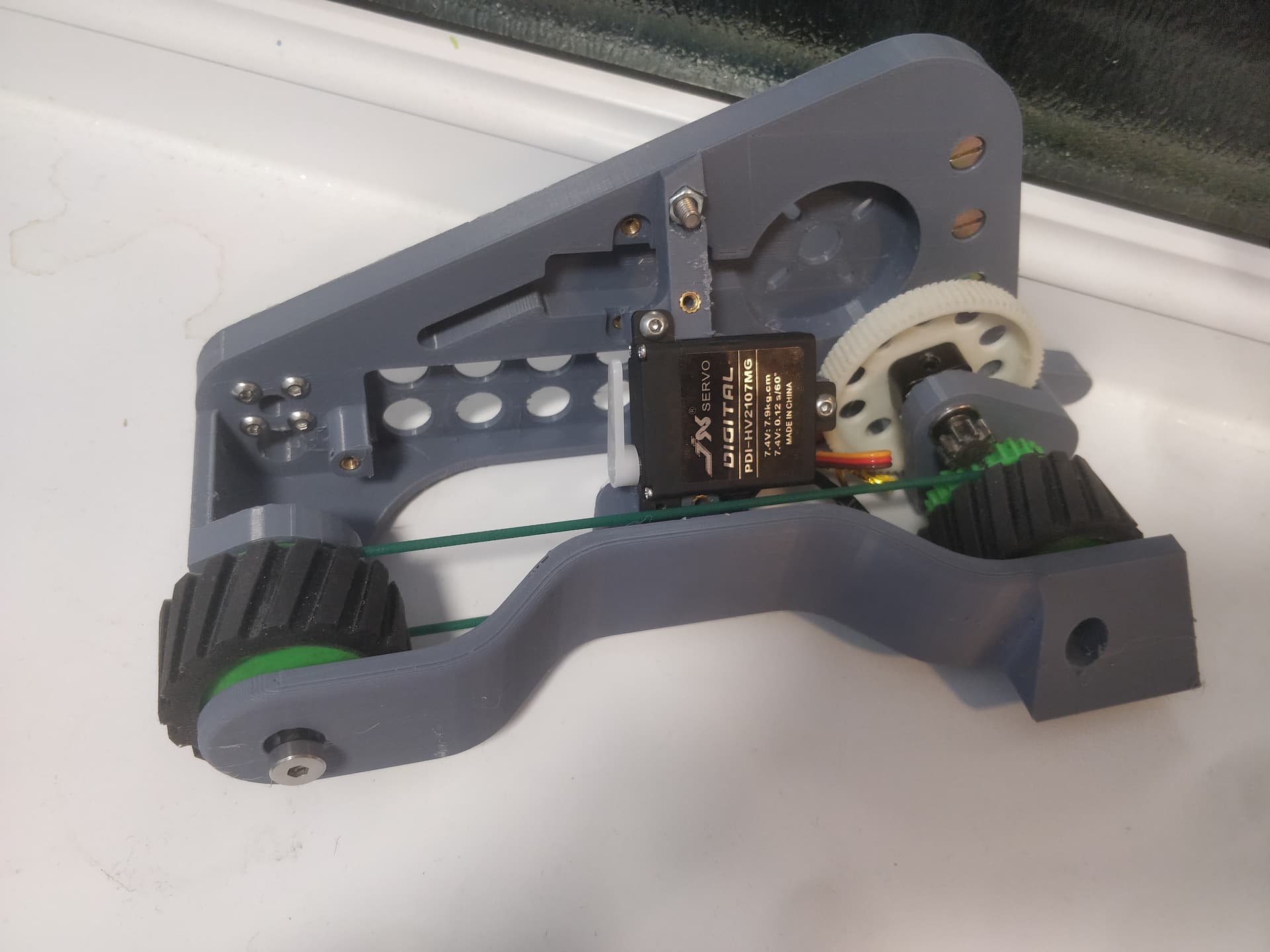
In order to make it simple and light I added some much needed complexity and weight. Yes. Instead of plugging in say, a 25mm and calling it done I have mushed in a structurally integral 2 stage spur nightmare. It’s a mixture of RC pinions and printed gears, tied together with a Mars hub from Ranglebox.

Planning to get this started alongside ML-T34’s improvement binge. I want to get it physical before jumping fully into it or abandoning it so ABS prototypes are on the horizon. Something of a palette cleanser maybe? If it goes badly I am just going to blame the Dutch.

6 Likes

so here for more crushers, this looks so fun.

That is looking awesome!

That is absurd and glorious and I adore it!

Will the forks be able to take the force, though?

Absurd and glorious is how I live my life so I’ll take that with a smile!

Honestly hadn’t put too much thought into it as my Gut-Feeling based FEA says it will be fine. The forks themselves run on a 5mm pin as a pivot point with two m4’s in slots top and bottom so it can wibble a few degrees up and down to hug the floor. I’d be more concerned about spinners bending or ripping them out than self inflicted damage.

There won’t be too much force at the tip of the claw, I’m not going to spit numbers until I can actually get a scale under there and squish it real good for actual data for stick waving. I can see it being a danger to anyone with a plastic lid with unsupported

What does look insanely dodgy is the spindly vulture neck where the ‘meat’ of the jaw has been removed to accommodate the absolute girth of the linear actuator - see above. While concerning it is still 8mm hardox which has a thinnest cross section of 10.2mm. Imagine a square bar 8*10mm and think how long a lever arm you’d need to budge that. Using that potentially treacherous logic I think I’ll be all right.

3 Likes

Now that the forks have some thickness to them they definitely look more reliable. I’d be scared of putting a set of scales in there though! My bathroom scales are rated up to 180kg, and while Antithesis probably doesn’t output that much force, I can’t calculate it well enough to say for sure. And you’re running a linac twice the size of mine!

Loving the look, getting a Pitch Black vibe, awesome :ok_hand:

1 Like

Awesome, so let’s get this right, you used a 540 brushed motor for the weapon, and brushless for drive. “Sick”, man :slight_smile:

Cheers John, Nice to see you on the forum too now!

@MarkR you got it! Brushless drive is those 35mm outrunners with a MOD0.6 stage that jumps up to MOD1 for the output stage. Overall it’s a 9.9:1 ratio to a 40mm wheel. Peppy on 4s but I hope to have some grunt so I can bully people before I can grab them as well as drag them around when they’re in the jaw. Actuator runs off a 55t 540 brushed motor - one I used to run in my old RC crawler. It seems pretty happy on 4s though I will need to play fast and loose hooking up the end stops!

I decided to prototype the chassis so I could see how it looks in the flesh

Quite proud of my little ender handling these fat flat parts like a champ. Just PLA there with the green being ABS but it works for a trial.

It’s fully wired there less a link and power light so I can start playing around as soon as transmission parts get ordered. I am super happy with the pivoting nature of the forks too. I hope the picture highlights how all that jazz interfaces.

To have a proper play I need to wait for the world at large to go back to work. I need MARS hubs, shoulder bolts, some 4mm silver steel, round polyurethane belting and some carbon fibre sheet. I can tweak a few things design wise and try and claw back grams here and there but a lot will be on hold to see if it’s going to drive like I want it to.

5 Likes

Looking awesome Harry - I’m absolutely here for it!

Drive gear train is cool, should have beans if the gears can take the strain and abuse - reckon it should too - breaking traction is a handy clutch for drive stuff anyway.

What’s the plan for self righting?

Looking great! Really enjoying the crusher renaissance we are having right now

1 Like

I imagine the gears will be okay too. I’m slightly hesitant about the first stage as its MOD 0.6 which is just on the lower end for my FDM abilities. The test gear works pretty well it just sounds a little rough as it is. I am putting that down to not having a proper bearing, shaft or hub to keep it concentric and straight. I’ll probably run the first stage in just so it’s super silky. The alternative would be to use a RC spur gear which I can get off the shelf in delrin give or take a tooth or two. They’re not super attractive from the off as they tend to be about half the width I need and would require a semi custom or hacky work around to slip in the space of printed gear & Mars hub.

Self righting is a bit of a fly in the ointment currently. I will have precious little weight left for trifling things like armour, let alone another mechanical system. I feel it will need to happen as it would be painful to get something like this not able to at least try and be present in a fight because it was instantly toppled. I want it to be a separate system, not built off the jaw mechanism so that it’s not crippled if that goes down. Something like the Witch Doctor ribcage would be amazing. I’m going to start looking at servos but light and torquey is going to come with a price tag. Strangbox waggly tail anyone?

1 Like

Imagine if you self righted via barrel roll - so rotating laterally you probably wouldn’t need a huge amount of torque and could probably get away with a relatively light weight servo? :thinking:

I love the look of this, and the bizarre irregularity of putting a FW linac into a Beetle. This robot may even require a sainthood since it caused a miraculous revelation re. the BBB ESC limit switches.

Regarding the beak, I don’t think the part you cut away to clear the actuator body is that much of an issue since it will always be loaded in pure tension (it’s pretty much aligned to the pivot). But there are some bits that are quite thinned down whose geometry is not aligned with the loadpath:


The blue and orange bits are in tension but they’re kinda curved so they’ll tend to distort under load and put all the load into the “inside” of the curve; the purple bit is in compression with some very thin parts that could distort/buckle.

I have made a linac with a drill motor before and it’s unlikely to be able to damage 8mm thick steel even there, but you could probably reduce the mass of the whole part by removing material elsewhere.

1 Like

Thanks for the analysis. I’m fairly confident in the shape like I said - at this scale I can still play fast and loose with good engineering practice.

Speaking of such I started a job where for the first time I’ll be an actual engineer driving a desk and I already miss making things with my hands so much I blasted out some beetle progress without so much as a single Teams Meeting.

I cast the Wheels reusing the Klaus geometry in 30a polyurethane. Hub is just ABS. These are the fronts and there is a lot going on, behind the geometry for the cast tyre is a pulley to drive the rear wheel and a MOD1 spur gear.

I took delivery of some of the new Ranglebox MARS hubs which were essential to the drive system. These solidly lock the gear to the 4mm shaft. At the moment I have uses for the 6mm variant locking the pins for the actuator too.

I had this idea out the blue while I was preemptively thinking how to cut weight wherever possible. This chunk of cast aluminum with the extended linkage weighs over 60 grams (if you couldn’t see past the crud on my scales)

I redrew this with a few token measurements that encompassed the extended pivot point as well. It is less than 20g in PLA so with nylon it’ll still be an incredible saving over the stock part and brings the total component count down.

I’m pretty sure this was about 700g stock so I’m pleased to see it where it lies now. The tolerance on the new cap needs tweaking to better interference but I imagine a 0.3-0.5mm expansion will do wonders.

This is where it currently lies - looking pretty robot shaped. I am really pretty close to something driving. Belting still needs to be ordered to get 4wd and realistically it needs bulkhead reprinting to do it properly but it’s going to be a race to see what wins out - my patience to wait for everything to be as intended or my adult ADHD robo-jubkie brain that wants to see it scoot along the kitchen floor.

Servos have been ordered for the self righting flicky bits so those will be integrated as soon as they arrive and I can get some real measurements and start playing with that aspect.

I keep going back and forth with the armour and how to produce it. I want flowing organic curves, I want cool shapes. I want it to be able to take hits. I want a girl with the right allocations, Who is fast, and thorough, and sharp as a tack… Sorry, Cake on the brain. But yes I have been considering moulding carbon fibre or trying an Ellis style sweepy swoopy printed TPU surround bumper.

Oh yes, BBB Beetle Brawl. Sadly MotherLoader didn’t make the cut again so he’s bench warming a reserve spot for now. The plan is to get it buttoned up and ready to go ASAP then return focus to this beastie. If I manage to luck my way into a full spot I’m running ML but if I’m only running whiteboards I’m 100% putting this up to bat instead. I know how ML works (or doesn’t!) So it’ll be nice to have a chance of pace.

6 Likes

The weight savings on the actuator are super impressive! I’m really looking forward to seeing it in action

Good evening sports fans.

MotherLoader-T34 has had the limit switch for the return added back in to it’s rear bulkhead and it’s all wired up ready to have a test fire when I get the baseplate cut.For the wedge I have decided to go with 10mm HDPE over UHMW this time, mostly for reasons of cost and the benefit not outweighing the effort and time waiting. Lots of little bits but it’s honestly no more than a hardcore weekend of work total.

Those who poke my Facebork mutterings will have seen this already but I have cracked how I wish to do the self righting flicky bits in Hard Nips.

So yeah that’s a huge mess of a CAD model but it showcases the idea. Basically two cheap and dirty slim wing servos that pop out a short arm that doubles as a bit of actuator armor when retracted.

I’m actually reasonably confident in what seems to be a small servo. Having used similar styles in the past they’re better then you’d think for the profile and the torque rating is in line with some standard size servos which I wouldn’t think twice about being man enough.

That’s the new bulkhead and armour prototyped. That’s only two parts still! While perhaps not the most sensible option, making my armour and my self righter mount the same part saves a lot of awkward joining of components at odd angles.

I think I will add another bracing point between the servo mount and the bulkhead but it should be close enough for a check. As of now I’m waiting on a manly BEC to run the servos on 7.4v and metal servo horns to test it out. Oh and I’ve run out of PLA! Shock horror!

3 Likes

Giving me Basilisk vibes in terms of looks and I mean that in a good way. Really nice so far.

Alright stunners. Gone done and made some robot parts didn’t I.

Going off the previous discussion about limit switches on the BBB esc I though I’d give it a crack for MotherLoader.

I got the motors bolted in and all the transmission components set up so I could test this. I printed a rear panel that has a micro switch mounting point and cut a chunk of 3mm HDPE to be a baseplate.

Here you can see it in the retract position. The switch has a little bit of foam heatshrunk (heatshrinkeded?) around the lever as a bit of compliance while I get a TPU bump stop finished.

Video on my facebork page and I’m thrilled with how well it works. Plus I’m equally jazzed about the grunt that dual Nerf motors give.

Next up I pulled my finger out and started making armour. I printed a template in ABS and set it up on my ghetto router table. I screwed the pattern to the part using the mounting holes which worked well.

Then I swapped in a 45 degree router bit to put the angle in. Much quicker than messing about with a hand plane.

Came out quite well to be fair. The front armour is 10mm HDPE which should be plenty for taking the abuse. I don’t intend to make spares

I made the other half in the same way, just taking care to reverse the chamfer. Get a look at the absolute width of this chap!

I am tidying up the wiring and casting a new set of tracks to get the proof of mobility deadline out the way, then it’ll all come apart to dye the chassis. Eagle eyed readers may have noticed the rear panel and one of the outer bulkheads are pretty rubbish. They’re SUPER damp but my normal tricks for drying nylon are falling short. It’s going in the bloody oven at this rate.

One more for the road! Currently printing templates for the side armour so those can be cut sometime this week too and I can get a realistic idea of final weight.

Cheers xoxo

6 Likes

Week until Brawl so I am entering the “lots, but none at all” stages of progress.

Most apparent is I cut out the 10mm yellow HDPE I am using for the sides. These are functionally identical to the old version but once the profile was cut I added a chamfer just for a bit of flair and to chuck out an extra couple grams.

I think they turned out really well for a handmade (technically) part. Just adds a little extra character to what could be just a rectangle with a 45 degree chunk out of it. It has two M4 screw inserts where it bolts too the wedge but otherwise is held with the shoulder bolts and two M4 countersunk bolts.

Also pulled my finger out and cast the new tracks. They’re 30a once again with a TPE core as it seemed to work well. I printed enough cores while I had the material loaded to have 3 pairs worth of spares. First time for everything! Now I can charge into spinners with even less fear.

Finally managed to get my nylon back to a good place and was able to sort out the last of the big prints. They had to stay together while I finished up the mechanics and such. Now that that is out of the way it’ll get stripped down and dyed a healthy glowing yellow. Once it is suitably jaundiced it will be time for final assembly.

Still needing a lid and such but it’s on the final stretch now. Weight is under control and the thing just works, really pretty well for a MotherLoader! Hopefully there are no disasters between now and then.

6 Likes